By C. G. McPROUD
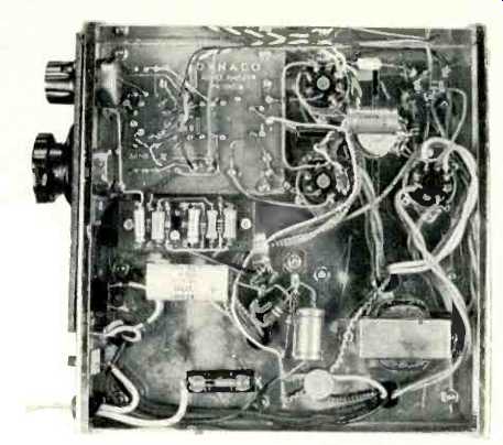
above: The completed Dynaco Mark III amplifier after conversion to
a 60-watt variable-frequency generator. The offset carrying handle
straddles the center of gravity.
THERE, ARE MANY TIMES when the hobbyist, recordist, or engineer wants a source of variable frequency.
He may want to change the pitch of a record or tape played on a machine which does not incorporate a vernier frequency control; 'he may be interested in experimenting with electronic music; or if he is an engineer, he may want to find out how a variation in supply frequency affects the performance of his equipment.
Falling in the latter category, the writer found that a variable-frequency source was necessary in testing equipment. One could, of course, start from scratch and build a professional, instrument, or possibly he could buy such a device ready made at a cost of a few hundred dollars. A quick study of the requirements shows that the desired 117 volts could be obtained from a conventional amplifier with a 500-ohm output. To have sufficient power to drive a turntable or most any tape recorder would require an output of, say, 60 watts. The output voltage across a 500-ohm secondary--the desired 117-would mean that the output power would have to be a minimum of 27.38 watts from the formula E^2/R=P.
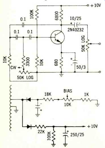
Fig. 1-Schematic of the oscillator section (upper) and the power-supply
changes (lower) for the variable-frequency generator.
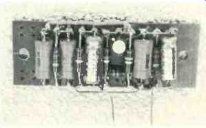
Fig. 2--The completed oscillator circuit assembled on a resistor-mounting
strip.
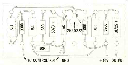
Fig. 3--Pictorial of the resistor-mounting strip assembled as a variable-frequency
oscillator.
The desired output impedance could be obtained by connecting a 500:8 line transformer backward across the output of a conventional amplifier, but that would mean that some form of generator would still have to be connected to the input.
The logical solution would be to take a 60-watt tube-type amplifier with a 500-ohm output and build into a simple variable-frequency generator.
There are many 500-ohm amplifiers available, but in general they are PA types and relatively expensive. The most reasonable solution was to obtain a Dynaco Mark III amplifier with a 500-ohm output transformer and build the generator into it.
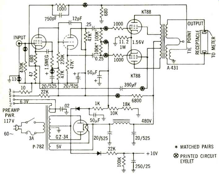
Fig. 4--Complete schematic of the original Mark III-500 amplifier, showing
changes made to provide the 10-volt supply for the oscillator.
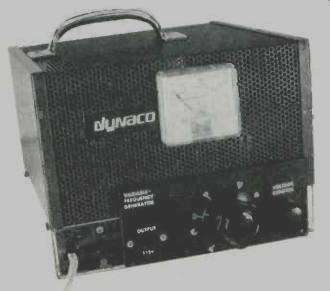
Fig. 5--Underside of the completed generator
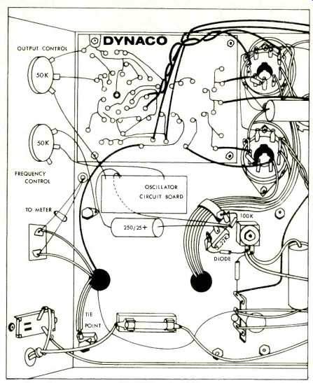
Fig. 6--Pictorial of the underside of the converted Dynaco Mark III.
The next problem was that of the type of generator to be used. The simplest choice seemed to be the phase-shift circuit, which can be made adjustable by substituting a variable resistor for one of the fixed resistors.
In general, the phase-shift oscillator employs three identical capacitors and three identical resistors to provide a single fixed frequency.
The Dynaco Mark III doesn't have adequate space for a vacuum-tube stage, so the oscillator would have to be transistorized. Since the amplifier employs a fixed-bias arrangement, there is a 60-volt tap on the secondary of the power transformer, together with a rectifier and filter network. We could have used a PNP transistor, but one wasn't at hand, while several NPN's were. Therefore, in the circuit of Fig. 1, the 40232 transistor was used. The maximum collector voltage for this transistor is 18 volts, and a tryout showed that the output was adequate and fairly constant over the desired range with a supply of 10 volts.
The addition of another silicon rectifier, two resistors, and a filter capacitor provided the required 10 volts from the tap on the transformer secondary.
Returning to the oscillator circuit, it was found that the circuit of Fig. 1 would give a range from 42 to 84 Hz with one turn of a 50k pot. The log taper pot-commonly called "audio taper," gives a reversed dial indication, but it spreads out the range in a desired manner. A 50-k reverse-taper pot would have changed this, but it was not considered sufficiently important to warrant the extra effort involved in getting such a pot. A second similar 50-k pot was used to control the output so the voltage could be varied to suit the required drain.
Construction
The oscillator circuit was assembled on a resistor-mounting board as shown in Figs. 2 and 3. These boards are available in several forms, and one of suitable size was procured. It was too long for the circuit, so it was shortened by simply cutting off the overage.
Space was left for two holes for mounting, using #6 x 3/4 sheet-metal screws through holes drilled in the chassis in the location shown in Fig. 4, and using 1/2-in. bushings to hold the strip away from the chassis.
The octal socket on the front apron of the amplifier was removed, as were the output terminal strip and the input phono jack. In place of the latter was put the 50-k output pot, using a 3 x 5 Bakelite panel on the outside of the apron. The frequency-control pot was mounted on the Bakelite panel in the approximate position of the former octal socket, and an receptacle was mounted in the position of the output terminal strip. The Bakelite panel provides space for the decal lettering, as well as to cover up the holes in the chassis.
As a final gesture toward a finished appearance, a hole was cut in the cover to accommodate a 150-volt a.c. meter so the output could be adjusted as required and without exceeding the input voltage for the equipment under test. Actually, 60 watts of power would provide an output of 173 volts, which underlines the need for an output voltmeter.
The supply for the oscillator is built directly on the Dynaco chassis. A 1-amp, 400 P/V silicon diode is connected to the selenium bias rectifier at the point where the lead from the transformer is connected. Its other end is connected to a tie point mounted on the same screw that holds the present one, and the 22k (1-watt) and 100-k (1/2 watt) resistors are mounted on the new tie point. At their junction, connect the + end of the 250-AF, 25-V filter capacitor, and connect the end to a soldering lug mounted under one of the transformer-holding screws. The leads from the input phono jack are unsoldered from the existing circuit
board and replaced by a pair of leads from the output potentiometer. A 3/8 in. hole in the top of the chassis near the output receptacle if fitted with a rubber grommet, and leads to the voltmeter are passed through it. Since the whole assembly weighs around 29 lbs., a carrying handle was thought necessary. Its position is shown in the photo of the finished device. It may seem strange that it should be so off center in appearance. It is, however, straddling the center of gravity, so the unit carries level with the handle in the position shown.
The labeling on the Bakelite panel was done with decals. The positioning of the frequency-designating figures was determined by comparing the output on a 'scope against that from a conventional audio oscillator. It could be done by Lissajous figures against the line frequency, if no oscillator is available.
The generator has a fairly constant output with a given load, so it is possible to set the output voltage once and then vary the frequency over the entire range without changing the output control. For those requirements of variable voltage, the frequency may be set and the output varied from zero to over 150 volts with the usual turntable or tape recorder.
Changing the 0.1-uF capacitors in the oscillator circuit should move the covered frequency range from the 40 to 80-Hz range to anywhere desired.
For a range of 60 to 120 Hz, a capacitor value of .068 should be about right, although some trimming might be necessary. The 3300-ohm resistor limits the high-frequency end of the range, and the total range is determined by the value of the frequency control pot. A value of 50k ohms is about the maximum that will permit the oscillator to function. If the 3300 ohm resistor is decreased appreciably, it effectively shorts out the phase shifting network and oscillation will stop. The values shown in the schematic were chosen for the desired range and reliable operation.
While any power amplifier will function in the same fashion as this one if the output transformer is changed to provide the 500-ohm output, it would likely require some experimentation to achieve the desired result. The Dynaco Mark III is priced in kit form at $89.95, and the remainder of the parts should not exceed another $15.00 at most. So for around $105.00 can have a variable frequency generator for whatever need you may have for one. If you already have a Mark II or Mark III that is retired from hi-fi service, you can replace the output transformer with a 430-500 for only $44.95 and start using the amplifier again. In any case, you are sure to find the variable frequency generator a useful tool in the shop, and a great help if you dabble in electronic music.
Parts List
1 10-µF, 25-V electrolytic, Sprague TE 1204
1 250-µF, 25-V electrolytic, Sprague TVA 1208
1 50-µF, 3-V electrolytic, Sprague TE-1302
3 0.1-µF, 10% capacitor, Sprague 192P10492
1 680-ohm, 1/2-watt, 10% resistor
1 3300-ohm, 1/2-watt, 10% resistor
1 6800-ohm, 1/2-watt, 10% resistor
2 10k, 1/2-watt, 10% resistor
2 100k, 1/2-watt, 10% resistor 1 22k, 1-watt, 10% resistor
2 50k audio taper pots, IRC 13-123
1 40232 transistor
1 3 x 5" Bakelite panel, 1/8" thick 1 a.c. panel-mount receptacle
1 2" knob
1 1 1/2" knob 1 150-V a.c. voltmeter
1 resistor mounting strip
1 two-lug terminal strip (tie point)
Decals
Handle
Miscellaneous hardware, wire, solder, etc.
==========
(adapted from Audio magazine, Jan. 1970)
Also see:
= = = =