MANUFACTURER'S SPECIFICATIONS:
TUNER SECTION: FM: IHF Sensitivity: 1.8 µV. S/N: Better than 60 dB. THD: Less than 0.8%. Selectivity: Better than 40 dB. IHF Capture Ratio: 1 dB. Image Rejection: Better than 90 dB. I.f. Rejection: Better than 95 dB. Spurious Response Rejection: Better than 90 dB. Stereo FM Separation: Better than 35 dB @ 1 kHz.
AM: Sensitivity: 100 µV/meter. Image Rejection: Better than 50 dB. I.f. Rejection: Better than 80 dB. Selectivity: Better than 20 dB.
AMPLIFIER SECTION: IHF Music Power: 120 watts @ 4 ohms, 90 watts @ 8 ohms. RMS Power: 43 watts/channel @ 4 ohms; 35 watts/channel @ 8 ohms. THD: Less than 0.8% at rated output. IM Distortion: Less thin 0.8% at rated output. IHF Power Bandwidth: 20 to 40,000 Hz at 8 ohms. Frequency Response: Power amplifier: 10 to 50,000 Hz ± 1 dB; Overall, including preamplifier-control section: 20 to 40,000 Hz ± 1 dB. IHF Hum and Noise: Phono 1 & 2: Better than 70 dB; Aux: Better than 75 dB. Input Sensitivity: Phono 1 & 2: 2.5 mV; AUX: 150 mV; Tape Monitor: 150 mV. Damping Factor: 24 @ 8 ohms. Speaker Impedance: 4 to 16 ohms. Tone Control Range: Bass: ± 12 dB @ 50 Hz; Treble: ± 12 dB @ 10,000 Hz.
GENERAL: Dimensions: 17-7/16" w. x 4-15/16" h. x 13-3/16" d. Weight: 27.3 lbs.
Suggested retail price: $299.95.
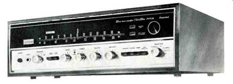
It was with a great deal of pleasure and satisfaction that this department examined the Sansui Model 2000A. Pleasure, because this unit is one which meets its performance specifications and then some, and satisfaction because we looked back at some of the suggestions we had made when we reviewed its predecessor (Sansui Model 2000, reviewed in AUDIO, Oct. '68, p. 70) and found that just about all our earlier suggestions had been acted upon. The 2000A, however, is more than just a dressed up Model 2000. It is a totally new and updated design, from front panel to rear, and the circuitry has been updated to state-of-the-art technology as well.
The lower portion of the gold and black front panel includes a power push-push switch, phone jack, separate but concentrically-mounted individual-channel bass and treble controls, master volume control, balance control, and signal-source selector switch. Secondary pushbutton controls at the left include low- and high-frequency filters, while a bank of four such buttons at the right perform the functions of loudness-contour, stereo normal/reverse, mono/stereo selection, and tape monitor. These buttons, too, are of the push-to-make, push to-break type. The upper portion of the panel is effectively "blacked out" until power is applied. With the selector switch in either the AM or FM position, an expanded dial scale becomes illuminated, as does a peak-reading tuning meter to the left of the dial scale. The meter is usable in both AM and FM service. Noteworthy is the linear FM dial scale which has practically become a trademark in Sansui products. Spacing between every "MHz" on the dial is equal, making the accurate tuning and reading of signal frequencies a simple and repeatable process. In any of the other selector-switch positions, the calibration and meter illumination "black out" and a single illuminated identification, such as PHONO 1 or AUX, appears along the upper edge of the blacked out area. To the right of the dial-scale area are two more push-push controls-one for defeating the FM interstation-muting circuits and one for introducing an MPX (Stereo FM) noise-cancelling circuit, useful when listening to distant stations transmitting stereo programming received somewhat noisily because of weak signals. At the extreme right of the panel is the tuning knob, coupled to a very effective flywheel that permits spanning the entire dial with one good twist of the knob-and with such an expanded dial scale, that's quite a feat. The dial pointer, by the way, is softly illuminated in red, making it visible from across a room for remote identification of frequencies.
Significant improvements over the earlier Model 2000 are in evidence on the rear panel as well. In the cluster of eight input and output jacks at the right, two phono pairs are now provided (there used to be a single pair for phono and a pair for seldom-used "tape heads"). A heavy grounding terminal is also located in this area. Just below the DIN (European) tape recorder jack, there are now a pair of jumper bars which connect from the preamplifier section to the power amplifier section of each channel. Removal of these jumpers enables the user to install any of the many accessory items, such as reverb units, custom multiple-tone controllers and, conceivably, even "a four-channel stereo decoder," should such an item become the mainstay of conversion to quadraphonic sound. This new convenience is in an area of the rear panel formerly occupied by a user-adjustable stereo FM separation control which we pointed out in the earlier review shouldn't be user controlled at all! Increasingly popular "piano key" speaker terminals (the type which require only pushing down and inserting the stripped speaker lead ends) have replaced conventional barrier terminal strips of the earlier model, and there are provisions' for two full pairs of stereo speaker systems.
These terminals flank a pair of quick-acting speaker fuses. In the event of failure of these fuses for any reason, a "Protector" light on the front panel becomes illuminated, directing the user to the source of the trouble. As you pivot the AM bar antenna downward, a local/distance switch is disclosed, as well as a rotary control for setting desired FM interstation mute thresh hold. A pair of convenience AC outlets (one switched, one un switched), the main line fuse, and FM and AM antenna terminals (also of the "piano key-depress" variety) complete the back panel layout. There are separate pairs of terminals for both 75-ohm and 300-ohm transmission line connection and a second grounding terminal at this end of the back panel.
Circuit Description
Removal of the metal housing and bottom cover of the Sansui 2000A disclosed a well-organized layout of ten modular p.c. boards plus a fully-sealed (except for the AM variable capacitor gangs) front-end section (see Fig. 1). The RF stage of the FM front-end is an FET, while the remaining three devices in this section are bi-polar transistors. The i.f. amplifiers (FM) use four IC devices, each of which contains the equivalent of five transistors. In addition, this section contains a three-transistor plus-three-diode mute circuit so designed as to afford virtually "no transition" distortion at signal strengths near the mute threshold setting. A completely separate AM section is used, consisting of four more transistors and three diodes and utilizing no parts in common with the FM i.f. section. In. all, the active device complement of this new receiver consists of 45 bi-polar devices, 1 FET, 4 IC's, 28 diodes and 2 Zener control diodes.
Both high-level and low-level signals are fed through the preamplifier audio stages. While normally we prefer to see the high level inputs by-pass the preamp stages (for better S/N and hum), we must admit that in this instance, high-level input hum was quite acceptable, measuring in excess of the 75 dB claimed. Quality of components used throughout the receiver seemed excellent, with over-rated parts used particularly in capacitors and power transformer, which was cool after nearly four hours of high-power testing. The output coupling capacitors in this "single ended push-pull" amplifier circuit are 2200 nF, 75 volt units, for example. The total supply voltage is 65 volts and only half of that voltage (approximately 32.5 volts) appears across the output capacitor, since it is at the mid-point of the two series-connected transistors. Still, a 75-volt electrolytic capacitor is used so that in the unlikely event of a total short of the upper transistor (TR-6), the full voltage then appearing across C-1 would still not be sufficient to damage the output capacitor. The reactance of a 2200 uF capacitor at 20 Hz is a little under 4 ohms, by the way, and at 100 Hz it is less than 0.75 ohms. Thus above 100 Hz, the damping factor of the amplifier is just about independent of the output coupling capacitor. The power amplifier section of one channel is shown, schematically, in Fig. 2.
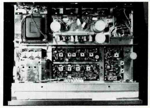
Fig. 1--Showing top view.
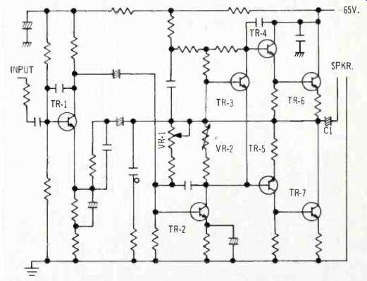
Fig. 2--Schematic of one power amplifier channel. Output capacitor C1 is
2200 uF, VR1 and VR2 are bias adjustment controls.
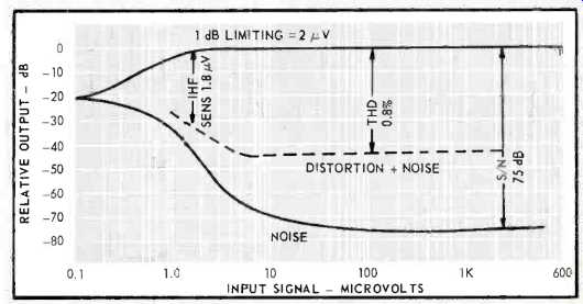
Fig. 3--FM characteristics.
FM performance characteristics of the Sansui Model 2000A are depicted graphically in Fig. 3, and it is interesting to note how the new design has resulted in significant improvements in almost every FM specification concerned, compared with the earlier Model 2000. For example, the old measured sensitivity was 2.2 µV as opposed to the present 1.8 µV. We are happy to see that the published specifications dropped the old "± 3 dB" which had been associated with this measurement. Full limiting is at 2 (it used to be at 3 µV), and the signal-to-noise ratio is now a very fine 75 dB, whereas the best figure obtainable from the older model was 67 dB. THD, however, remained about the same, at around 0.8%, as claimed.
Detailed measurements of the amplifier portion of the Sansui 2000A disclosed that it, too, has undergone significant improvement compared with the older Model 2000. We measured 38 watts rms per channel at rated distortion of 0.8% this time and were able to produce 40.5 watts before reaching a THD of 1.0%. This is about 5 watts better than the older model (10 watts, if you add up both channels, since both channels were driven during all THD and IM tests). IM was about 0.6% at rated power (35 watts) and 0.7% at 38 watts, considerably better than the 0.8% claimed by the manufacturer for only 35 watts. At very low power levels, however, there is a slight tendency for both the THD and the IM to increase slightly, a not unfamiliar characteristic of a great many solid-state products. The THD seemed more prone to this effect than the IM, reaching a maximum of about 0.5% at very low listening levels of 100 milliwatts or so. Part of the increase may be attributable to residual hum and noise influence on the distortion meter, but part of it was definitely perceived on the oscilloscope as an increase in THD at these very low levels. Since the maximum never exceeded 0.5%, however, it is unlikely that you would be able to hear this effect under normal listening conditions. Plots of both THD and IM are shown in Fig. 5. Figure 6 confirms the power bandwidth claims of the manufacturer, extending from 20 Hz to 40,000 Hz for the half-power points. Roll off below the 20 Hz point is probably deliberate, in keeping with the design philosophy of many manufacturers who feel that there is no point in producing large amounts of power (usually because of rumble of turntables or other low frequency effects) at frequencies which cannot be heard in any event. Tone control response, shown in Fig. 7, seems to have remained about the same as in the earlier model and is quite adequate in actual use. High frequency filter action is excellent, beginning as it does at 4 kHz and having a 12 dB-per-octave slope. We felt, however, that the low frequency filter still cuts into the program material a bit too obviously, with 10 dB of attenuation at 50 Hz. These characteristics, as well as loudness-contour action at a-30 dB setting of the volume control are also plotted in Fig. 7.
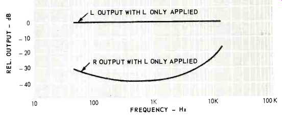
Fig. 4--Stereo separation.
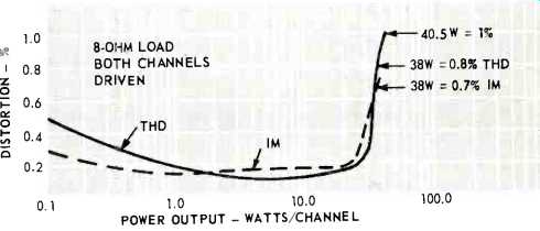
Fig. 5--THD and IM distortion.
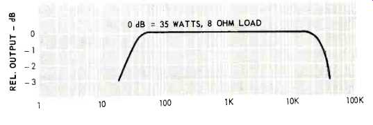
Fig.6--Power bandwidth.
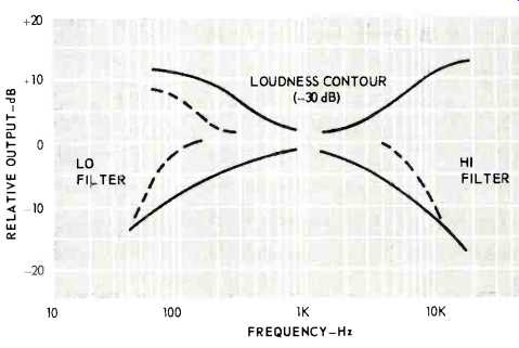
Fig.7--Tone control, filter, and loudness characteristics.
Listening Test
There are some features of the Sansui Model 2000A which haven't changed a bit, compared to the earlier design. In listening to this receiver, we were once again struck by the excellence of the muting action of this (and just about every other) Sansui product in the receiver category. We set up the mute threshold adjustment for about 8 microvolts and were able to pick up 48 noise-free stations with the aid of a directional high-gain outdoor antenna some 17 miles from New York City. Defeating the mute completely raised the number to 53, of which all but about two were still noise-free (or at least sufficiently noise free to make the program listenable). This means that at least four more stations having input-signal strengths of less than 8 microvolts were producing satisfactory quieting (of the order of 45 to 50 dB) which corresponds very nicely with our earlier laboratory measurements. It is difficult to appreciate the nicety of a linear FM dial scale until you've used one. We were able to move from channel to channel by moving the dial pointer exactly one notch on the 0-100 logging scale regardless of whether we were dealing with the low end or the high end of the band. Calibration, by the way, was excellent, as it should be with such an expanded scale. Automatic stereo switching was positive with no erratic stereo light indications in the presence of interstation noise. A word is in order concerning the MPX NOISE CANCELLER button on the front panel. It works-with very little reduction in overall separation (even at the high end). We tried it while listening to a stereo station some 60 miles away (which, admittedly, was noisy in stereo) and found that by depressing the MPX NOISE CANCELLER (it deserves a much better title, by the way) we were able to get rid of a good deal of the background hiss normally associated with fringe stereo FM listening. Don't expect it to help your multipath problems, however. Nothing can do that except a properly oriented and selected FM antenna! In using the phono inputs, we found that inputs 1 and 2 have the same sensitivity and yet, the results obtained in PHONO 2 seemed to have a more peaked response than PHONO 1 input.
Only then did we discover that the PHONO 2 input has a 100-K load resistance-too high for our (and most everyone else's) cartridge. Once you know this, it is easy enough to add another 100K resistor externally, reducing the load resistance across the PHONO 2 input to the more usual 50K or so. We know of no cartridge that requires a load of 100K for flat test response and would rather see two different sensitivities for the two phono inputs-a much more useful and less confusing feature.
In any case, hum and noise on both phono inputs as well as in the Aux position were remarkably low-in no way detracting from any of our listening experiments' success.
Lest the good people at Sansui become complacent and assume that they have reached perfection (a dangerous assumption for any maker of high fidelity component products), we must end with a minor criticism. The "local-distance" switch, hidden behind the AM bar antenna is really an anachronism in view of the overload-proof FET front end. Should it be inadvertently switched to the "local" position, a user unaware of its presence might well rush the set back to the dealer for servicing, thinking that the receiver is insensitive and defective.
Please do away with this switch--it just isn't needed any longer! It goes without saying that if the old Model 2000 at $299.95 was excellent value in 1968, the new 2000A, at no increase in price, is doubly so and only further confirms what our industry has maintained for years in the face of rising prices in other manufacturing fields--you get more for your high-fidelity component dollar today than ever before. The Sansui 2000A is one of the sets that proves it!
-L.F.
(Audio magazine, Jan. 1971)
Also see:
Sansui Model BA-5000 Stereo Power Amplifier (Equip. Profile, Nov. 1977)
Sansui AU-D11 Integrated Amplifier (Feb. 1982)
Sansui Model SR-838 Direct-Drive Turntable (Feb. 1979)
Sansui PC-X1 PCM Digital Processor (Jan. 1984)
= = = =