MANUFACTURER'S SPECIFICATIONS
Tuner Section:
IHF Sensitivity: 1.7µV. Quieting Slope: 55 dB at 5µV; 60 dB @ 10 µV. S/N: 75 dB.
Capture Ratio: 1.0 dB.
THD: Mono, 0.15% Ca 400 Hz, 0.3% from 50 Hz to 10 kHz; Stereo, 0.3°4 C, 400 Hz; 1.0% from 50 Hz to 10 kHz.
Selectivity: 80 dB.
Image Rejection: 110 dB.
I.F. Rejection: 110 dB.
Spurious Response Rejection: 110 dB.
AM Suppression: 55 dB.
Stereo FM Separation: 45 dB C 400 Hz; 35 dB from 50 Hz to 10 kHz.
Frequency Response: 20 Hz to 15 kHz + 1.5 dB.
Sub-carrier Suppression: 60 dB.
Muting Override Level: 10µV to 30 µV, variable.
Amplifier Section:
Power Output: 70 watts per channel, 8 ohm loads, both channels driven, at any frequency from 20 Hz to 20 kHz. X 95 watts per channel, both channels driven, 4 ohm loads, at any frequency from 20 Hz to 20 kHz.
Rated Harmonic Distortion: 0.1% at rated power.
IM Distortion: 0.1% at rated power output. Damping Factor: 70 @ 1 kHz.
Frequency Response: Phono, RIAA ±0.2 dB; AUX & Tape, 10 to 50,000 Hz, +0.5 dB,-1.0 dB. Input Sensitivity: Phono, 3 mV; AUX, 150 mV; Mic, 3 mV.
Hum and Noise (IHF "A" weighting net work): Phono, 80 dB; Mic, 70 dB; AUX and Tape, 90 dB; Residual (volume at minimum), 100 dB.
Tone Control Range: Bass, ± 15 dB @ 50 Hz; Treble, +10 dB @ 10 kHz.
Low Filter:-3 dB at 20 Hz or 70 Hz.
High Filter:-3 dB at 6 kHz or 12 kHz.
General Specifications:
Maximum Power Consumption: 430 watts.
Dimensions: 20 in. W x 13 1/4 in. D x 6 3/4 in. H.
Weight: 42 lbs.
Retail Price: $850.00.

Fig. 1--Rear panel of the Yamaha CR-1000.
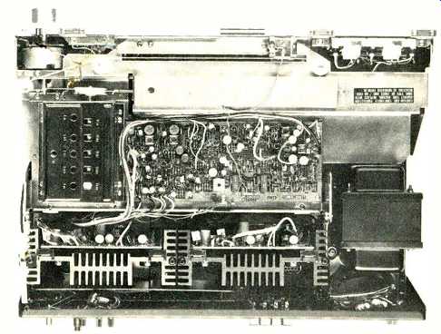
Fig. 2--Internal view of the chassis.
Yamaha's top stereo receiver is one of the most expensive on the market and is one of a handful of receivers which lack AM circuitry. Both of these facts immediately suggest that the performance of this receiver is to be compared with the performance obtained with separate components.
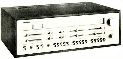
The unit differs in appearance from most stereo receivers in that there are only two rotary knobs on the entire front panel-one for tuning, the other serving as a master volume control. All other control functions and switching operations are performed by means of slide controls, slide switches, and piano-key toggle switches, which occupy the lower two-thirds of the panel height. The dial-scale area is rather narrow, though well illuminated and calibrated with a 0-100 logging scale in addition to the usual MHz markings. At the left are signal-strength and center-of channel meters, while the right-hand end of the dial area has three indicator lights: one for power, one to signal stereo reception, and one which Yamaha calls an "AFC/Station Indicator." This last light works in conjunction with a capacitance effect when touching the tuning knob. So long as your fingers touch that knob, the built-in AFC circuitry is defeated while you tune accurately to the FM station of your choice. When the knob is released, and assuming a station has been tuned, the panel light turns on, indicating the AFC circuit is correcting possible mistuning. This refinement requires a preamplifier, three transistors, a couple of signal diodes, and the indicating LED light, not to mention the passive capacitors and resistors required in the associated circuits.
Horizontally oriented slide controls vary muting thresh old, microphone input volume, bass, treble, left-right balance, and loudness. The loudness compensation arrangement is one of the few found on modern receivers that actually' permits the user to employ loudness compensation meaningfully. With the loudness slide lever set to the right, indicating "flat," the user adjusts the volume control to the loudest desired level. Then, increased settings of the loudness slide lever introduce just the right amount of loudness compensation. This dual control system is more effective and accurate than the arbitrarily designed combination volume/loudness control found on most competitive receivers.
Three position high- and low-filter slide switches provide two cut-off points plus an "off" position for each filter. Similar slide switches are used to set the turnover points for the bass and treble controls, with a flat position available for tone-control defeat. Eighteen toggle switches located along the bottom of the panel take care of power on/off switching, speaker system selection (one or two possible pairs or both), mono and stereo modes (including left-only, right-only, and left-plus-right mono, stereo, and stereo reverse).
Five of these switches are program source selectors (there is provision for two phono input pairs, two AUX pairs and, of course, FM selection). The remaining lever switches have to do with the tape monitoring functions and permit connection of two tape decks, with dubbing from either one to the other, recording on one or both, and full monitoring on one or both externally connected tape machines.
The rear panel, pictured in Fig. 1, contains the usual assortment of input and output jacks, with the "Phono 1" pair augmented by an impedance switch with settings for 30 K, 50 K, and 100 K-ohms. Coaxial connection of 75-ohm transmission line or terminal connection for 75- or 300-ohm lines is provided for on the rear panel, as are ground terminals and a pair of jacks to feed the horizontal and vertical inputs of any oscilloscope for visual display of multipath interference. Speaker terminals are the spring-loaded, push-to-insert-wire type, and there are four a.c. convenience out lets (two switched, two unswitched). Circuit interruption jacks between preamp section and power-amp section are internally connected (or disconnected) by means of an adjacent slide switch which frees up these jacks so that pre amplifier output signals are available to feed additional power amplifiers even when the receiver is used in its entirety. A power line fuse completes the rear panel layout.
It should be noted that switchable impedance, the coaxial connector, and 'scope outputs are features usually found only on separate components.
An internal view of the CR-1000 chassis layout is shown in Fig. 2. There are some 16 individual circuit-board modules in the receiver, the largest of which contains the FM i.f. and stereo multiplex circuitry. A partial schematic of this rather novel stereo decoder circuit is shown in Fig. 3. The composite stereo signal, entering at I, is demodulated through the 38 kHz switching action of Tr 119 and Tr 123, which are in turn used to switch Tr 120 and Tr 124. Residual crosstalk between channels is cancelled out by VR 1 and VR 2, and negative feedback is applied back to the input from the junction point of these two internally adjusted potentiometers. The negative feedback aspect of this circuit is unique to Yamaha and is a circuit refinement we have not encountered before.
The result is lowered distortion.
The front-end section employs dual-gate MOSFET's along with a five-section variable capacitor. Seven stages of i.f. amplification are employed including a high-gain IC differential amplifier with constant current bias circuitry and a six-element phase-linear ceramic filter. The power amplifier circuits are direct-coupled complementary designs and are provided with a double form of protective circuitry. One circuit detects power dissipation of the output transistors and regulates the input signal when power exceeds the area of safe operation. The second circuit is a relay-equipped speaker-protection circuit that prevents direct current from ever reaching the speaker voice coils. This circuit also pre vents any popping noises when the power switch is turned on or off. A block diagram of the complete receiver is shown in Fig. 4.
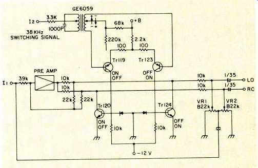
Fig. 3--Multiplex demodulator, using transistor switching circuit with negative
feedback.
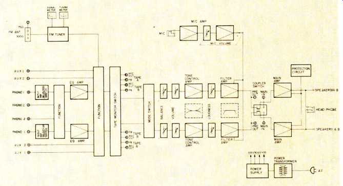
Fig. 4--Block diagram.
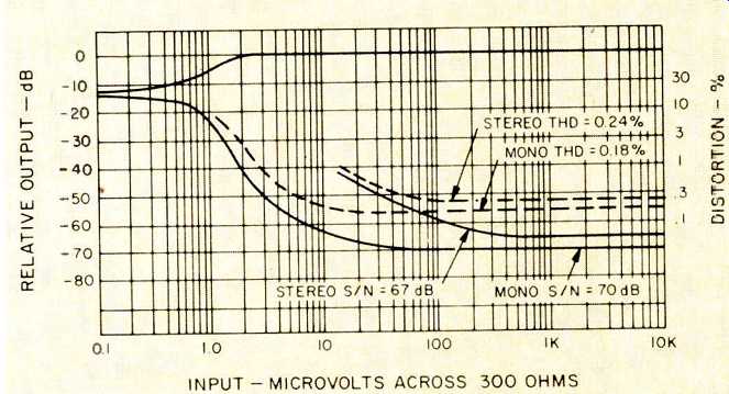
Fig. 5--FM quieting and distortion characteristics.
FM Measurements
Figure 5 is a plot of the more important FM performance characteristics. IHF sensitivity was measured at 1.9 micro volts. With only 3 µV applied, quieting reached 50 dB, and ultimate S/N in mono reached 70 dB for all input signal levels above about 60 pV. Mono THD for strong signal levels was 0.18% at mid frequencies. Transition to stereo occurs automatically at a signal strength of 14 microvolts, a bit too high in our view, but at that signal level, S/N in stereo al ready exceeds 40 dB and improves to a maximum of 67 dB at stronger signal levels. There was absolutely no evidence of sub-carrier product output in stereo, thanks to the active 19 kHz and 38 kHz filters used in the multiplex section of the receiver. Best THD readings for mid-frequencies in stereo operation were around 0.24%.
Stereo FM separation measurements proved disappointing on our sample. As received, mid-frequency separation was only 34 dB as against the 45 dB figure claimed by the manufacturer. We have no doubt but that minor touch-up alignment of the separation controls would have resulted in the unit's living up to published specifications in this regard but we make it a practice to review products as received, since a consumer would not be likely to have the necessary equipment to perform such adjustments. Often, maintaining good stereo separation in FM is difficult because of vibration encountered during long-distance Shipping. This situation does not usually apply to units shipped to an audio dealer, as these units are bulk shipped, strapped to skids, rather than individually. Separation capability over the entire audio range is plotted in Fig. 6, along with THD figures for both mono and stereo operation. The very low reading obtained at 10 kHz in stereo (0.6%) is not of it self terribly significant, since the first harmonic of 10 kHz is 20 kHz, which would be inaudible in any case. What this low reading does convey is the virtual absence of any "beat" effects between the 19 kHz pilot signal and high frequency audio components of the program. Extreme linearity and care in design of the multiplex section is necessary to eliminate such bothersome beats, and Yamaha seems to have done this job in an outstanding manner.
Other measurements taken, but not shown graphically, include alternate channel selectivity of 80 dB as claimed, AM rejection of 60 dB (better than claimed), and capture ratio ranging from 0.85 to 1.1, depending upon signal strengths.
The outstanding 110 dB figures assigned by Yamaha for image, i.f., and spurious rejection could not be confirmed by our test equipment which is limited to 100 dB capability in these specifications, but we can confirm at least 100 dB in each of those cases.
The variable muting adjustment is always a welcome feature on a quality FM product, but in this case we wished that Yamaha had seen fit to lower the threshold to something below the present 10 microvolts. At that signal level, quieting is already in excess of 60 dB and signals are quite listen able-so that it seems a shame to have to defeat the mute feature when desiring to listen to weak signals of lower than 10 µV strength. While we admit that the front-panel mute adjustment balances the aesthetics of the panel, this seldom used adjustment might better have been relegated to the rear panel. Meter action, dial calibration, and even the AFC automatic feature all worked perfectly, with a slight mis-calibration (about 200 kHz) observable near the 108 MHz end of the dial. The multipath output jacks were checked by connecting to an inexpensive audio 'scope which seemed to have enough vertical sensitivity to work well with this feature.
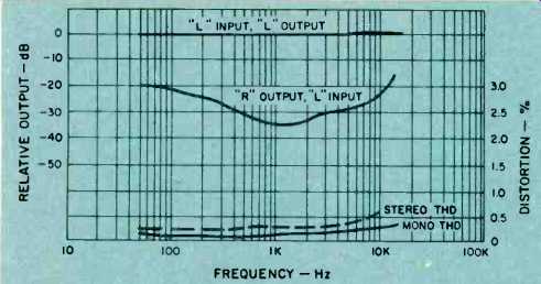
Fig. 6--Separation and distortion versus frequency.
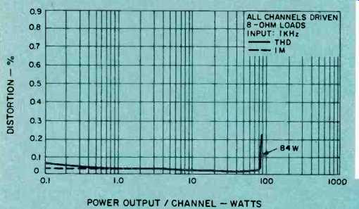
Fig. 7--Harmonic and intermodulation distortion characteristics.
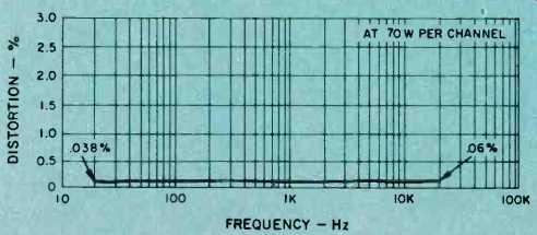
Fig. 8--Distortion versus frequency.
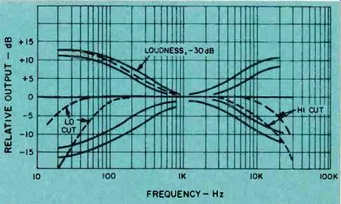
Fig. 9--Tone-control range, and filter and loudness characteristics.
Amplifier Measurements
Although the Yamaha CR-1000 manual and literature were prepared in advance of the date of enforcement of the new FTC power rule, it is to the manufacturer's credit that all the required power information was available, and our power output checks were conducted in accordance with the new required power statements. Thus, as can be seen from Figs. 7 and 8, power output per channel with both channels driven into 8-ohm loads exceeded the 70 watts claimed, reaching 84 watts at mid-frequencies and over 75 watts at the frequency extremes-all at less than 0.1% rated distortion. At anything less than full power output, THD and IM were about 0.03% and 0.02% respectively-figures comparable to separate components and just about as low as our audio test signal itself! Readers should note that we have discontinued the use of "power bandwidth" measurements, as defined by the Institute of High Fidelity. Formerly, IHF power bandwidth meant the frequency extremes at which a product could produce half its rated power at rated distortion. The FTC has, for its part, chosen to use the term "power bandwidth" to define the frequency extremes at which the product can produce its full stated power at or below rated distortion. Since our graphic plot of Fig. 8 conveys this new information directly, and since this FTC definition of power bandwidth is more demanding than the older one, there seems to be no point in continuing to define the older limits and we shall abandon that practice effective with this review.
Variable turnover points in tone controls are desirable and usually are found only in separate components, though this innovation in the CR-1000 leaves a bit to be desired.
The turnover points are somewhat too close to each other (and to the mid-frequency region) to offer very much choice. Even when the lower bass turnover and higher treble turnover are chosen, an attempt to compensate for deficiencies in response at the extremes still results in significant alteration of tonal response towards the mid-range.
This is apparent in the plots of Fig. 9. The low-frequency filters, with their steep slope of 12 dB per octave, are much more effective than the 6 dB/octave hi-filters which do little more than can be accomplished with the aforementioned tone controls.
Preamplifier performance was outstanding. The high overload capability of the phono input circuits is note worthy. A 280 millivolt capability is claimed for the 3 mV sensitivity inputs, and we actually measured a bit better than that before observing first-stage distortion. Equalization was found to be precise within the 0.2 dB claimed.
Listening and Use Tests
Above all, the Yamaha CR-1000 is a powerful receiver.
Hooked up to a pair of low-efficiency speakers capable of excellent bass response when properly driven, the receiver delivered enough clean power to permit us to boldly advance the volume control without fear of reaching "limits." Several hours of high powered use produced no serious overheating of cabinetry or heat sinks-further proof that high powered listening doesn't always mean high average power output when the program material is music. Phono hum was inaudible even at these loud levels and, in fact, our measurements were a fine -70 dB referenced to 3 mV input, with no weighting curve. That would be more like the 80 dB claimed if an "A" weighting curve had been used, and that is about as low as any phono hum we have ever measured or heard using a magnetic-cartridge preamplifier circuit.
The somewhat unusual control layout of the CR-1000 takes a bit of getting used to, but that's probably because we have been so conditioned to the usual row of rotary controls and switches. Slide controls (when they are as smooth acting and easily resettable as these are) actually do afford more precise control and give the user a greater sense of precision adjustment capability. As stated at the outset, the price of the Yamaha CR-1000 is a bit high for what it does, Yamaha CR-1000 is an expensive unit, but this honestly rated, high powered, multi-featured stereo receiver will give a good many separate components a run for their money in terms of performance and control features.
-Leonard Feldman
(Source: Audio magazine, Jan 1975)
Also see:
Yamaha Model R-2000 Receiver (Jul. 1981)
Yamaha Model CR-420 AM/FM Receiver (Nov. 1978)
Yamaha Model B1 Power Amplifier (Aug. 1975)
Yamaha CR-800 receiver (Jan 1975)
Yamaha CA-1000 Integrated Amplifier (Sept. 1974)
This receiver goes well with the Fisher ST-425 Speaker System (Jan. 1975)
= = = =