Manufacturer's Specifications
FM Tuner Section:
Usable Sensitivity: Mono, 11.3 dBf, 2.0 µV @ 300 ohms.
50-dB Quieting: Mono, 14.2 dBf, 2.8µV; stereo, 33.2 dBf, 25 µV.
S/N Ratio: Mono, 85 dB; stereo, 81 dB.
I. f. and Spurious Rejection: 100 dB.
Image Rejection: 70 dB. AM Rejection: 65 dB.
Capture Ratio: Local, 1.2 dB; DX, 2.5 dB.
Alternate Channel Selectivity: Local, 30 dB; DX, 82 dB.
Mono THD: Local, 0.06 percent at 100 Hz or 1 kHz, 0.08 percent at 6 kHz; DX, 0.1 percent at 100 Hz, 0.3 per cent at 1 kHz, 0.7 percent at 6 kHz.
Stereo THD: Local, 0.07 percent at 100 Hz or 1 kHz, 0.09 percent at 6 kHz; DX, 0.1 percent at 100 Hz, 0.5 percent at 1 kHz, 0.8 percent at 6 kHz.
Stereo Separation: Local, 50 dB at 50 Hz and 1 kHz, 45 dB at 10 kHz.
Frequency Response: 30 Hz to 15 kHz, +0.3, -0.5 dB.
Subcarrier Rejection: 65 dB.
Muting Threshold: DX, 14.2 dBf, 2.8 µV
Auto-DX Threshold: 35.3 dBf.
AM Tuner Section:
Usable Sensitivity: 200 µV, loop antenna
Selectivity: 30 dB S/N Ratio: 50 dB
Image Rejection: 40 dB
Spurious Rejection: 50 dB THD: 0.3 percent, 1 kHz
Amplifier and Preamplifier Sections:
Power Output: 150 watts per channel, 8-ohm loads, 20 Hz to 20 kHz.
Rated THD: 0.015 percent.
IM: 0.01 percent for 75 watts into 8 ohms.
Damping Factor: Greater than 60.
Frequency Response: MM phono, 20 Hz to 20 kHz, ± - 0.2 dB; MC phono, 30 Hz to 20 kHz, ± - 0.3 dB; AUX, 5 Hz to 50 kHz, -1.0 dB.
Input Sensitivity: Per new IHF standards, MM phono, 0.2 mV; MC phono, 8.2 µV; high level, 9.8 mV.
S/N Ratio: Per new IHF standards, MM phono, 80 dB; MC phono, 77 dB; high level, 87 dB; main amp in, 100 dB.
Bass Control Range: ± -11 dB at 80 Hz
Treble Control Range: - ±12 dB at 10 kHz
Subsonic Filter Cutoff: 15 Hz, -12 dB per octave
High-Cut Filter Cutoff: 8 kHz, -6 dB per octave
Maximum Loudness Control Attenuation: 20 dB at 1 kHz
General Specifications:
Power Requirements: 120 V, 60 Hz, 550 watts
Dimensions: 21 1 / 4 in. (54 cm) W x 43 / 4 in (12 1 cm) H x 15 1/4 in. (38.7 cm) D.
Weight: 29 lbs., 5 oz. (11.5 kg).
Price: $900.00.
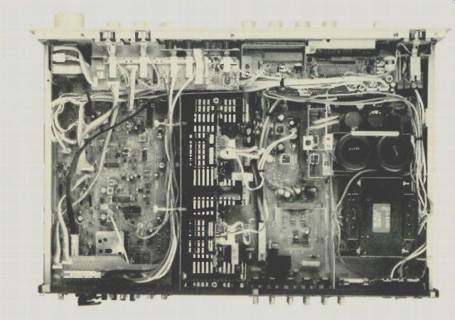

There is so much that is new and different about this top-of the-line Yamaha receiver that it would take this entire issue of Audio to describe all its features, circuitry, and technology.
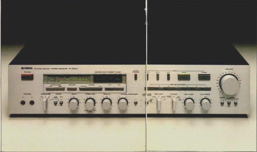
Many of the features which I admired in some earlier Yamaha receivers, such as a separate (and therefore meaningful) continuously variable loudness control, the totally separate recording and program selector switches, and the useful auto-blend FM stereo circuitry (which sacrifices some high-frequency stereo FM separation in return for reduced noise during weak-signal reception) have been retained on this model. And despite the reduced height of the front panel, a good many new features and controls have been added A push-button power switch is at the upper left of the panel.
Next comes a major panel area devoted to tuner functions including a digital display of tuned-to AM or FM frequencies, a multi-segment LED signal-strength/quality indicator (which also serves to display multipath effects by flickering), and additional LEDs to indicate the tuner's mode (local or DX), stereo FM reception, and low or high tuning mode The low and high tuning modes are selected by buttons located just below these last named indicators If the low button is selected, tuner scanning will stop at every received signal. If the high button is chosen, the scanning will stop only where strong signals are received.
Other touch-buttons in this area include one for memory, which is used to preset station frequencies into one of seven programmable memories; a tuning up/down bar, and the FM and AM selector buttons.
One of the new convenience features of the Yamaha R-2000 is represented on the front panel by a button labeled "auto phono " When this button is depressed, the receiver will automatically switch over to phono input the moment your phono cartridge stylus sets down upon a record being played, no matter what other program source you had manually selected previously. Readers who shun gimmickry may find this feature to be a bit much, but think about it for a while: you just might grow to like the idea of being able to override, say, tuner or tape by simply starting a record going on your turntable! The upper right section of the panel is devoted to five pro gram selector touch buttons, the master volume control (accurately calibrated in dB below full volume), and the aforementioned seven preset buttons which can be used to memorize seven FM as well as seven different AM station frequencies. All remaining controls and functions are located along the lower section of the front panel. There we find a pair of stereo phone jacks at the left. a speaker selector switch; bass. midrange (or presence) and treble tone controls; a new control identified as a spatial expander with an associated on/off switch; a pre/main amp coupler switch; the record-out selector (with tape copy as well as signal source positions); a phono switch which selects either MM or MC inputs and offers three values of loading capacitance and loading resistance combinations for MM cartridges: a rotary balance control: the separate loudness control referred to earlier; a stereo/mono mode switch; a muting on/off-mono switch, and an auto/local switch.
The presence or midrange tone control is augmented by a three-position, concentrically mounted switch just behind it which selects the center frequency to be boosted or cut by the presence control. The center frequencies are an octave apart, at 800 Hz, 1.6 kHz, and 3.2 kHz. The spatial expander control introduces circuitry which, by manipulating phase and amplitude and by cross-feeding of channels, seems to extend the stereo sound field beyond the space between the two loudspeaker systems used with the receiver. The idea is not new, but this is the first time I have seen such a feature incorporated in a receiver.
The pre-main coupler switch simply allows the user to "break" the signal path between the output of the preamp/control section and the main amp section of the receiver so that accessory devices may be interposed between these sections or so that the preamp control section can be used to drive a separate power amplifier, if desired. Normally, such facilities have been provided on receivers through rear-panel wire jumpers or slide switches. Yamaha makes it more convenient by bringing the switch up front. Upon reviewing the list of controls, I note that I overlooked the subsonic and high-cut filters located between the speaker selector switch and the bass control. Small wonder, considering how many controls and features Yamaha has man aged to cram on this relatively slim panel. For all of that, the new design does not leave the impression of being cluttered or over done. The panel is executed with the same good taste that characterized earlier Yamaha receiver and amplifier designs.
Up to three sets of speakers can be connected to this receiver via a new kind of speaker terminal which is a real pleasure to use. Simply insert the stripped end of the speaker wire into a large hole, twist the entire terminal a quarter-turn, and the wire is locked in place, making good contact with the output circuitry of the amplifier section. One switched and two unswitched a.c. receptacles are located to the right of the speaker terminals.
while to their left is the usual array of input and tape-out jacks (there are two full tape-monitor loops on this receiver), 75-ohm unbalanced and 300-ohm balanced FM antenna terminals, external AM and ground terminals, the previously discussed preamp-out /main amp-in jacks, and a chassis ground terminal.
The AM loop antenna is provided in a separate accessories envelope (a good idea in view of the number of damaged or broken ones I have unpacked over the years) and can be connected to a bracket on the rear panel or maintained at a distance from the receiver itself if reception conditions so dictate Despite the fact that the front panel provides for selection of either MM or MC phono cartridge preamp circuitry, there is only one pair of phono inputs on the rear panel. It is, in other words, an either/or proposition.
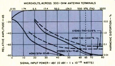
Fig. 1-Mono and stereo quieting and distortion characteristics.
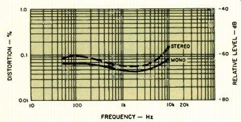
Fig. 2-Stereo FM distortion vs. frequency.
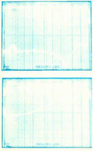
Fig. 3-Stereo FM frequency response and separation.
Fig. 4 -Effect of auto-blend control on stereo FM separation.
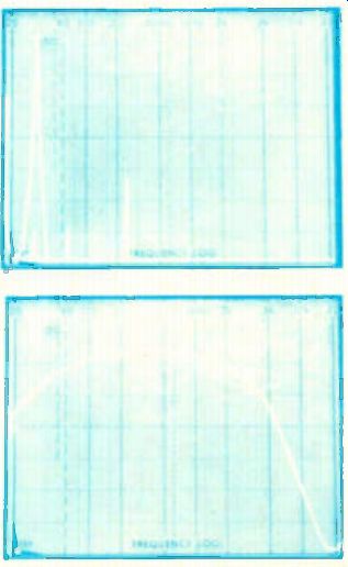
Fig. 5-Stereo FM crosstalk components, 5-kHz modulating signal.
Fig. 6-Frequency response, AM section.
Circuit Highlights
What Yamaha calls an X-Power Amplifier is apparently a two level supply voltage system in which a high-speed comparator circuit monitors the level of the envelope of the audio signal, switching in the high-voltage supply when it is required to handle high-level music peaks. Additional fast-rise detectors are used to detect fast musical transients and to turn on the higher voltage supply a little before it is required so that switching distortion does not occur. A delay is also incorporated in the switch-down from high to low voltage as well, to eliminate the possibility of any switching distortion during that sequence. The system is said to be fast enough and precise enough so that even a single cycle at 100 kHz at full rated output (150 watts per channel) will not cause distortion. The whole idea is, to me, somewhat reminiscent of the Soundcraftsmen "Class H" idea, introduced a couple of years ago, and of the Carver magnetic field amplifier. As a result of this X-Power scheme, Yamaha has managed to build a lot of amplifier power into a fairly small space, thanks to the improved efficiency resulting from these circuit techniques.
As for the tuner section. I hasten to point out that all appearances notwithstanding, this is not a frequency synthesized tuner circuit nor does Yamaha claim it to be one. The manufacturer points out that one of the disadvantages of true frequency synthesized tuners is that the extra local oscillators and divide-down circuits in such tuners actually add noise to the signal and limit the ultimate signal-to-noise performance attainable by the tuner section. Instead of frequency synthesis, the R-2000 uses a microcomputer and memory to provide the desired station frequency in digital form. This digital code is applied to a D/A converter that puts out a d.c. voltage which corresponds to the digital frequency information. The control voltage governs both the front-end oscillator and tuned-to frequencies, while a special "Station Locked Loop" system makes corrections to the control voltage if the received station is not perfectly tuned in. In short, what we really have here is a rather sophisticated form of a.f.c. circuitry.
Yamaha's argument concerning performance limits of frequency synthesized tuners was, in fact, true up until a few months ago, when such manufacturers as Sony came up with methods which overcome the previous limitations of such tuners. Today, there are true frequency synthesized tuners which do fully as well in the S/N department as does the tuner section of the R-2000. This does not, however, detract from the fact that the tuner section of the R-2000 provides all of the benefits of true frequency synthesis (presets on AM and FM, automatic up and down scanning, and precise center-tuning) without having to resort to actual frequency synthesis.
Tuner Section Measurements
Figure 1 plots the quieting and distortion (1 kHz) characteristics of the tuner section of the R-2000 in mono and stereo. I measured a very outstanding 85 dB of quieting in mono and an impressive 75 dB in stereo (the latter most probably limited by my own test equipment, which has that much residual noise of its own in the stereo mode). THD for a 1-kHz, 100-percent modulating signal in mono was a very low 0.047 percent, rising only very slightly to 0.06 percent in stereo. Perhaps even more importantly, THD remains extremely low at all test frequencies, as can be seen from the plots in Fig. 2.
Usable mono sensitivity measured 13.2 dBf (2.5 µV), a bit poorer than claimed, while in stereo it required a signal level of 31 dBf to reach usable sensitivity. The 50-dB quieting point occurred with only 2.8 µV (14.2 dBf) of signal, exactly as claimed by Yamaha. But if the tuner section was not put in the DX position by a weak signal, it required a full 40 dBf to reach the 50-dB quieting point. Here I have a criticism of the design philosophy of this tuner section. In my opinion, the user should have the option to choose DX or Local (in reality, "broad" or "narrow" if.) in addition to having the automatic circuits making that decision.
Capture ratio in the Local position measured exactly 1.2 dB as claimed, and alternate channel selectivity in the DX position measured a full 85 dB as against 82 dB claimed. Distortion at the other two test points (100 Hz and 6 kHz) measured 0.065 percent and 0.06 percent in mono and 0.09 percent and 0.075 percent in stereo, all excellent results for a tuner or receiver and show the very highest quality.
Stereo separation and frequency response of the FM tuner section are plotted on the spectrum analyzer 'scope photo of Fig. 3. In this photo and in Figs. 4, 6, 9, 10 and 11, the frequency sweep is logarithmic from 20 Hz to 20 kHz, while in Fig. 5 the sweeps are linear over the same frequency range. In all of these 'scope photos, vertical sensitivity is 10 dB per division. Spot measurements at specific test frequencies of 100 Hz, 1 kHz, and 10 kHz revealed separation figures of 57 dB, 59 dB and 46 dB respectively - all significantly better than claimed by Yamaha. Figure 4 shows what happens to stereo FM separation when the auto-blend circuit operates. In return for reduced high frequency noise, the blending reduces separation at high frequencies substantially (it is less than 10 dB at 5 kHz). Figure 5 shows how near-perfect the Yamaha multiplex decoder section is, insofar as the generation of crosstalk distortion products in non-modulated channels is concerned. Here we see a reference signal at 5 kHz (tall spike at left) from the modulated output and, in a sweep of right-channel output, we see the shorter 5-kHz signal contained within the tall spike (more than 60 dB of separation); the only other significant products seen to the right are some second-order distortion of the 5-kHz signal, the expected 19-kHz pilot residual signal, and a minute amount of 38-kHz sub-carrier at the right, surrounded by small amounts of side bands at 33 kHz and 43 kHz. No other spurious products are produced by this very "clean" MPX decoder circuit. All of the secondary specifications (the various rejection figures) met or exceeded published specifications for the FM section of this receiver.
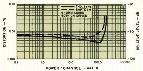
Fig. 7-Power output vs. THD.
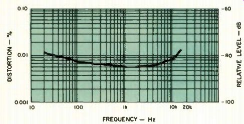
Fig. 8-Distortion vs. frequency.
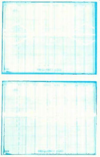
Fig. 9-Range of bass and treble control circuits.
Fig. 10-Range of presence control with each of the three center frequencies.
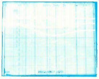
Fig. 11 -Action of the continuously variable loudness control.
The frequency response of the AM section is plotted in the 'scope photo of Fig. 6 and turns out to be not much better than is typical of most stereo receivers, with -6 dB roll-off points occurring at around 50 Hz and 3 kHz.
Amp/Preamp Measurements
The power amplifier section of the R-2000 receiver delivered 170 watts per channel before reaching the rated distortion figure (THD) of 0.015 percent Even at low output levels (below 1 watt), THD was well below 0 01 percent, indicating virtually complete absence of any notch or switching distortion. In fact, my results, depicted in graphic form in Fig. 7, are probably limited by the residual distortion in my signal-generating equipment. Yamaha's engineering department supplied me with their own plots (not shown) which showed even lower distortion levels and which I have no reason to disbelieve in view of my laboratory findings.
COIF IM distortion measured less than 0.01 percent, while IHF IM distortion, which correlates well with the way the amplifier actually sounds, measured an extremely low 0 031 percent at rated output. Damping factor measured 71 at 50 Hz (8-ohm load reference), while dynamic headroom was a fairly high 2.1 dB THD versus audio frequencies is plotted in Fig. 8 and is again as low as my test equipment would permit measuring.
Figures 9 and 10 show the remarkable flexibility and wide range of adjustment afforded by Yamaha's unique three-control tone control system. Notice that the bass and treble controls, when in the extreme boost or cut position (Fig. 9), do not continue to boost or cut extreme low or high frequencies outside the audio spectrum, but reach a peak and then head back towards the zero axis, unlike most conventional bass and treble control circuits I think this is a much more intelligent approach to tone control design. Note, too, that the three center-frequency mid range control's actions, added to those of the bass and treble control, give this tone control system about the same flexibility that one might expect from a three-band full parametric EQ1 Figure 11 shows the range of control and response of the separate loudness control offered by Yamaha on this and many other receivers. The user adjusts the volume control for maxi mum or '*lifelike" loudness levels and then, using this secondary loudness control, can reduce that level by up to 20 dB or so, achieving proper Fletcher-Munsen loudness compensation in stead of the arbitrary (and generally incorrect) bass and treble boost usually provided by on-off type loudness controls that are tied into the volume control. The way Yamaha handles this control is the way it should be handled, in my opinion.
Input sensitivities measured 0 2 mV for the MM phono inputs, 8 2 µV for the MC inputs. and 10 mV for the high-level AUX inputs (all referred to 1-watt output). The MM phono input was able to handle signal levels of 350 mV (at 1 kHz) before significant overload was observed, while in the case of the high-gain MC input, overload occurred with input levels of 21 mV. Signal to-noise for phono measured 85 5 dB for the MM inputs (referred to 5 mV in and 1 watt out), 75 dB for the MC input (referred to 0.5 mV in and 1 watt out). and 89 dB for the AUX inputs (referred to 0.5 V in and 1 watt out). These are, to say the least, excellent figures; typically from 6 to 10 dB better than I usually measure on receivers. At minimum volume setting, hum and noise was 110 dB below 1-watt output. All S/N readings were taken with an A-weighting network, as usual. Overall frequency response, via the AUX inputs, was within 1 dB of flat from 5 Hz to 50 kHz.
Use and Listening Tests
The Yamaha R-2000 is, without a doubt, one of the finest receivers I have ever had the pleasure of testing and auditioning.
Its power output capabilities are awesome and rather hard to believe when one looks at the relatively small volume of the product. While I may take issue with some of the claims or even circuit approaches taken by its designers (as in the case of their argument in favor of their FM/AM tuning approach versus true frequency synthesizers), I cannot fault the product's performance itself. It is in every sense excellent, both in terms of the way the controls handle and the way in which it reproduces sound.
To be sure, my pet peeve (the mono/stereo related muting switch) is an annoyance, as is the non-defeatable auto-blend/ auto-DX switching, but for the typical receiver purchaser these may represent sensible approaches to problems that new comers to audio might not otherwise be able to cope with easily.
Aside from its excellent sonic capabilities, one gets the feeling that the folks at Yamaha must have sat down one day a year or so ago, either in Hamamatsu, Japan or in Buena Park, California, and said to themselves, "What are all the nice features we can put into our next top-of-the-line receiver without pricing our selves out of the market, and what new circuit approaches can we come up with so that the resulting receiver isn't too heavy to lift?" From my experience with the R-2000 thus far. Yamaha has come up with some valid answers as well as the question.
-Leonard Feldman
(Source: Audio magazine, Jul 1981)
Also see:
Yamaha Model CR-1000 Stereo FM Receiver (Equip. Profile, Jan. 1975)
Yamaha Model CR-420 AM/FM Receiver (Nov. 1978)
Yamaha Model B1 Power Amplifier (Aug. 1975)
Yamaha CR-800 receiver (Jan 1975)
Yamaha CA-1000 Integrated Amplifier (Sept. 1974)
This receiver goes well with the Fisher ST-425 Speaker System (Jan. 1975)
= = = =