
MANUFACTURER'S SPECIFICATIONS:
FM Tuner Section:
Usable Sensitivity: 10.3 dBf (1.8 pV) mono.
50-dB Quieting: Mono, 16.1 dBf (3.5 pV); Stereo, 38 dBf (43.5 NV).
Image Rejection: 50 dB.
I.f. & Spurious Rejection: 75 dB.
AM Suppression: 56 dB.
Capture Ratio: 1.0 dB.
S/N Ratio: Mono, 77 dB; Stereo, 71 dB.
THD: Mono, 0.15 percent @ 100 Hz & 1 kHz, 0.3 percent at 6 kHz; Stereo, 0.25 percent at 100 Hz & 1 kHz, 0.8 percent at 6 kHz.
Sub-Carrier Rejection: 40 dB.
Frequency Response: 30 Hz to 15 kHz, +1.0, -3.0 d B.
Stereo Separation: 40 dB at 1 kHz, 30 dB at 100 Hz&10kHz.
Muting Threshold: 19.2 dBf (5 NV).
Selectivity: 65 dB.
AM Tuner Section IHF Sensitivity: 18 NV.
Selectivity: 20 dB.
S/N Ratio: 50 dB.
Image & I.f. Rejection: 40 dB.
Spurious Rejection: 50 dB.
THD (30 percent Modulation): 0.6 percent.
Amplifier Section:
Power Output: 22 watts per channel, 8-ohm loads, 20 Hz to 20 kHz.
Rated THD: 0.05 percent.
IM Distortion: 0.05 percent.
Damping Factor: 40.
Noise Distortion Clearance Range for 0.1 percent, 8 ohms, 20 Hz to 20 kHz:
From 100 mW to 22 W, phono in to speakers out, volume at-20 from maximum.
Input Sensitivity: Phono, 2 mV; High Level, 120 mV.
Phono Overload: 110 mV.
Frequency Response: Phono ±0.5 dB re: RIAA; High Level, 20 Hz to 20 kHz ±1.5 dB.
Bass Control Range: ±12 dB at 50 Hz.
Treble Control Range: ±11 dB at 20 kHz.
Low Filter Cutoff: 10 Hz at 12 dB/ octave.
High Filter Cutoff: 10 kHz, at 6 dB/ octave.
S/N Ratio: Phono, 91 dB re: 10 mV in, "A" weighted; High Level, 97 dB, "A" weighted.
General Specifications:
Power Consumption: 130 W at 120 V, 60 Hz.
Dimensions: 17 3/4 in. (45 cm) W x 6 1/3 in. (16 cm) H x 12 3/4 in. (32.4 cm) D.
Weight: 19 lbs. (8.6 kg) .
Price: $290.00.
--------------------

-------- Rear view
With high-efficiency speakers making a comeback, the budget-minded audiophile is often hard-pressed to find a relatively low-powered, low-priced integrated receiver which offers the control features and flexibility commonly found on higher powered, higher priced models. The Yamaha CR-420 is just such a receiver and, in fact, some of its front panel features are not to be found in many competitive products from other sources regardless of their price and power ratings.
The rather narrow dial opening along the upper section of the front panel of this unit has linearly calibrated FM and conventional AM frequency scales, with FM frequencies de lineated at every 0.5 MHz. To the right of the frequency scales are indicator lights for AM, FM, and stereo FM, while, over at the left, a single meter serves as a signal-strength indicator for AM tuning and as a center-of-channel tuning indicator when FM listening is selected. Controls along the center section of the panel include the usual bass and treble knobs (step-type), a separate continuously variable loudness control (about which more in a moment), separate input and record-output selector switches (whereby the listener can direct any program source to the speakers, while any other program source is channeled to the record output jacks), dual concentric volume and balance controls, and a frequency tuning knob coupled to a flywheel.
Controls along the lower edge of the front panel include a Power On/Off push-button switch, "A" and "B" speaker buttons, a high-cut filter switch, a tuner selector (for AM or FM selection), a Mono/Stereo Mode switch, and an FM Muting On/Off switch. With the muting circuit defeated, only mono reception is possible.
The rear panel of the CR-420 is equipped with two sets of spring-loaded speaker terminals, a pair of a.c. convenience outlets (one switched, the other unswitched), pairs of phono, AUX and tape-input jacks, a pair of tape-out jacks, and antenna terminals for connection of 75-ohm, 300-ohm, or external AM antennas. As shipped, a shorting bar is connected between the AM antenna terminal and one terminal of the 300-ohm antenna connection. In this way, the connected FM antenna (indoor or outdoor) also is made to serve as an AM antenna. If an AM external antenna is found to be required, the shorting bar must be removed.
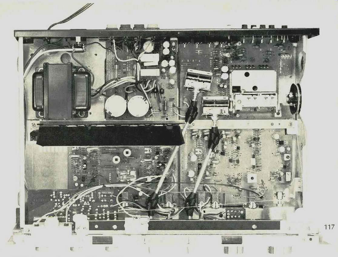
------Top, inside view
Circuit Configuration
A block diagram of the circuit layout of the Yamaha CR-420 is shown in Fig. 1. A junction FET is used for r.f. amplification in the FM front end, as is a three-section variable capacitor. The i.f. stage includes a two-element ceramic filter and a two-stage direct-connected amplifier. The two-element ceramic filter and current limiter compose a three-stage differential amplifier. A wide-range, modified balanced-type detector is used for FM demodulation, and this is followed by a negative-feedback, phase-lock-loop, multiplex stereo decoder circuit. The AM tuner section consists of an untuned r.f. first stage, a self-oscillating converter, a ceramic filter for the i.f. section, and a peak type detection circuit.
The audio section includes a two-stage, direct-coupled equalizer amplifier; a negative feedback-type, RC tone control circuit; a differential-input stage to the power amp section, and a single-ended, push-pull, output-capacitorless power amplifier stage with a speaker protection circuit. Auxiliary circuits include a recording-output selector, mode switch, high filter, dual speaker system selector, and two headphone jack circuits.
Note the use of a separate continuously variable loudness control, apart from the regular master volume control, which is located at an earlier point in the block diagram (ahead of the tone control circuitry). With the loudness control set to its maximum clockwise position, there is no loudness compensation. In use, the listener would adjust the main volume control so that the given program source sounds as loud as it might in a "real life" situation. Then, the loudness control is rotated counterclockwise and, as this is done, overall listen attenuated, the bass treble response are progressively accentuated to take care of the well-known Fletcher-Munson hearing effect. In arranging the controls in this manner, Yamaha offers meaningful loudness compensation, regardless of the level of the incoming program source or the efficiency of the speakers with which the receiver is ultimately used. In the more commonly found volume/loudness switch arrangement, effectiveness of the loudness compensation is purely a matter of chance (depending upon in coming signal levels) and rarely works as it should, so Yamaha has done something worthwhile and very special here.

Fig. 1--Circuit block diagram.
FM Tuner Section Measurements
Major FM tuner section characteristics are plotted in Figs. 2, 3, and 4. Usable sensitivity measured 1.7 NV (10.3 dBf) in mono and 8.0 pV (23.3 dBf) in stereo, the stereo threshold or switching point. The 50-dB quieting point for mono was 13.2 dBf (2.5 pV) as against 16.1 dBf (3.5 pV) claimed, while in stereo the 50-dB quieting point was obtained with signal in puts of 35.6 dBf (33 pV) as against 38 dBf (43.5 pV) claimed.

Fig. 2--FM mono and stereo quieting and distortion characteristics.
Fig. 3--FM frequency response and stereo separation. (Each vertical division equals 10 dB.)

Fig. 4--Distortion vs. frequency in the FM section.

Fig. 5--AM frequency response.
Best quieting in mono measured 76 dB; 70 dB was the case in stereo. Distortion, for a 1-kHz signal measured an extremely low 0.06 percent in mono and an almost equally low 0.07 percent in stereo, as indicated in the curves of Fig. 2. Figure 3 is a plot of frequency response (upper trace), which was virtually flat right out to 15 kHz, and separation (lower trace) which measured 54 dB at mid frequencies, 45 dB at 100 Hz, and a very high 43 dB at 10 kHz. Figure 4 is a plot of mono and stereo harmonic distortion over the frequency spectrum of interest. Even at the difficult 10-kHz test point (measurement standards require that THD be measured only up to 6 kHz), stereo THD was still a low 0.4 percent. These measurements were all made with the prescribed band-pass filter in the circuit, and so the rather minimal sub-carrier product rejection capability of the receiver (only 47 dB) does not contribute to the distortion readings.
Capture ratio measured 1.2 dB, while alternate channel selectivity measured exactly 65 dB as claimed. Image rejection was on the low side, at 50 dB, while i.f. rejection measured 78 dB and spurious rejection was 80 dB, somewhat better than claimed. AM suppression measured 56 dB as claimed. Muting threshold measured 20.8 dBf (6 NV), while stereo switching occurred at around 23.3 dBf (8.0 pV), a bit higher than claimed.
Figure 5 is a spectrum-analyzer sweep-frequency plot of the frequency response of the AM section of this receiver.
While off-hand it seems nothing to write home about, it actually is somewhat better than the run-of-the-mill AM tuner responses we have been measuring of late, with high-end roll-off beginning above 3 kHz as against the "usual" 2.0 to 2.5 kHz cut-off points we have been finding lately.

Fig. 6--Distortion vs power output at 1 kHz.
Fig. 7--Harmonic distortion vs. frequency.
Amplifier Section Measurements
The power amplifier section of the Yamaha CR-420 delivered nearly 34 watts of power per channel into 8 ohm loads at a test frequency of 1 kHz. At 20 Hz, the rated harmonic distortion figure of 0.05 percent was reached when the amp was putting out 31 watts per channel, while at the high end, even greater power was available before reaching rated THD.
Based upon FTC rules, the amp section could have been rated at 31 watts per channel instead of the 22 watts per channel which Yamaha publishes. At the published rated output, THD for 1 kHz measured only 0.008 percent, while IM distortion was almost as low, at 0.009 percent. These characteristics are plotted in Fig. 6, while IM and THD versus frequency are graphed (for rated output levels) in Fig. 7.
A word is in order concerning one of Yamaha's specifications (which appears in the introduction to this report) which may not be familiar to readers of Audio. It is called NDCR and it stands for Noise Distortion Clearance Range. Yamaha maintains that most of the noise and distortion claims for amplifiers, as usually published, do not tell the prospective user what levels of noise and distortion he or she is likely to encounter under actual use. That is because the S/N ratios are quoted with respect to full rated output (with the volume control at maximum, where it is seldom if ever set). Their NDCR spec (0.1 percent from 100 mW to rated output, via the phono input, with volume control set-20 dB below maximum) attempts to correct this by stating that over the range given, the combination of noise and harmonic distortion will not exceed 0.1 percent. (In terms of noise, 0.1 percent is equivalent to a-60 dB figure).
As a matter of fact, the new IHF Standards for Amplifier Measurements (IHF-A-202), discussed in the June, 1978, issue of Audio, does deal with this problem in a very positive way.
The S/N figures which we measured for the Yamaha CR-420 were measured using the new IHF Standard and, if they seem not to correspond with Yamaha's other published specs (especially as regards input sensitivity and S/N), bear in mind that we are now using input reference levels of 5 mV (for phono) and 0.5 V (for high level inputs) and output reference levels of 1.0 watt. This necessitates reducing the main volume control settings in a manner not unlike that suggested by Yamaha in their NDCR specification.
In any event, damping factor for the power amp (now measured specifically at 50 Hz) was 51.4, well above the 40 claimed. Dynamic headroom measured 3.29 dB, while clip ping headroom measured 2.2 dB above rated power. Frequency response, measured via the high-level AUX inputs, was down 3 dB at 8 Hz and 100 kHz. The amplifier has a built-in (non-switchable) sub-sonic filter with a nominal cut off point of 10 Hz. RIAA equalization was accurate to within +0.5 and-0.0 dB. Input sensitivity in phono (for 1-watt output, remember) was 0.43 mV, while for the high level inputs it was 22.4 mV. S/N ratio in phono ("A" weighted, referred to 5-mV input and 1-watt output) was 80 dB, while for the high level inputs (referred to 0.5 volts in, 1 watt out) was 84 dB.
Figure 8 is a spectrum-analyzer plot of bass and treble tone control range. Note, that while only a fixed turnover is provided for each of these controls, the turnover points are set a bit further away from the center of the audio spectrum than usual- a feature with which we heartily concur if the price of the set precludes having selectable turnover points.
The action of the separate loudness control is depicted by the curves of Fig. 9. Total audible adjustment range of this secondary control is some 20 dB (at mid frequencies), enough to lower overall listening levels from real-life sound pressure levels to "background music levels" for which loudness compensation is actually required.

Fig. 8--Bass and treble control range.

Fig. 9--Continuous loudness control range on the Yamaha CR-420.
Listening and Use Tests
As we have already suggested, if you examined the features and control panel of this receiver, you would never guess either its price or its power output capability. For the audio enthusiast who needs a lower powered receiver with as many control features as possible, the Yamaha CR-420 is a worthy contender. Two sets of tape monitor circuits might have been useful here, especially if the owner hopes to do some tape dubbing, but offsetting that omission is the very handy separate selector arrangement which lets you record one program on tape while listening to another.
The power reserve of the CR-420 is surprising. We had no difficulty driving relatively inefficient speaker systems to surprisingly high SPLs. Phono overload (measured at 140 mV as against 110 mV claimed) never posed a problem, and phono reproduction was clean and tight, responding well to fast transient material in some of the direct-to-disc records which we used for auditioning purposes.
In recording stereo FM programs using the CR-420, it would be advisable to switch on the MPX filter on your tape deck (if it has one), since the inaudible but fairly high sub-carrier output products of the tuner selection might otherwise "confuse" your Dolby circuitry.
The loudness control arrangement is particularly effective, and the bass and treble controls, used in moderation, helped to tweak a somewhat unbalanced sonic situation without exaggerating response at frequencies that required no correction. All in all, a tastefully designed and well executed receiver at a price that cannot be faulted.
--Leonard Feldman
(Audio magazine, Nov. 1978)
Also see:
Yamaha Model CR-1000 Stereo FM Receiver (Jan. 1975)
Yamaha R-9 Receiver (Dec. 1985)
Yamaha Model B1 Power Amplifier (Aug. 1975)
Yamaha CR-800 receiver (Jan 1975)
Yamaha CA-1000 Integrated Amplifier (Sept. 1974)
Yamaha Model CT-7000 Stereo FM Tuner (Dec. 1975)
This receiver goes well with the Fisher ST-425 Speaker System (Jan. 1975)
= = = =