MANUFACTURER'S SPECIFICATIONS
Rated Output Voltage: 2.0 V rms.
THD at Rated Output, 20 Hz to 20 kHz: Less than 0.04 percent.
S/N Ratio (IHF "A" Weighted): Phono 1 (MM), 90 dB re: 10 mV; Phono 2 (MC), 78 dB re: 1 mV, High Level, 91 dB.
Input Impedance: Phono 1, 47 kilohms shunted by selectable 150, 225, or 420 pF; Phono 2, 50, 200, or 500 ohms, selectable, shunted by less than 20 pF; High Level, 50 kilohms.
Input Sensitivity: Phono 1, 2.0 mV; Phono 2, 0.2 mV; High Level, 200 mV.
Frequency Response: Phono 1 & 2, RIAA ±0.3 dB; High Level, 20 Hz to 20 kHz, ±0.1 dB.
Maximum Output at Clipping: 10 V into 10 kilohms.
Phono Overload: Phono 1, 120 mV; Phono 2, 12 mV.
Bass Control Range: ±7 dB or ±9.5 dB at 20 Hz.
Treble Control Range: ±8.5 dB or ±10 dB at 20 kHz.
Low Filter Characteristics: -18 dB per octave, cut off frequency of 15 Hz.
Headphone Amplifier Output: 200 mW into 8 ohms, 20 Hz to 20 kHz, with less than 0.07 percent THD.
Headphone Amp S/N: Better than 90 dB re: 200 mW output.
General Specifications
Power Requirements: 120 V, 60 Hz, 8 watts.
Dimensions: 19-in. (48.3 cm) W x 3 1/2 in. (8.9 cm) H x 8-in. (20.3 cm) D.
Weight: 10 lbs. (4.5 kg).
Price: $499.95.
------------
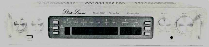
Just one quick look at the front panel of the new Phase Linear Model 3000-II is enough to tell you that the company has come a long way in terms of industrial design compared with its earlier, rather cumbersome looking units of a few years ago. And, even if you were one of those who admired the technology offered by earlier Phase Linear products (and we can be numbered among such admirers), you'll be pleased to see that improved outward styling has not resulted in any internal circuit compromises. In fact, the preamp circuitry of the 3000-II is better than ever.
The light-colored, two-tone panel of the 3000-II is distinguished by a darker colored recessed area which contains all of the switching facilities built into this unit, with the exception of the power On/Off button at the lower left of the main panel area. At the left end of the recessed panel area are three pushbuttons. Two of these select turnover frequencies for the tone controls (50 Hz and 150 Hz for the bass, 2 kHz and 5 kHz for treble), while the third serves to bypass the tone circuits entirely. Symmetrically positioned buttons at the right of the recessed panel area handle mono/stereo selection, loudness circuitry, and -20 dB audio muting. Arranged horizontally and still within the recessed area are a low-filter button (with an amber LED above it that lights when the circuit is activated), six tactile pushbutton switches that operate CMOS-logic selector switches for program selection, and four matching pushbutton switches for the two tape monitor circuits and for dubbing from tape 1 to tape 2 or vice versa. Green LED indicators above the program selectors denote program source, while amber LEDs above the monitor and dubbing switches let you know what's happening in that area.
The bass and treble tone controls, step-calibrated, are on the main panel surface at the left, while at the right end of the panel are a balance control and a 22-step volume control calibrated in dB of attenuation. A headphone output jack, powered by its own amplifier, is also located in this area.
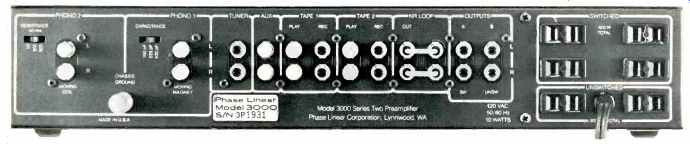
Input and output jacks are logically arranged and designated on the rear panel of the 3000-II. The moving-coil (MC) inputs have a slide switch near them which selects the required resistive loading for such cartridges (50, 200, or 500 ohms), while the moving-magnet phono inputs (MM) have an associated slide switch which selects capacitance values of 150, 225, or 420 pF which are then placed in parallel with the 47 kilohm resistive load appearing at these inputs for optimum match of MM cartridges. In addition to the high-level, tape-in, and tape-out jack pairs, there are input and output pairs labeled NR (Noise Reduction) Loop which come with interconnecting jumpers, but which may be used to interpose noise reduction (or other accessory) units such as Dolby, dbx, or, as Phase Linear is quick to point out, their own Model 1000 auto-correlator noise reduction device. Switched and unswitched pairs of output jacks are provided, the former switched off whenever headphones are connected to the front panel phone jack. A total of six a.c. convenience outlets (4 switched, 2 unswitched) and a chassis ground terminal complete the rear panel layout.
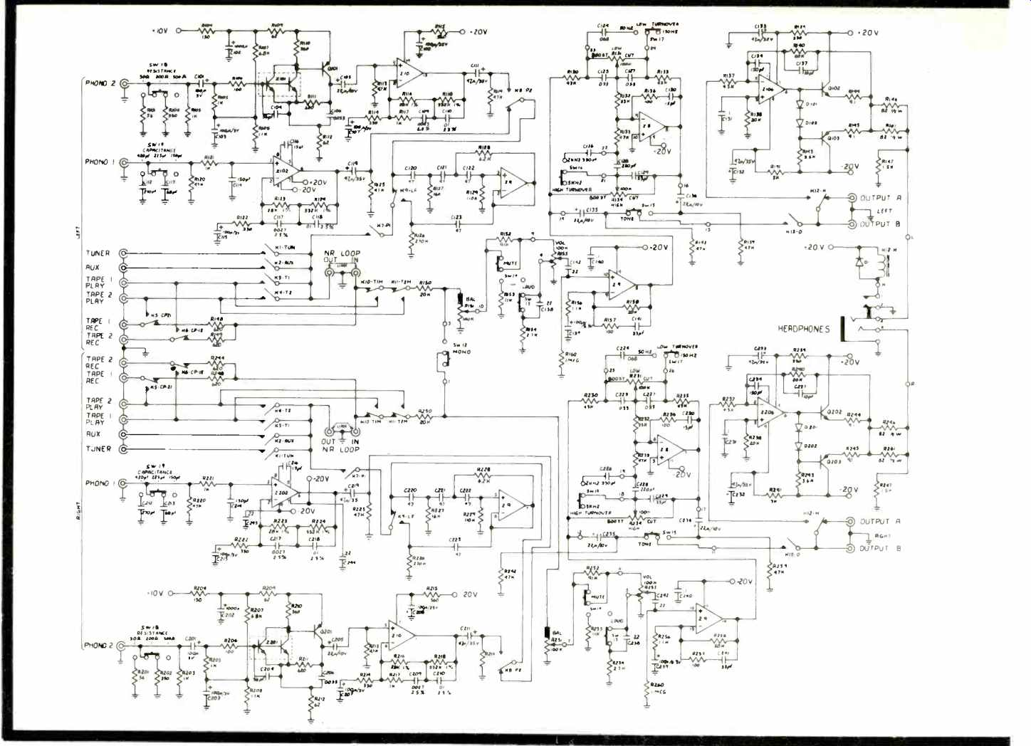
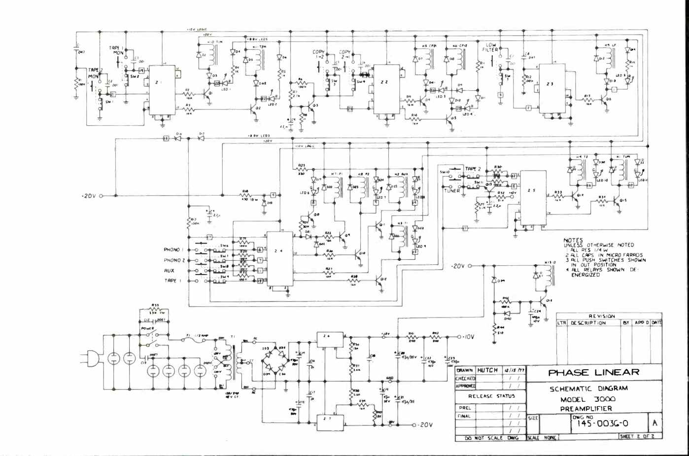
Fig. 1--Complete schematic of the Phase Linear 3000-11.
Circuit and Construction Highlights
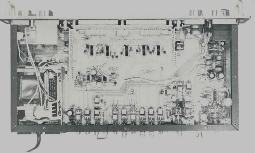
A complete schematic diagram of the 3000-II is reproduced in Fig. 1. Gain and equalization for the MM and MC cartridge inputs are separately accomplished by ICs Z-102 or Z-10. Active tone controls consist of Z8 and its associated feedback elements which are arranged in a modified form of the classical Baxandall circuitry. Gain of the high-level signal section is 20 dB, provided by a gain block made up of Z9 and its feedback network.
All relays used for signal routing are controlled by CMOSD flip flops either dual units Z1, Z2, and Z3 or quad units Z4 and Z5. Tactile pushbuttons (SW1-SW11) are used to control the clock input lines on the dual-Ds and the D-inputs on the quad-Ds. Transistors Q3 and Q13 are used for sequencing during power turn-on, along with networks R1-C1 and R12-C8. Integrated circuits Z6 and Z7 comprise a dual-tracking regulator system providing ±20 volts d.c. for all ICs except the CMOS circuitry which operates from-10 V d.c. regulated by Zener diode D18. Delayed turn-on is accomplished by the R-C charge time of R45 and C24, while the quick turn-off time is fixed by discharge time constant R44-C24.
A major feature of the CMOS-logic selector switch is its ability to remember which functions have been selected even with the power switched off. For the memory circuits to remain active the a.c. power cord must remain connected to an energized outlet, but the power switch need not be on. In situations where control of the 3000-II is to be done by switching power to its a.c. line cord (as, for example when using an external timer), the logic circuits will automatically select Tuner as the program source.
Laboratory Measurements
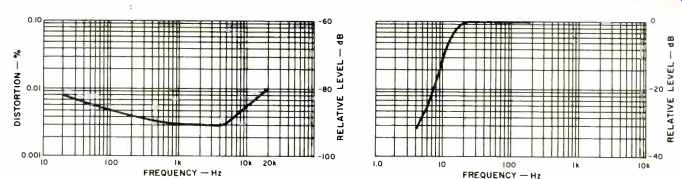
Fig. 2--Harmonic distortion vs. frequency at 2.0 V rated output.
Fig. 3--Response of the sub-sonic filter.
Harmonic distortion, for the high level inputs and with rated output delivered (2.0 volts), as a function of input signal frequency is plotted in Fig. 2. At mid-frequencies, THD was essentially that of the signal source, or around 0.003 percent. Highest observed THD occurred at 20 kHz and was 0.01 percent, well below the 0.04 percent limit published by Phase Linear. IM distortion measured a very insignificant 0.005 percent. Signal-to-noise measurements were made two ways. To achieve correlation between published specs and our measured results, we measured S/N using input and output references given by Phase Linear. Then, we also measured S/N for low and high level inputs in accordance with the new IHF Amplifier Measurement Standards, IHF-A-202. Using Phase Linear's measurement techniques, we read an S/N value of 93 dB for the high level inputs ("A" weighted), 90 dB for the MM phono inputs, and 81 dB for the MC phono inputs.
Repeating the measurements using IHF Standard input and output reference levels, high level S/N was 81 dB, phono S/N turned out to be 79 dB, and S/N for the higher gain MC inputs was 75 dB. As has been explained before, there is no direct way to calculate S/N results obtained using the new IHF method from those obtained using other S/N measurement and reference methods.
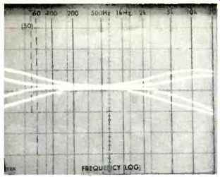
Fig. 4--Tone control range at each bass and treble turnover frequency. (Each
vertical division equals 10 dB.)
Fig. 5--Loudness control characteristics.
Input sensitivity for the phono inputs was 2.0 mV at the MM inputs and 0.24 mV at the MC inputs. These values can be translated to the new standard and become 0.5 mV for the MM inputs and 0.051 mV for the MC inputs. Phono overload in the MM inputs occurred with an input signal level of 130 mV at 1 kHz, while for the MC inputs it was 12 mV, exactly as claimed by Phase Linear. Maximum output before clipping measured 12.0 volts rms.
The built-in headphone amplifier delivered a maximum output of 240 milliwatts before clipping (into an 8-ohm load). At its rated output of 200 mW, THD at mid-frequencies measured 0.05 percent.
Frequency response was absolutely flat (via the high level inputs) from 20 Hz to 20 kHz and was down 0.4 dB at 30 kHz. RIAA equalization was also completely accurate from 30 Hz to 10 kHz, and was down 0.2 dB at 15 kHz. The response of the sub-sonic filter is plotted in Fig. 3, since its cut-off and slope are all below frequencies that can be swept and displayed on our spectrum analyzer's scope face. Figure 4 shows the composite range of control of the bass and treble tone controls (Phase Linear prefers to call them tone-contouring controls), and it will be noted that even when the "inboard" turnover frequencies are selected, there is very little change in amplitude of the important mid frequencies. This, to our way of thinking, is a much-preferred approach to tone control design than the more conventional central "hinge point" usually found at 1 kHz or thereabouts.
In keeping with current thinking about loudness compensation, Phase Linear elected to provide progressive bass boost only in their effective loudness compensation circuitry, as illustrated by the several sweeps (taken in 10 dB increments of the master volume control) shown in the 'scope photo of Fig. 5. It should be noted that while this loudness control arrangement does not provide the maximum flexibility that some preamps offer (those that have a separate loudness control and a separate volume control, or individual input level control adjustments), some additional flexibility is provided over and above that shown in Fig. 5, since it is possible to attenuate high-level input program sources by another fixed 20 dB (using the audio mute switch) for another set of loudness curves each further displaced by that amount of attenuation.
Listening and Use Tests
Aside from its very sophisticated switching circuitry, the Phase Linear 3000-II is a well designed, straightforward unit that offers a high degree of flexibility in use without adding needless embellishments that do little to improve sound quality. During listening tests, the preamp seemed particularly immune from any kind of overloading often caused by either steady-state or transient effects, whether amplitude, frequency, or slew-limit induced. There was a clarity and accuracy of sound reproduction that could not be faulted in any respect. Noise levels were inaudible, even when listening to soft passages of music via the MC phono input, and that includes power-line induced noise as well as random, wide band noise.
From its rugged cold-rolled steel chassis, to its gold-plated switch contacts, and its liberal use of 1 percent metal-film resistors, 2 percent poly capacitors, and solid tantalum capacitors, it is clear that the folks at Phase Linear were not about to compromise the design of this, their latest preamp, in any conceivable manner. We believe that their attention to detail and quality control, coupled with intelligent circuit design and human engineering, as represented in the Phase Linear 3000 Series Two, will pay off in terms of long-life and excellent sound reproduction for those readers who are fortunate enough to buy and own one.
--Leonard Feldman
(Audio magazine, Jan. 1979)
Also see:
Phase Linear Model 2000 Preamplifier (Equip. Profile, Sept. 1976)
Phase Linear 400 Amplifier (Feb. 1973)
= = = =