Manufacturer's Specifications:
Bandwidth: MM phono in to line out, 0.5 Hz to 250 kHz; MC phono in to line out, 1 Hz to 150 kHz; line in to line out, 0.1 Hz to 250 kHz.
RIAA Accuracy: ±0.1 dB.
Gain: MC pre-preamp section, selectable, 22, 25, 28, or 34 dB; RIAA amps, 39.4 dB at 1 kHz; dual-phase line amps, selectable, 14, 17, or 20 dB.
Input Characteristics: MM phono, selectable, 0 to 650 pF plus 47 kilohms; MC phono, selectable, 15 ohms to 47 kilohms; tuner, tape, and AUX, 100 kilohms.
Output Characteristics: 300 ohms, direct-coupled; tape output buffered.
Dimensions: 2.5 in. H x 19 in. W x 12.6 in. D (6.4 cm x 48.3 cm x 32 cm).
Weight: 12 lbs. (5.5 kg).
Price: $3,250 in platinum-gold anodized finish; $3,290 in black with metallic gray knobs.
Company Address: 828 7th Ave. S.E., Olympia, Wash. 98501.
------------
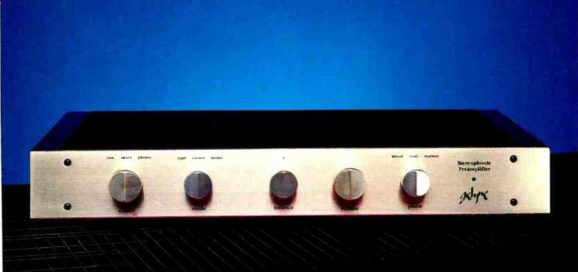
Klyne Audio Arts' SK-5 preamplifier has been in production since about 1984. The latest version, the SK-5A, is of the minimal-frills school, having no tone controls and a minimum of inputs and tape recorder connections.
The SK-5A's outputs are unusual. Each channel has two output jacks of opposite polarity which can be used together, as a balanced-line output, or individually. With this system, one can directly bridge-drive a stereo power amp for higher output power even if the amp lacks internal bridging circuits. This would involve feeding one of the amplifier's inputs from the preamp's normal output and the other amp input from the corresponding inverted output, and connecting the speaker between the two "hot" output terminals of the amplifier. (One such bridged amp would be needed to drive each speaker.) The SK-5A can also be used to drive the two channels of a regular stereo power amp in opposite phase (with one speaker wired out of phase) to reduce peak demands on the amp's power supply. This would involve using the normal output for one channel and the inverted output for the other channel. Using both the normal and inverted outputs for each channel, the SK-5A can also directly drive a stereo power amp that has differential (balanced) inputs. In many cases, balanced operation is such an amplifier's best-sounding mode. With any of these connections, the polarity of both the normal and inverted out puts can be easily by means of a front-panel "Phase" switch, to get the best sonic results from various program materials.
In all, this is an interesting and useful system that may well show up in future designs.
Physically, the unit is quite attractive, with a platinum-gold anodized front panel and knobs and black-stained oak side panels. A black/gray front panel is also available at a slightly higher price.
The chassis construction is straightforward and simple. It consists of a piece of metal bent to form the sides and front subpanel, a separate bolted-on back panel, and top and bottom covers. A large, double-sided p.c. board takes up the whole interior of the unit. This is one of the most attractive p.c. boards I've seen. The parts layout is beautiful, and I especially liked the Klyne dragonfly logo on the board. First class!
Front-panel controls, from left to right, include a three-position source selector switch, a combination tape-monitor/ mono switch (with mono mode available only in "Source" position), the balance and volume controls, and the afore mentioned "Phase" switch (which mutes the output when set to its center position). The muting circuitry also operates for 30 S when the unit is first turned on. (The power switch is on the rear panel, as Klyne feels the unit should be left on all the time.) A two-color LED to the right of the phase switch lights up in red when the unit is first turned on or when it is placed in mute mode, and turns green when the turn-on delay ends or muting is disabled.
On the rear panel are Tiffany phono jacks for signal input and output connections, a gold-plated ground post, a small power-on/off rocker switch, and an a.c. input assembly. This assembly includes a line filter, a power fuse, a voltage selector switch, and a three-pin male socket for the a.c. power cord.
Construction and parts quality of this unit are first-rate.
Circuit Description
The main amplifying blocks (the moving-coil pre-phono preamps, and amps) potted proprietary, and Klyne offers no information on their specific nature. However, I was able to examine block diagrams of the system interconnections and the buffer and power- supply circuitry.
The phono circuitry is quite flexible. Its input gain, input loading, and MC high-frequency roll-off are all selectable via two banks of DIP switches per channel. These switches, which also select MM or MC mode, are mounted on the p.c. board.
Loading is set via the rear switch banks. Input resistance can be set from 15 ohms to 1 kilohm in 11 steps; a 47-kilohm setting, the normal setting for MM cartridges, can also be achieved by opening all switches in these banks. Other resistances between 1 and 47 kilohms can be attained by plugging resistors of the correct value into sockets on the p.c. board. Input capacitance can be set from 110 to 650 pF in five steps or can be switched out altogether.
Selection of MM or MC mode is handled by the first two switches of each bank in each channel. The various MC gain settings are selected via the forward switch banks.
There are settings for 22, 25, 28, or 34 dB above the MM gain level. In MC mode, these switch banks also select first-order high-frequency roll-off to compensate for the rising high-frequency responses of many moving-coil cartridges. The-3 dB point of this roll-off can. be set from 12 to 50 kHz in 10 steps.

Fig. 1-Block diagram of signal path.
The moving-coil stages are powered by + 18 V regulators, one for each channel. The RIAA phono preamp modules have about 40 dB of gain at 1 kHz and are powered by two 18-V regulators, one positive and one negative, per channel. All inputs and outputs are protected by back-to back zener diode shunts. There is RC coupling between the moving-coil stage and the input of the RIAA stage, and between the RIAA stage's output and the selector switch.
As shown in Fig. 1, signals from the AUX, tuner, or phono inputs pass through the selector and monitor/mode switches to an FET buffer. This buffer circuit consists of a dual N-channel junction FET; one device is a source follower for the signal, while the other acts as a constant current source for the source follower. The source terminal of the follower goes through a resistor to the drain of the current source, with signal output being taken at this point. Since the signal input to the gate of the source follower is at 0 V d.c., the source will be at some positive voltage. The current source has a pot to set the bias or current level through both devices and, consequently, to adjust the voltage drop across the resistor between the source of the follower and the drain of the current source. This pot can be adjusted so that the signal output of the stage is 0 V d.c., eliminating the need for output coupling capacitors to the circuitry that follows. Similar buffer circuits are used for the tape outputs and for both the normal and inverted main outputs. All of the buffer circuits are powered by ±22 V d.c. provided by the separate positive and negative regulators which power each channel's output amplifiers.
The output of the main signal-path buffer goes through a series resistor to the volume and balance controls. Balance is accomplished by connecting the balance control elements as variable resistors to ground in series with resistors from the top of the volume control's elements. The advantage of this arrangement is that the signal does not pass through the nonlinear potentiometer contacts of the balance control elements; this results in potentially better sound and lower crosstalk. A possible disadvantage of this setup is that, as balance is shifted significantly off center, the buffer preceding the attenuated channel's balance control sees a lower load impedance, reducing ultimate input-signal over load capability.
Output of the volume control, which is a very nice laser-trimmed Alps unit, goes through a series resistor into the noninverting input of the line-amp module. A junction FET, connected from this input of the line amp to ground, functions as one of the muting elements controlled by the turn-on time delay and by the "Mute" position of the front-panel polarity switch. The two output phases of the line amp are capacitor-coupled to the inputs of the FET buffer circuits previously described. The outputs of these buffers are applied through a series resistor to a four-pole, double-throw relay (two poles per channel) and then to the normal and inverted signal output jacks. The front-panel phase switch controls power to this relay, which inverts the signal polarity at the output jacks. Provision is made on the p.c. board for capacitor coupling to the outputs, if desired. Two more junction FETs (one per signal phase) are connected on the output side of the series resistors to ground; they function as additional muting elements. Gain of the line amps is adjust able to several values lower than normal by installing sup plied resistors in sockets on the p.c. board.
The power-supply circuitry for the SK-5A is quite elaborate. A potted toroidal power transformer feeds a bridge rectifier, developing ± 36 V d.c. A pair of zeners across this unregulated d.c. line clamps the voltage. Presumably, this arrangement will blow the line fuse if the SK-5A is plugged into 240 V a.c. while its primary voltage switch is set to 120 V; another purpose would be to clamp transient voltage spikes coming through on dirty a.c. lines. A pair of three-terminal IC regulators reduces this unregulated d.c. to ±28 V. From this point, positive and negative regulators for each channel feed ±22 V d.c. to the line amps and FET buffers.
(These and all subsequent regulators are built from op-amp error amplifiers feeding Darlington pass transistors.) The 22 V line feeds positive and negative regulators for each channel to develop ± 18 V for the RIAA phono preamps. Each channel's +22 V supply also feeds the additional positive regulator that sends + 18 V to the MC pre-preamp stage.
The FET muting elements that precede the line amp and the output-polarity relay are powered by +36 V unregulated and -28 V regulated d.c.
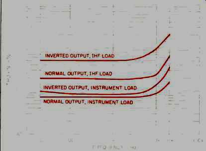
Fig. 2-THD + N for line section at 1-V rms output.
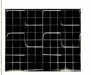
Fig.
3-Square-wave response through line section, with 20 kHz fed into instrument
load (top trace), 20 kHz fed into IHF load (middle), and 20 Hz fed into
instrument load (bottom). Scales: Vertical, 0.5 V/cm; horizontal, 10 µS/cm
for 20-kHz signals, 10 mS/cm for 20-Hz signal.
Table I--SMPTE-IM distortion vs. output voltage and loading for SK-5A's
normal and inverted outputs.
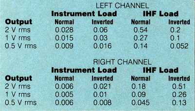
Table III--Phono overload vs. frequency at tape out (left channel).
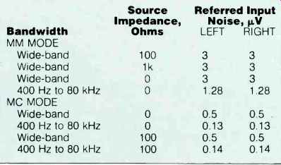
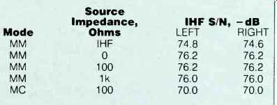
Table IV--Phono-section noise, referred to input.
Measurements
In a first quick look at the line section, I found a strange phenomenon. For output voltages above 2 to 3 V, the high-frequency responses above 2 or 3 kHz would drop slightly when the signal had been present for several seconds. This effect was more severe at higher output voltages. I contacted Klyne and found out that this behavior is normal for the unit and is caused by a biasing network that is signal-level dependent. The manufacturer assured me that this bias network is unbalanced only by sustained high-level signals such as those used in sine-wave testing, when the preamp is made to deliver more than about 3.5 V out, and that virtually no amplifier requires more than 3.0 V to drive it to full power. The bias imbalance, Klyne says, should not occur with music signals when output levels of 1 to 2 V are delivered to the amplifier. I then proceeded with my tests.
First, the line section gain was measured as a function of output loading and of the gain-reducing resistors supplied. With no resistors installed, the gain was 16.56 dB with an instrument load (91 kilohms in parallel with 250 pF) and 16.0 dB with the IHF load (10 kilohms in parallel with 1,000 pF).
With 51-kilohm resistors installed, gain with instrument and IHF loads was 14.2 and 13.6 dB, respectively. With 16.4 kilohm resistors installed, gain was 11.0 dB with an instrument load and 10.4 dB with an IHF load. Klyne, in the SK 5A's spec sheet, says the line amp gain is 20, 17, or 14 dB.
It turns out that the line amp modules themselves do have a maximum gain of 20 dB, but the gain from line input to line output is reduced to the measured figures by the losses occurring between the selector switch output and the line-amp module input.
Attempts to measure harmonic distortion above 2 to 3 V output were frustrated by THD that crept upward over time at frequencies above 2 or 3 kHz due to the aforementioned signal-dependent bias networks. THD + N was then measured at 1 V rms output; the results are plotted in Fig. 2. The dominant distortion components were low-order second and third harmonics. Of note here is the fact that the normal and inverted channel outputs don't have identical distortion and that the even harmonics don't balance out in the differential connection of the two outputs. To test for interaction between the normal and inverted output jacks when un equally loaded, one output was monitored while an IHF load was applied to and removed from the other jack. The measured output was not affected by the loading of the opposite-polarity output. This simply means that the output amplifiers for the two output phases within a line-amp module amplifier of my own design that has 845 triode tubes and develops 100 watts per channel.
A word about my current listening setup: Signal sources and preamps are placed along one wall of my living room. This equipment is connected to the power amplifiers by 30-foot lengths of Monster Cable Interlink Special cable, which has a capacitance of 1,500 pF per channel. The amplifiers are located near the speakers, which flank a corner fire place, and are connected to them by short cables.
I frequently connect tape recorders, CD players, or phono preamps directly to the 30-foot cables with no intervening preamps. When doing this, I adjust volume at the amplifier end using a dual 50-kilohm external control with 1-meter interconnect cables going to the power amps. The sonic effect of this particular external volume control is detectable but generally quite tolerable.
When I first received the SK-5A, I hooked it up and listened casually for a number of days. I reacted quite favorably to the way it sounded in my system, as did other listeners. Operation of all the controls was flawless, with no clicks, pops, or surprises.
A month or two after running test measurements on the unit, I set it up again in my listening room to find out more about its sonic performance. Record reproduction was musically very satisfying. Definition, detail, space, and harmonic structure were very good, with low irritation levels. I first had the phono section set to moving-magnet mode. (If a phono stage is reasonably quiet, its MM input mode will work with MC cartridges, like the Koetsu, which can deliver
0.5 mV at 5 cm/S.) Gain was just adequate and noise was noticeable (too much), but the sound was as described above. To my amazement, when I set the SK-5A to MC mode with 22 dB of added gain, the sound was substantially the same, though with lower noise, of course. This is the first time I have found the sound as good when going through a unit's MC pre-preamp as when going straight into the MM phono stage. The noise levels in the moving-coil mode were low enough for me-I could hear the noise near the speakers when the gain was set to normal playing levels and the arm was off the record, but it did not intrude when records were playing.
The sound of my tape players was good through the SK 5A's line section. However, when playing CDs through the line section, I found the sound a little less open, darker, and harder than when using the line section of the SP11 or going direct from the CD player (via the 30-foot interconnect cables) into the volume control at the power amps. I can't account for this, as none of the other sources sounded that way when going through the line section.
I really like this preamp, especially the way it enhances my enjoyment of the music on phonograph records. It's well worth a serious audition.
-Bascom H. King
(Source: Audio magazine, Jan. 1988)
Also see:
KM Labs SP-100 Preamp (May 1982)
Kinergetics KPA-1 Preamp (Equip. Profile; Aug. 1986)
Kensonic Accuphase C-200 Control Amplifier, P-300 Power Amp (Mar. 1975)
= = = =