SWISS NEUTRALITY
In the world of professional audio, engineers usually interconnect their equipment with balanced lines (cables), while audiophiles hook up their component systems with "single-ended," unbalanced, lines. Knowledgeable audiophiles have become aware of the advantages of using balanced interconnect lines. For the past few years, some high-end manufacturers have been marketing preamplifiers, power amplifiers, and other devices that they claim have balanced input and output stages. In the world of high end audio, equipment using balanced lines has acquired a certain cachet, but as might be expected, there is considerable misinformation and misunderstanding in respect to balanced audio circuitry.
Since the earliest days of hi-fi, audio components have been interconnected with single-ended, unbalanced, cables. These cables have a single conductor and a shield. The shield is connected to ground on the chassis of the component. While the shield can prevent electrostatic noise on the inner conductor, the shield itself carries audio signal currents. Thus, if the shield is near the magnetic field produced by the power line, 60-Hz hum will be induced in the shield and added to the audio signal. In the average audio component system, cable lengths are relatively short, and by routing the cables away from power lines, hum levels are fairly well attenuated.
In the professional audio fields of recording and broadcasting, the balanced line is the standard for interconnection of equipment. Audio professionals want absolutely pristine transmission of signals, and this means no hum, noise, or r.f. interference from emergency service vehicles, CB radios, fluorescent lights, or even radar sweeps! Essentially, a balanced cable uses two conductors for the audio signals, and both conductors are sheathed with a metal shield; neither of these conductors is connected to the shield.
Unlike the shield in an unbalanced cable, the balanced cable's shield does not ordinarily carry any audio current.
To help reduce magnetically induced hum, the conductors within the shield are also twisted together.
This twisting reverses the direction of the induced current, causing self-cancellation throughout the length of the cable.
In contrast to the often flimsy, unreliable RCA pin-type connectors in common use with unbalanced cables, balanced cables are terminated with the ubiquitous XLR three-pin connectors. These relatively massive connectors are very reliable, and by international agreement IEC 268-11, pin one is for ground (or shield), pin two is for positive (hot, signal), and pin three is for negative (return or common). Balanced cables with XLR connectors are rarely used with audiophile equipment. That's partially for reasons of expense, and partially because there's no technical advantage to a balanced line if it must connect to an unbalanced input or output at one end-and most audio components have only unbalanced connections.
However, some "balanced" outputs are not truly balanced with respect to ground. All that is done in such circuits is that an inverting stage (a circuit that inverts the signal's polarity by 180° and feeds it to the second signal line) is added. As two conductors and a shield are now used to transfer the signal, the audiophile thinks his system is balanced. But true balancing requires much more than just the presence of two signal lines! It is actually not so difficult to detect the more primitive balancing circuits.
One way to detect this is to look at the specs; if the output impedance of the unbalanced output is lower than that of the balanced one, it is likely that a simple polarity-inversion circuit is being used in the product. Such a product will also fail the "floating test": The output from one signal lead will decrease by 6 dB if you ground the other lead. If the output is not truly symmetrical or balanced, it will not have the same frequency and phase response, let alone interference rejection, as a truly balanced system.
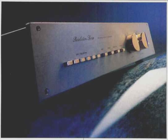
The foregoing remarks on balanced and unbalanced cables are a necessary preamble to this report on the Resolution Series FM 266 preamplifier from the Swiss company, FM Acoustics. This preamp has fully balanced inputs and outputs to match the company's 811 balanced-input power amplifier, which I reported on in the November and December 1990 issues.
The FM Acoustics 266 is an overwhelming component--from the sheer beauty of its high-tech appearance to the breakthrough technology of its design and circuitry. As with the 811 amplifier, the 266 is clearly in the realm of hi-fi fantasy and wish fulfillment as far as most audiophiles are concerned.
Needless to say, at $17,000 the 266 preamplifier will find far more sales appeal and appreciation in the professional audio fraternity.
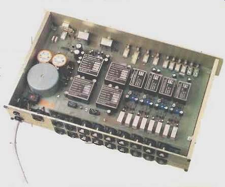
The FM 266 uses proprietary discrete Class-A circuitry with high-speed semiconductors. No overall feedback or feedforward is employed, and the circuitry is totally modular to help avoid obsolescence. The output level and balance potentiometers, specially made for FM Acoustics, are precision laser-trimmed. These controls use a new shielding technology, not just the usual metal case, to reject noise and interference and prevent them from entering the signal path. In addition, the level and balance controls are isolated from the gain stages by Class-A buffers. To take advantage of shorter paths from circuit elements to power supply, an on-board power supply is used, made possible by a proprietary transformer with double shielding. Many of the parts and components of the circuitry are individually matched and are of Mil-spec standard.
Of particular interest to phonophiles is the optional FM 222 phono module, which has an RIAA linearization circuit offering compensation for Neumann and Ortofon cutters, as well as the more usual selection of impedance and capacitance to match various cartridges. Ironically, in the twilight of the vinyl era, the sophisticated circuitry of the FM 222 (and FM 266) will permit true balanced input of moving-coil cartridges. All phono cartridges are, in principal, balanced. But when the usual RCA pin-terminated cables are used, they are transformed into an unbalanced configuration. FM Acoustics' CA25140 series of cables will provide a balanced interface for MC cartridges and the FM 222. For well-heeled, rock-ribbed, die-hard devotees of the LP, the FM 266, outfitted with the FM 222, is likely to be the component that affords the ultimate expression of vinyl LP reproduction.
I could fill pages with the many features of this extraordinary FM 266 balanced preamplifier, but among the more salient are six identical, balanced (symmetrical) high-level inputs and a balanced tape/accessories loop (also isolated by a Class-A buffer). These jacks have floating grounds and both inverting and noninverting connections, and the main output has a 180° polarity-inversion switch. Unbalanced (asymmetrical) signal lines are automatically converted to true symmetrical signals at the input of the FM 266; sensor circuitry automatically recognizes what type of connection is employed. The balanced output automatically compensates for differences between balanced and unbalanced loads. All outputs are short-circuit proof, and all input and output impedances are completely linear and identical over the full audio bandwidth. The balanced output can maintain absolute stability while driving any load through more than 500 feet of cable.
As a result, according to FM Acoustics, the FM 266 has an excellent common-mode rejection ratio of 100 dB over the full audio bandwidth, and it easily passes the "floating test" without causing any effect in the other signal carrying line. The FM 266 claims a whopping headroom of +20 dBv (7.75 V rms); I can easily believe it, with some of the great dynamic expression I've heard on certain CDs. Maximum output level is stated to be +28 dBv (18.5 V rms) into a 4.7-kilohm balanced load. Hum and noise are claimed to be 120 dB below full output from 20 Hz to 20 kHz. Rise- and fall-times are said to be a super-fast 0.3 µS! Bandwidth is said to cover 1 Hz to 2 MHz, with no more than 1° of phase shift from 20 Hz to 20 kHz. The rated output impedance is less than 10 ohms, and channel separation is said to be greater than 95 dB. Distortion at 1V over the full audio bandwidth is rated at 0.003%, with no higher order harmonics at all up to clipping level.
As always, even spectacular specifications are merely a guide to the sound of a component and its musical veracity. After extended listening with the FM 266, I was impressed in much the same way as I was by its companion FM 811 power amplifier, which is to say that its absolutely effortless dynamic music expression could take me from hushed string pianissimo to awesome fortissimo orchestral tuttis instantaneously. There was no lag or delay, no sense whatever of any kind of compression or limiting due to circuit inadequacies. The full gamut of orchestral dynamics was present with a verisimilitude equaled only by the live concert experience. You expect a truly clean signal from equipment of this caliber, but I was amazed at the low-level sounds or, when there were rests in the music, at the utter silence. The FM 266 was utterly and absolutely sonically transparent, with not even a vestigial hint of hum or a single noise artifact.
I've used balanced equipment for many years in my recording activities, and the stunning performance of the FM Acoustics 266 preamplifier made the case for a balanced system more convincing than ever.
(adapted from Audio magazine, Jan. 1992; Bert Whyte)
= = = =