
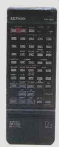
The C-383 preamplifier and M-383 power amplifier are at the top of Luxman's
current 300 series, a line of components more affordable than the Ultimate
series. (The Ultimate series has some intriguing pieces that I may want
to review in the future, e.g., the MA-88 mono tube power amp.) The models
in the 300 series have a built-in "Line Phase Sensor" that checks
whether the a.c. line plug is plugged in with the polarity that minimizes
leakage from the line to the chassis; minimizing leakage usually corresponds
to getting subtly better sound. These models also have a bidirectional system
bus, which al lows for more extensive control of interconnected Luxman components.
For example, if you press the "CD Synchro" button on the preamp,
and the matching CD player and cassette deck are in the system, the CD player
will stop at the end of the last song that can fit completely onto the tape
you are recording, so that the tape does not run out in mid-song. Multiroom
remote control is also available, provided you use optional accessories.
======
SPECS:
PREAMP:
Frequency Response: Phono (RIAA), 20 Hz to 20 kHz, +0,-3 dB; line, 10 Hz to 100 kHz, + 0.2,-0.8 dB.
THD: 0.003% for 2-V, 1-kHz signal at CD input.
S/N, IHF A-Weighted: MM phono, 91 dB; MC phono, 76 dB; line, 106 dB for 2-V input.
Input Sensitivity: MM phono, 2.5 mV; MC phono, 200 µV; line, 150 mV; video, 1 V, peak to peak.
Input Impedance: MM phono, 47 kilohms; MC phono, 100 ohms; line, 47 kilohms; video, 75 ohms.
Output Level: 1.0 V at pre-out jack.
Output Impedance: 20 ohms at pre-out jack.
Tone-Control Range: Bass, ±8 dB at 100 Hz; treble, ±8 dB at 10 kHz.
Loudness Compensation: +6 dB at 100 Hz, +4 dB at 10 kHz.
Dimensions: 17 1/2 in. W x 4 7/8 in. H x 14 1/2 in. D (43.8 cm x 12.5 cm x 36.3 cm).
Weight: 15 lbs. (7 kg).
Price: $1,200.
AMP:
Power Output, 8-Ohm Loads:
Continuous (rms), 200 watts per channel, 20 Hz to 20 kHz, at 0.04% THD; dynamic, 300 watts per channel; bridged mono, 700 watts at clipping.
Frequency Response: 10 Hz to 100 kHz, +0,-1 dB.
S/N, IHF A-Weighted: 126 dB.
THD: 0.008% at 1 kHz for 200 watts into 8 ohms.
Input Sensitivity: 1V.
Input Impedance: 45 kilohms.
Dimensions: 17 1/2 in. W x 7 in. H x 16 7/8 in. D (43.8 cm x 17.8 cm x 43.1 cm).
Weight: 39 lbs. (17.7 kg).
Price: $2,000.
Company Address: 915 Washington Ave. South, Minneapolis, Minn. 55415.
======
Circuit Description
In Luxman's literature, the C-383 pre-amp is said to minimize the length of the audio signal path by keeping the audio circuits away from the front panel and using long shafts from the front-panel controls to the actual switches and potentiometers.
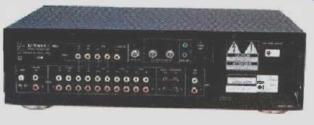
The motorized volume control is said to be superior to active signal attenuators. Separate windings on the power transformer isolate the analog power supply and audio signal circuitry from the digital supply that powers the control microprocessor. This preamp also has video switching, with high-grade video buffers for each input, and allows for two audio/video inputs, a VCR input and output, and a TV monitor output.
I am just going to touch on what I consider the significant highlights of this preamp's extensive circuitry. All the audio gain blocks are implemented with IC op-amps. Input-signal and tape-monitor selection are accomplished with solid-state analog-switch ICs, whereas the switching after signal selection is done with a combination of actual switches and relays. In the normal operating mode, the selected signal passes through the stereo/mono switch, the "Balance" control, and a unity-gain noninverting buffer and then out to the "Signal Processor" output jacks. Coming back in, via the "Signal Processor" input jacks (normally connected to the processor-out jacks by jumpers), the signal continues on its way through the tone-control amplifier, the -20 dB attenuator, volume and loudness-compensation circuits, and finally through the line-amplifier gain block and the main output jacks. (Whew! I'm not so sure about Luxman's minimizing of the signal path!) In the "Line Straight" mode, simplicity fares somewhat better: The selected signal is routed to the-20 dB attenuator and continues to the main out jacks via only the "Volume Control," "Loudness" switch, and output amplifier.
The control microprocessor and associated digital control circuits are on a p.c. board behind the front panel. It is protected from the audio circuitry on the main p.c. board by a metal shield on the back side of the control board. This is a good and sensible way to isolate the digital control circuitry.
The M-383 power amp uses "All-Stage Symmetrical Push-Pull" circuitry (translation: complementary symmetry), along with a "Duo-Beta" topology that permits low amounts of overall negative feedback along with good d.c.-off set stability. Star power distribution (independent supply lines to each circuit), independent left and right "Input Level" controls and "Clipping Indicator" LEDs, two speaker-selector but tons, and a remote power on/off facility round out the features of the power amp.
Circuitry in the M-383 is mostly composed of discrete bipolar devices. The in put stage, which I deduce is a complementary differential amplifier, is in the form of an IC containing either bipolar or junction FET transistors. The rest of the circuitry is of the familiar complementary topology, consisting of a last voltage amplifier driving a triple Darlington-connected, emitter-follower output stage utilizing three
pairs of output devices per channel. Each channel is powered by its own rectifier bridge and filter capacitors but fed from one common secondary winding on the power transformer.
The novel optimum a.c. line-polarity detector is simplicity itself. What is set as the low side of the unit's a.c. internal wiring goes through a high-value resistor (4.7 megohms) in series with a neon bulb to a touch plate on the back panel. When you touch this plate, your capacitance to ground apparently causes enough current to flow to light the bulb. If this is the case, you reverse the polarity of the a.c. line plug in the socket. This would be especially simple if each a.c. line plug had equal-width blades; the C-383's plug does, but the M 383's does not. What's a person to do? You could either trim the wide tab on the neutral blade of the plug with some heavy duty wire cutters or use a three-wire to two-wire adaptor and cut off the excess width of its neutral blade. Luxman, however, points out that it's safer in the long run to rewire the a.c. outlet.
Construction and build quality of these pieces is typical of Japanese equipment in this price range, with rather thin-gauge sheet metal, reasonable parts quality, and adequate-if not elegant-quality wiring and construction.
Measurements
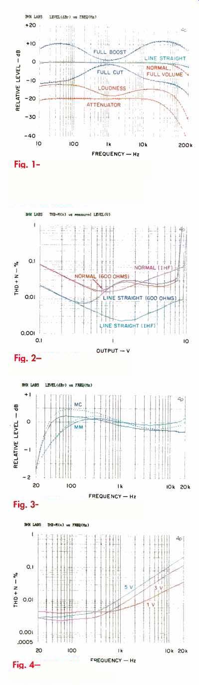
Fig. 1--Frequency responses, tone-control range, and loudness compensation
of C-383 preamp.
Fig. 2--THD + N vs. output, C-383 preamp.
Fig. 3--RIAA equalization error.
Fig. 4--THD + N vs. frequency, MM phono.
Gains and IHF sensitivities for the various input and output combinations of the Luxman C-383 preamplifier are enumerated in Tables IA and IB.
A series of frequency responses (not shown) were taken of both channels with the preamp in its normal mode. As is typical for most preamps, the high-frequency response was most extended when the "Volume Control" was at maximum (with a 3-dB down point of about 125 kHz) and least extended with volume down about 6 dB from maximum (where the response was 3 dB down at about 67 kHz). With volume down about 40 dB, the high-frequency response approached that with volume at maximum. In the "Line Straight" mode, the preamp's high-frequency bandwidth (-3 dB point) was greater than in the normal mode. Rise- and fall times with volume at maximum and at an output level of ±5 V were 2.8 uS and 1.5 µS, respectively, for normal and "Line Straight" modes. With the volume control a t-6 dB, these rise-times lengthened to 5.5 and 5.0 uS, respectively.
Frequency responses for various conditions are shown in Fig. 1 for both channels. One pair of curves shows the effects of the tone controls in normal mode; other curves show the differences in response for the normal and "Line Straight" modes with the tone controls set flat. The "Attenuator" curve, at-20 dB, is for volume at maximum in normal mode with the "Attenuator" button engaged. Finally, the remaining curve is the result of pushing in the "Loudness" button when volume is set at-20 dB. Square-wave responses (not shown) all displayed the effects of, and correlate with, the various frequency responses discussed above. A 20-Hz square wave showed considerable tilt in the normal mode and none in the "Line Straight" mode.
Figure 2 plots distortion at 20 kHz as a function of output voltage, for normal and "Line Straight" modes, instrument/IHF loads (whose effects were essentially the same), and 600-ohm loads. Results are shown for the right channel only, as distortion there was slightly higher than for the left channel. Distortion and noise were somewhat lower in the "Line Straight" mode than with the normal loads (instrument/IHF), and performance into 600 ohm loads was very similar in both modes for output voltages above about 1 V. Measured distortion performance of this unit is quite good, and the C-383 appears to drive a 600-ohm load handily.
Interchannel crosstalk (not shown) with volume at maximum was generally better than 90 dB down at frequencies from 400 Hz to 2 kHz, depending on condition, and rose at 6 dB per octave, in either normal or "Line Straight" mode. End amounts at 20 kHz ranged from about -70 to -58 dB, de pending on direction and mode. With the "Volume Control" set to about 20 dB of attenuation (typical of moderate to loud volume settings in a working system), crosstalk increased to some -64 dB at 1 kHz, rising to -40 dB at 20 kHz.
Input resistance for line inputs was 48 kilohms with the "Rec Out Selector" off and 41 kilohms with it set to the selected input. Output resistance was a low 12 ohms in either normal or "Line Straight" mode.
Table 1A--Gain levels for C-383 preamplifier.
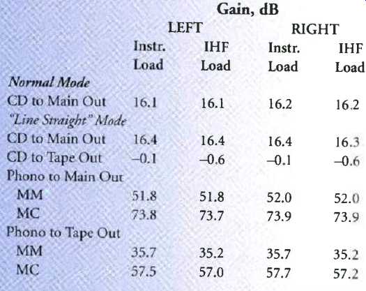
Table IB--Input sensitivities for C-383 preamplifier, with IHF loading.
Table II--Output noise levels of C-383 preamplifier's line amp section for counterclockwise (CCW), worst-case (WC, typically -6 dB), and full clockwise (CW) settings of "Volume Control." IHF S/N figures for left and right channels are 89.2 and 89.8 dB, respectively, in normal mode and are 89.7 and 89.4 dB, respectively, in "Line Straight" mode.
The two channels of the "Volume Control" tracked each other within ±0.1 dB from 0 to 33 dB of attenuation, diverging to a difference of about 1.2 dB at the-58 dB setting and 4.5 dB at -75 dB.
Line-amplifier output noise is listed in Table II for normal and "Line Straight" modes; "worst-case" refers to the setting where the noise was highest, usually corresponding to the volume setting 6 dB down from maximum. Noise levels with the worst-case and clockwise volume settings are lower in the "Line Straight" mode. This is because the normal mode puts the tone-control amplifier between the source and the "Volume Control," thereby adding its noise with the volume up but having no effect with the volume down.
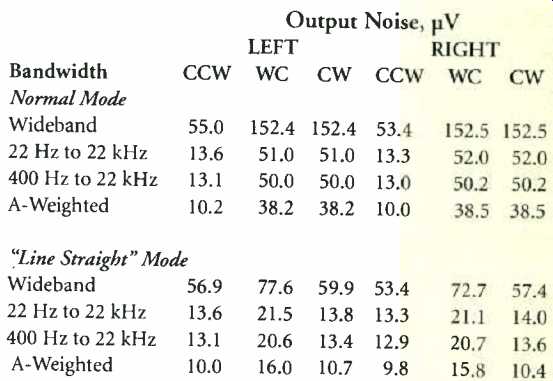
Figure 3 shows RIAA equalization error for the phono preamp's MM and MC modes. Data is shown for instrument loading; IHF loading dropped the levels about 0.5 dB but didn't alter the curve shapes.
There is a considerable difference in the two modes' equalization error below 200 Hz that I can't account for in the circuitry.
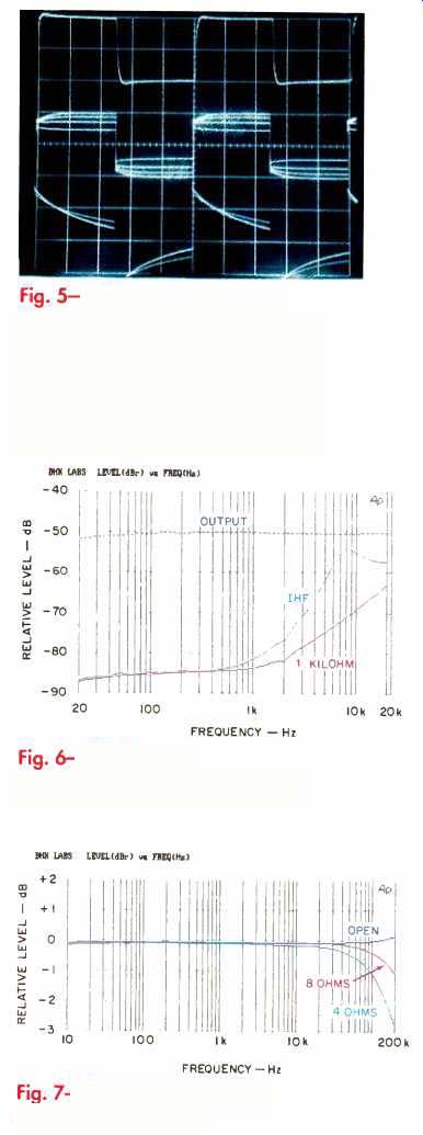
Fig. 5--Square-wave response, MM phono, for 10 kHz (top), 1 kHz at varying
drive levels (middle), and 40 Hz with instrument and IHF loads (bottom).
Fig. 6--MM phono response and crosstalk.
Fig. 7--Frequency response of M-383 amp.
The low-frequency roll-off was probably intentional, to help re duce spurious subsonic energy.
Personally, I prefer a design that has flat low-frequency equalization response, with an option to apply a subsonic filter (if need be) for a particularly warped record.
Total harmonic distortion in the MM mode for the left channel is plotted in Fig. 4 for output levels of 1, 3, and 5 V rms for instrument loading. Distortion can be seen to rise at high frequencies. Usually, distortion in a feedback equalizer is lower at high frequencies, where there is more loop gain. In this circuit, what appears to be heavy high-frequency open-loop roll-off compensation (as judged from the phono equalizer's schematic) seems to result in reduced loop gain at high frequencies, which would account for the rise in distortion with frequency. The IHF load didn't materially affect 20k the distortion results shown. In the MC mode, the distortion at 5 V output was about the same as that in Fig. 4 above some 2 kHz; it was limited by measurement-system noise below about 700 to 800 Hz.
In measuring phono overload versus frequency, using a pre-equalized sine-wave source, I ran into some difficulty at high frequencies. For this test, my Audio Precision System One's generator produces the RIAA pre-equalized signal and regulates its amplitude to produce a constant measured 3% THD at each test frequency;
the resultant input and output voltage from the phono preamp under test is then measured. If the preamp handles all frequencies equally, the attainable output should be flat with frequency, and the in put voltage which produces that constant output will be the inverse of the RIAA equalization curve. When the C-383's phono preamp was pushed to clipping, high-frequency instability (in the range from 10 to 20 kHz) manifested itself as a low-frequency oscillation that prevented the Audio Precision detector from settling down for a legitimate reading. What I was able to get was an essentially constant 10 V rms, with either instrument or IHF loading, from about 30 Hz to 10 kHz in both MM and MC modes. Since the input acceptance at 1 kHz is about 170 mV in MM mode and some 28 mV in MC mode, it is exceedingly unlikely that the C-383's phono equalizer would be overloaded by any normal or even high-output phono cartridge.
'Scope waveforms of MM phono response to square waves are shown in Fig. 5. The top trace is for 10 kHz with instrument loading; vertical sensitivity is 0.5 V/division. With IHF loading, output dropped slightly and rise-time increased from 1.8 to 2.6 µS. The middle trace, for ,1 kHz and trace sensitivity of 1 V/division, shows the high-frequency compression that takes place as the output is driven to levels above about 1 V, peak to peak. The compression behavior was reasonably symmetrical, which is desirable. The bottom trace is for 40 Hz, with instrument and IHF loading; the IHF load produces the greater tilt. In the MC mode, high-frequency compression was much less, allowing the C-383 to deliver more than twice the output it did in the MM mode before compression became visible. However, rise-time was somewhat slower, at about 5 µS. Also, the 1-kHz square wave is flatter, without the overshoot at lower levels visible in the middle trace of Fig. 5.
Phono interchannel crosstalk is plotted in Fig. 6 for the MM mode. One solid curve shows crosstalk with the input of the undriven, measured channel terminated with a 1-kilohm load; the other solid curve shows the results with the IHF moving magnet source as a termination. Results were about the same in both directions. In the MC mode, the crosstalk was a flat -65 dB in both directions with a 100-ohm termination resistor but, strangely, was quite a bit lower at mid-frequencies when the un driven channel was not terminated.
Phono referred input noise, along with IHF S/N ratios for the whole preamplifier in both phono modes, are given in Table III for different source impedances and bandwidths.
I didn't test the preamp's video switching, external remote sensor, or remote control "Bus Line" functions.
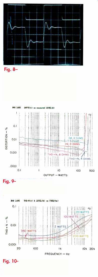
Fig. 8--Amp square-wave response for 10 kHz into 8-ohm load (top), 10 kHz
into 8 ohms paralleled by 2 µF (middle), and 40 Hz into 8 ohms (bottom).
Fig. 9--Amp THD + N at 1 kHz and SMPTE IM vs. power.
Fig. 10--Amp THD + N vs. frequency with 4-ohm loads.
Voltage gains and sensitivities for the M-383 power amplifier were 28.9 and 28.8 dB for the left and right channels, respectively, with corresponding IHF sensitivities of 101.3 and 102.3 mV. Gain was about 6 dB higher than the usual 26 dB.
Frequency response as a function of load is plotted in Fig. 7. As can be seen, high-frequency band width relates strongly to resistive loading. Response with speaker systems having moving-coil tweeters, but lacking impedance-compensating networks that keep high-frequency impedance down, will likely look more like the curve for open-circuit loading. The open-circuit response appears to be peaking at a frequency above the 200-kHz limit of the plot.
Figure 8 shows square-wave responses. In the top trace, for 10 kHz into an 8-ohm load, every thing looks good and well behaved; rise- and fall-times are 500 about 1 µS. With a paralleled 2-µF capacitor (middle trace), there is ringing behavior typical of most transistor amplifiers. In the 40-Hz trace (bottom), the tilt is very slight, indicating extended infra sonic response.
Figure 9 shows SMPTE-IM distortion and 1-kHz THD + N, as a function of power output, with 4- and 8-ohm loading for the left channel. Figure 10 shows THD + N as a function of frequency, for 0k 20k various power levels into 4-ohm loads. A spectrum of harmonic distortion for a 1-kHz signal at 10 watts output into 8 ohms (not shown) revealed mostly even-order distortion, with a descending envelope of harmonic amplitude versus harmonic number. Typically, when the dominant harmonics are even, the amount of total harmonic distortion versus power output at a particular frequency is relatively constant at all power levels up to clip ping; this is shown in Fig. 10 to be more or less the case.
Damping factor at 100 Hz was 247 and 234 for the right and left channels, respectively. As with many power amplifiers, damping factor started to decrease at 300 to 400 Hz and reached a final value of about 29 at 20 kHz.
This amp's interchannel crosstalk was higher in the right-to-left direction.
Crosstalk increased over most of the audio range at 6 dB/octave, indicating capacitive coupling between the channels. The amount was about-97 dB at 1 kHz, in creasing to about -73 dB at 20 kHz. Crosstalk in the left-to-right direction was some 12 to 13 dB better.
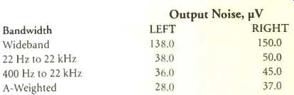
Output noise levels, along with IHF S/N ratios, are given in Table IV. The noise level is very low, and no sign of the line-harmonic background that I saw in the distortion-spectrum plot shows up here.
Dynamic power measurements with 8-ohm loads yielded an equivalent output of 306 watts at the beginning of the 20-mS burst period and 289 watts at the end of the burst. For 4-ohm loads, the results were 578 and 512 watts, respectively. Based on the higher power at the beginning of the burst, IHF dynamic headroom computes out to 1.85 and 2.18 dB for 8- and 4-ohm loads, respectively. Continuous maximum power output at the visual onset of clip ping was 225 and 324 watts, respectively, for 8- and 4-ohm loads.
The a.c. line draw was 360 mA. This indicates a relatively low output-stage idling current.
Table III--Phono referred input noise for C-383 preamplifier with short-circuited and loaded inputs. Loading was 100 ohms in MC mode and IHF simulated moving-magnet load in MM mode. IHF S/N ratios for either channel, with inputs loaded as above, are 75.0 dB in MC mode and 78.0 dB in MM mode.
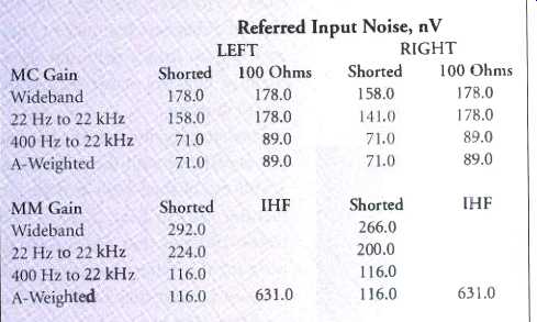
Table IV--Output noise levels for M-383 power amplifier. IHF S/N ratios are 100.0 and 97.7 dB, respectively, for the left and right channels.
Use and Listening Tests
Digital signal sources used in my reference system during the review period included Counterpoint DA-11A and PS Audio Lambda CD Drive transports feeding Sonic Frontiers SFD-2 and other (experimental) D/A converters. For analog sources, I used an Oracle Audio turntable fitted with a Well Tempered Lab tone-arm and a Spectral Audio MCR-1 Select moving-coil pickup, feeding a Vendetta Research SCP-2C phono preamp. I also used Nakamichi's ST-7 FM tuner and 250 cassette recorder and a Technics open-reel recorder. Other preamplifiers used included a unit from Quicksilver Audio, a Forssell tube line driver, and a First Sound Reference II. Other power amplifiers on hand were a Crown Macro Reference, Quicksilver M-135s, and an Arnoux MB300A switching design. Loudspeakers used were B & W 801 Matrix Series 3s, augmented in the range from 20 to 50 Hz by a pair of experimental subwoofer systems, each using a JBL 1400Nd driver in a 5-cubic-foot ported enclosure.
When I first received the Luxman equipment, I tried out the M-383 power amplifier in my system. My listening notes indicate that it sounded quite good but was a little dull and closed in compared to my highest resolution amplifiers. On the other hand, it didn't sound edgy or irritating.
After measuring the Luxman units, I connected up both the preamp and the power amp in my system and just started listening to different signal sources. I must admit I had a predisposition to think that the sonic qualities of this pair wouldn't be in the same league as that of some of the reference equipment I normally use. Well, I was pleasantly surprised and found, much to my delight, that music issued forth in a very listenable manner. I found myself saying "Boy, that sounds good" more than a few times. Imaging and spatial properties were quite good, with tonal balance generally like the balance I am used to with my reference equipment.
Edginess and irritation levels, an aspect of reproduction to which I am hyper sensitive, were acceptably low. A good sign was that, as I listened to various types of music, I didn't have an itch to get back to "the good stuff." Operationally, everything worked with out any bothersome problems. Once, when I was listening to phono, the preamp muted when I switched on my subwoofer amp.
Although the manual indicates one just has to touch the a.c. line-polarity detector's plate to operate it, I found that I had to ground the plate with a wire or clip-lead to a grounded piece of equipment in order for the indicator to light when the polarity was wrong. Although I didn't regularly use most of the remote's many features, I particularly liked having remote control of signal source, volume, and muting. I do wish that the remote had a balance function, as that really enables one to completely dial in a particular recording from the listening position.
In summary, I find the Luxman C-383 and M-383 to be musically satisfying, and I urge prospective buyers of separates in this price range to give them a listen.
-Bascom H. King
(Source: Audio magazine, Jan. 1995)
Also see:
Luxman LV-109 Integrated Amplifier (Equip. Profile, Sept. 1987)
Luxman DX-103 Compact Disc Player (Nov. 1984)
Lux Audio MB-3045 Power Amplifier (Nov. 1977)
= = = =