More Selective TV Sets
Q. My color TV set is being fed by a rotating, high-gain, highly directional antenna, 66 feet above the ground.
Distant stations are often adversely affected by adjacent-channel interference caused by strong local stations.
Why are not Tv set makers able to eliminate this adjacent-channel interference?
Great strides have been made in this respect where the FM band is concerned. Crystal filters, such as are used in Heath and other tuners, allow one to listen to a weak station even when it is next to a strong local one. It is possible to apply similar circuits to a Tv tuner so as to accomplish similar results for the video and audio performances of TV sets? If so, why are not the manufacturers making use of these filters?
- Chester J. Alkema, Grand Rapids, Mich.
A. There is no technical reason why television receivers cannot be made more selective, and, at the same time, produce pictures with even more definition than is presently the case.
However, economic considerations play a role here. Because competition among manufacturers is keen and costs are measured in tenths of a cent, a manufacturer would have to be pretty sure that these circuit changes would really be important to the consumer before he would decide to include them.
As it is, you are one of the very few who is interested in having such a set. Hence, you will either have to do some design work of your own or simply enjoy your present set.
Another problem regarding selectivity is one which involves the front end. Very often, amateur radio operators are blamed for creating interference to television receivers. True, the emanations of some of these transmitters do find their way into television sets, but it is not the fault of the operator of the station. It is the fault of poor front-end design of the television receiver which allows this type of interference to enter the receiver.
This is the kind of problem that most television users would not understand as a design problem, and, therefore, would not complain to the manufacturers of the sets.
Q. I want to learn how to construct a voltage divider to put between my cartridge and preamplifier in order to cut down first-stage overload.
-R. B. Taylor, Sellersville, Pa.
A. You can make a voltage divider which will reduce the output from your cartridge sufficiently to prevent overloading of the early stages of your equipment.
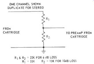
There are two resistors needed. Their total ohmic value, when they are connected in series, is 47 k ohms so that it will match the cartridge's requirements. You probably will need to reduce the signal output to perhaps 6 dB below its present level. Therefore the value of each resistor should be 23.5 k ohms. However, there is no such value made in standard resistance sizes. Therefore, 22 k ohms is the closest obtainable value. (There will be no degradation of sound quality as a result of this slight discrepancy.) See Fig. 1.
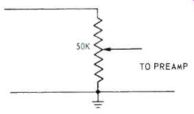
Fig.1--If the signal level is still too high, change the resistances to
33 k and 15 k ohms. The 15 k resistor should he placed closest to ground
because it is the one which must develop the lower voltage.
Place the two voltage dividers (one for each channel) in a metal container.
Mount the input and output connectors to the box. This arrangement is useful in eliminating unshielded resistors and their leads.
It might be convenient to have a method whereby any voltage between zero and the full output capability of your cartridge can be fed to the input of your preamplifier. This can be accomplished through the use of a 50-k ohm potentiometer. See Fig. 2.
The 50-k ohm resistance value of this pot is close enough to the recommended 47-k ohm cartridge termination that there will be no degradation of sound quality.
As with the circuit of Fig. 1, this potentiometer should be mounted in a metal box.
If you have a VTVM and a test record, the two potentiometers needed for stereo should be adjusted to provide equal voltages between their wipers and ground.
Regardless of which of the two circuits you choose, connect a ground wire between the metal box in which the circuit is mounted and your preamplifier.
Background Music
Q. What is meant by "background music"?
-Mr. M. Reich, Bronx, N.Y.
A. Background is that music which you often hear in restaurants, banks and other establishments. It is carried on ordinary FM stations, probably the very ones to which you listen all the time. You cannot hear it at home, however, because it is transmitted on what is known as a subcarrier. The main FM carrier is modulated by the audio you hear, plus some stereo information which you cannot hear on a monophonic receiver. Furthermore, there is a 67-kHz carrier which also frequency modulates the main carrier.
This carrier, in turn, is frequency modulated, and contains the background music service.
In order to receive this background music programming, the FM signal is first detected in the usual way. The regular program is then filtered out of the resulting audio and all that is left is the recovered 67-kHz subcarrier. This carrier is then passed into circuitry which detects its FM just as is done when detecting the FM with which you are familiar.
Transformers in Solid-State Amplifiers
Q. It appears that most, if not all, of the latest solid-state amplifiers have no output transformers, driver, or inter stage transformers.
Do you feel there is any advantage in performance of either having driver transformers or not having them? Would their presence deteriorate transient responses?
- Leonard Drasin, Jamaica, N.Y.
A. I do not think driver transformers impede good transient response. They are not required to handle much power. Further, because of the low impedances associated with solid-state circuitry, these transformers will not have sufficient turns to cause severe losses of highs because of distributed capacitance.
The use of driver transformers solves some design problems, especially that of phase splitting.
Meter Disagreement
Q. Several FM stereo tuners I have seen have both a center-of-channel tuning meter and a signal-strength meter. If properly aligned, should the two meters agree with one another as to the point of best tuning? If not, which one should be relied on?
- Leonard Drasin, Jamaica, N. Y.
A. Theoretically, center channel meters both should give proper readings at the same time. In other words, when the center-of-channel meter shows proper tuning, this reading should coincide with the maximum signal point on the signal strength meter. I noticed, however, that in many cases the readings will correspond at one particular signal strength -- that used when aligning the tuner.
A signal which is stronger or weaker than this one will produce disagreement between the meter readings.
I am not altogether sure of the reason why this discrepancy should exist.
My personal guess would be that it has something to do with current flowing in the detector circuit and the changes in diode conductivity with varying signal levels feeding this circuit.
In any case, when the two meters disagree, rely on the center-of-channel meter reading.
Of course, if the readings are in violent disagreement, it might indicate that you must have your tuner aligned.
Relay Protection for Solid-State Amps
Q. Why don't manufacturers use relays as aids in protecting solid-state circuits from overload?
-Name withheld.
A. When transistor circuits are overloaded, they often burn out with lightning speed. Therefore, in order to protect such devices, the protective circuit must sense the potential danger even faster than it can act to cause the damage.
Being mechanical devices, relays are not fast acting. Therein lies the basic reason why they are not used in solid-state amplifier protective circuits. Further, relays are not completely reliable in other ways. Oxidation of their contacts can make them useless. Failure of a restoring spring can also destroy their usefulness.
==========
Letters to the Editor
Center Channel
Mr. Bert Whyte's timely "Special Report On Four Channel Sound" inspires a few comments:
In reference to center "ghost" or "phantom" channels, he states that ... a phantom middle channel simply is nowhere near as realistic as the actual third channel." I heartily agree! Although this type of center fill does indeed reduce (or eliminate) the hole in the middle," it obviously reduces (or eliminates) a stereo dimension which can no longer be heard in recent recordings. This effect, which was evident in some older 2 mike, 2 channel recordings, provided a depth and "behind the speakers" transparency which was startling, but was difficult to maintain. It has been my experience that a true, separate, front-center channel not only fills the "hole," but provides this dimensional effect reliably. In spite of this, the industry, with two more channels at their disposal, choose to ignore "stage center," and assign the extra channels to the rear. Other members at TEAC Corporation of America and myself, have been experimenting with all conceivable 4 channel geometry, and conclude that the front-center addition should take priority. Mr. Whyte seems to imply a similar attitude in his reflections of his past experiences.
I should like to point out an error in the same article: The TEAC 4 channel-in-line record-play deck (Model 4010SRA), sells for $799.50, not $1,200.00 as reported.
Sincerely,
TEAC CORPORATION OF AMERICA, Arne Berg, Director of Audio Products
Highly controversial-but readers' comments would be welcome. -Ed.
Outdoor Speakers
I am planning to install a stereo system in my Palm Springs, California home and would like to put two speakers in the garden and leave them there for months at a time. Because of the wide range of temperatures on the desert and the possibility of rain, such speakers would have to withstand severe climatic conditions. Would you be able to direct me to a company or companies who would have such a speaker able to withstand these conditions and still give excellent fidelity?
SEYMOUR OPPENHEIMER, Chicago, Ill.
Quite a number of companies make good outdoor speakers, Bozak, JBL, Electro-Voice and Jensen come to mind. The Bozak model 1000 is housed in a hemispherical steel enclosure and costs about $80 while the JBL "Carnival" is contemporary in styling at just over $100. Two other possibles are the Electro-Voice "Musi caster IA" and the Jensen HF-100Aboth horn loading units costing around
$70. All of these speakers will give very good results and are immune from the effects of the weather--except hurricanes!
Adding a Bass Speaker
I would like to add Wharfedale 12 inch bass speakers to my Quad electrostatics. What crossover do I need? Can I use an electronic crossover?
-JOHN RUSSELL, New Canaan, Conn.
You will find full details of such a system in the next issue (March) complete with electronic crossover which is probably more flexible for this purpose than conventional types.
Acoustic Matrixing
Has Audio published any articles on stereo speaker matrixing as used by Jensen?
-PETER WESTBROOK, St. Charles, Ill.
Yes-as far back as November, 1960.
The article was entitled "Acoustic Matrixing, a basis for new loudspeaker developments" and it was written by Norman Crowhurst. Another article appeared in the issue for October 1969 and this one was called "Single Speaker stereo" by C. G. McProud.
==========
==========
Advertisements section below:
Where do you put Scott Quadrant Speakers?
Anywhere!
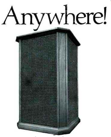
Speaker placement used to be extremely critical if you wanted to get the optimum stereo effect. But not any more. With Scott's new Quadrant Q-100 Speaker*, you can forget about placement problems. Quadrant speakers have been specifically designed to eliminate the "hole in-the-middle" effect that plagues conventional speakers' stereo performance.
Quadrant speakers have been used, with sensational results, in actual press demonstrations of 4-channel stereo, where the use of conventional speakers results in multiple "holes-in-the-middle." Here's how the Quadrant idea works: two woofers radiating more than 180° each and four midrange/ tweeters radiating more than 90° each are placed around the four sides of the Quadrant speaker. They project full-frequency sound in a complete circle.
The sound is radiated both directly at you and in all directions, using the reflective qualities of your walls to heighten the live stereo effect. Your entire living room becomes a giant sound chamber. No matter where your Quadrant speakers are, you can go anywhere in the room and be surrounded by rich, full range stereo sound! This freedom of placement is particularly important if you're planning ahead toward 4-channel stereo with its four separate speaker systems.
Hear for yourself the dramatic difference between Scott Quadrant stereo and conventional speaker i stereo. Your Scott dealer will show you that no matter where you place your speakers, or what *. shape your room, the Quadrant will deliver * hole-free wall-to-wall stereo. $149.95 each.
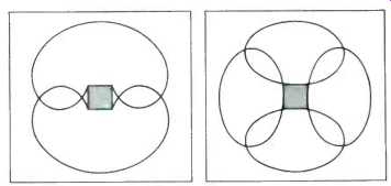
----Two woofers are mounted on opposite sides of the speaker enclosure, each radiating low frequency sound of more than 180°.
---Four midrange/tweeters are mounted one to a side, each projecting high frequency sound waves in an arc of more than 90'.
H-H SCOTT
H. H. Scott, Inc., Dept. 000-00, Maynard, Mass. 01754
Export: Scott International, Maynard, Mass. 01754
---------------------
TANDBERG
NEW 6000X STEREO DECK
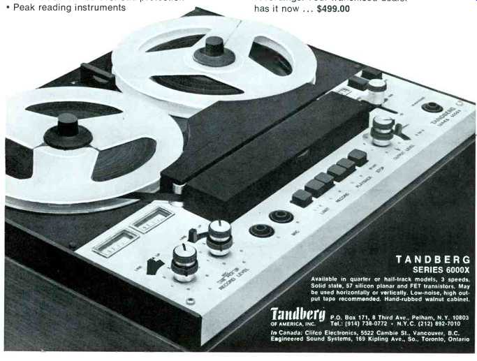
A Dynamic New Thrust In Recording Capability Featuring Our Unique CROSSFIELD Design
The 6000X challenges the most precise professional instruments that sell for $1,100 or more. At 3 3/4 ips, this new stereo deck surpasses the 7 1/2 ips performance of our world famous, top rated Model 64! It offers the truest high fidelity you've ever heard, even at 3 3/4 ips (40-18,000Hz 12 1/2 db). And, it incorporates a completely new design for the 70's...fresh, interesting -- inviting use!
Convince yourself. Would you believe... Signal-to-noise ratio at 62db 70db dynamic range, plus An additional 24db overload protection Peak reading instruments. And would you believe...
4 hyperbolic, mumetal screened, precision gapped heads
Mixing, cueing, source vs. tape monitor, sound-on-sound, add-a-track, remote control
Independent mike/line recording controls and stereo mixing.
Although we hesitate to say that this is the world's best tape recorder, we have yet to find its equal! Try the new 6000X. Record any material at 3 3/4.
Play it back. Compare with others at 7 1/2. You'll see that you now can make professional quality recordings. Your franchised dealer has it now ... $499.00
TANDBERG SERIES 6000X
Available in quarter or hall-track models, 3 speeds.
Solid state. 57 silicon planar and FET transistors. May be used horizontally or vertically. Low-noise, high output tape recommended. Hand-rubbed walnut cabinet.
Tandberg P.O. Box 171, 8 Third Ave., Pelham, N.Y. 10803 OF AMERICA, INC.
Tel.: (914) 738-0772 N.Y.C. (212) 892-7010
-------------------
Number 77 in a series of discussions by Electro-Voice engineers

PHASING: PHASE 2
WILLIAM RAVENTOS Field Engineer
As Electro-Voice continues its field study of microphone and loudspeaker performance for sound reinforcement, we have reassessed several longstanding "rules" for installation of theater and stage sound.
One such rule insists that two loudspeakers covering the same audience area must be in phase.
Viewed solely from the loudspeaker end, this is normally true. But, extending a concept developed earlier, we have found conditions where violation of the rule results in an increase of gain before feedback of up to 6 db.
In a large, typical auditorium with a center aisle, we installed two EV Sentry II speakers wired out of phase. The speakers were located over the center of the proscenium and at least six feet apart (closer spacing will excessively reduce bass response). Careful location of the speakers created a dead area (about 6-10 db down) extending from the stage into the audience area, but restricted to the center aisle.
By locating the microphone in the center of this dead area on the stage, an increase in gain before feedback of as much as 10 db was achieved. Widening the speaker spacing narrows the width of the dead area but restores bass response lost as a result of the out of phase operation.
It must be emphasized that matched, flat transducers are presumed, and tests have been limited to acoustically symmetrical surroundings. The point of the exercise is to reduce speaker level on the stage in the vicinity of a fixed microphone. REI5 super cardioid microphones were used for the experiments.


The use of footlight microphones is common, but it has been noted that when located closer than 6" to the stage floor, response and directional characteristics may be seriously degraded. Experiments indicate that slight changes in location can add 3 to 6 db of gain. Raising the microphone provides essentially free-field operation, but another alternative may prove even more attractive.
Resting a cardioid microphone on a shock absorbing pad directly on the floor (taking care to keep the head of the microphone unobstructed) may provide higher gain before feedback than can be obtained by a free-standing microphone. The mechanics of this improvement are not yet fully understood, and additional experimentation in this and other similar areas is now going forward.
It is hoped that continued exploration will expand both the theoretical and practical knowledge needed to increase the sophistication of sound reinforcement design to meet new demands for higher quality and greater versatility of today's equipment.
For reprints of other discussions in this series, or technical data on any EV product, write:
ELECTROVOICE, INC., Dept. 203A 602 Cecil St., Buchanan, Michigan 49107
A SUBSIDIARY OF GULTON INDUSTRIES. INC.
------------------
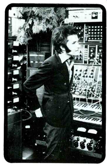
Walter Carlos, creator of "Switched on Bach" and "The Well-Tempered Synthesizer," uses the Dolby System.
Mr. Carlos says, "The raw materials of electronic music the outputs of my Synthesizer, for example are sounds which can be varied from striking purity to extreme complexity. After a desired sound is created, often with considerable effort, it must be preserved with care, to be combined later with others in a meticulous layer by layer process. The noises of magnetic recording are significant hazards in this regard, since they are particularly noticeable in electronic music. However, my experience confirms that the Dolby System effectively attenuates the noise build-up in electronic music synthesis. My studio at TEMPI is equipped with ten Dolby units, which I consider to be indispensible in my work." Whatever your recording activities, the dependable Dolby System can help you make good recordings even better. Now in use in over 100 companies in 21 countries around the world.
DOLBY LABORATORIES INC. 333 Avenue of the Americas, New York, N Y 10014, USA. telephone (212) 243-2525
cables Dolby labs New York
--------------------
JVC
The Outer Rotor Motor: Attains new heights in turntable efficiency
JVC announces the outer rotor motor-destined to revolutionize the record player as we know it.
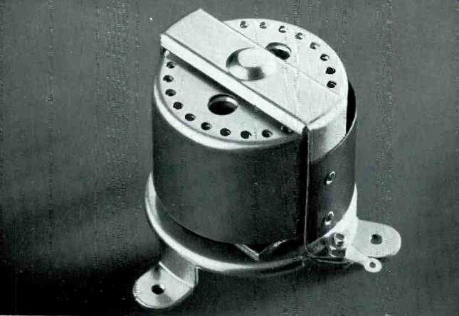
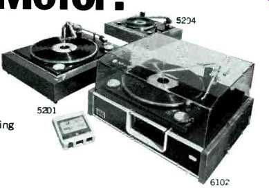
Bigger and substantially heavier than the old inside rotor type, the outer rotor motor achieves new heights in efficiency while cutting power consumption in half. Among its advantages are greatly improved balances for a significant reduction in vibration and more even rotation, and completely eliminated hum, thanks to the much reduced leakage flux.
The outer rotor motor is a feature of both the , JVC 6102 and the 5201. The 6102, a beautifully-styled 4-speed component.,. offers the option of records or 8track stereo tapes and sells for just $139.95 The 5201, another 4speed model, is a bargain $94.95.' JVC's 5204, with 2pole synchronous motor, is priced at just $59.95.* If greatly improved turntable efficiency makes sense to you, drop in and see your nearest JVC dealer. Only he is offering it.
*Suggested list prices
Catching On Fast
JVC America, Inc., 5035, 56th Road, Maspeth, New York, N.Y. 11378 A Subsidiary of Victor Company of Japan, Limited, Tokyo, Japan
-------------------
DYNACO SYNERGISM OR HOW TWO UNITS COMBINE FOR EVEN GREATER VALUE


SCA-80 _ STEREO 80
$169.95 Kit
$249.95 Assembled
$159.95 Assembled
PAT4
$119.95 Kit
$89.95 Kit
$129.95 Assembled
We have always tried to give outstanding value at Dynaco; and when we work on new designs, our primary objectives are quality and value--quality second to none, and prices far below the levels of competitive quality. Following this philosophy, we have designed our newest power amplifier, the transistorized Stereo 80, in the tradition of the famous Dynaco Stereo 70-extreme reliability, conservative operation and specifications, outstanding quality, and moderate price. The Stereo 80 is compact (it fits any remote space, but is handsome enough to keep on display), cool-running, simple, and elegant.
It delivers 40 watts continuous power per channel, with both channels operating simultaneously, from 20 Hz to 20 kHz.
The Stereo 80 and our PAT4 preamplifier create an outstanding combination which delivers crystal clear sound, free of noise and distortion, and with excellent flexibility as the control center for the most complete hi fi installation.
Further, we have combined these units into a single, transistorized integrated package, the SCA-80, and through careful design have achieved SYNERGISM*, the combination giving even greater value than the sum of its parts.
The SCA-80 has all the qualities of the Stereo 80 plus the performance and many of the features of the PAT-4-center-out tone controls, low noise, multiple input facilities, headphone output, center-speaker output without the need for a separate amplifier, and so on. It provides complete control facility and yet it is simple to operate with a basic two-knob control action for those who do not require sophisticated features such as loudness, filters, blending, and other subtle variations.
The SCA-80 gives quality plus compact flexibility. The Stereo 80 plus the PAT4 gives quality, increased flexibility for installation, and greater range of control function. The Stereo 120 plus the PAT4 gives all this plus extra power plus the benefits of a stabilized highly filtered power supply which makes performance independent of power line variations. In all these choices, quality and value are outstanding-and in the SCA-80, the synergistic benefit enhances the value of the unit.
"SYNERGISM-"Cooperative action of discrete agencies such that the total effect is greater than the sum of the two effects taken independently . . .
3060 JEFFERSON ST., PHILA., PA. 19121
--------------------
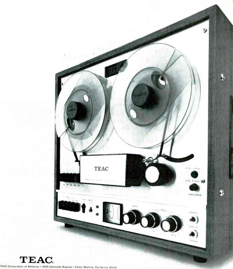

A-15000 Exclusive triple-motored drive system 4 precision heads for instant off-the-tape monitoring Mike-line mixing 4 independent amplifiers Automatic tape lifter All-push-button controls, automatic shutoff Stereo echo for special sound effects Choice of cabinet or portable styling Play it by ear.
You'll like what you hear.
And you can go right on hearing it, too. Because our A-15000 tape deck comes complete with carefree automatic reverse. In other words, this machine doesn't care whether it's coming or going.
It's a standard four-track model with all the quality TEAC is famous for. And plenty of unique features.
like the popular ADD recording for simultaneous playback and recording on separate tracks.
Yes, you'll like what you hear on this one. Including the price. (That part sounds almost as good as your favorite tapes.)
TEAC. TEAC Corporation of America 2000 Colorado Avenue Santa Monica, California 90404
-----------------
Only Pickering offers
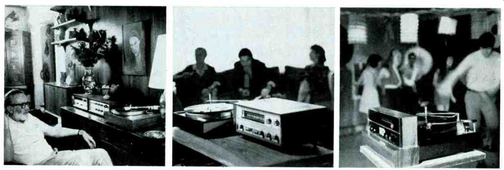

'Dynamic Coupling Factor.. your assurance of greater listening pleasure
A sophisticate who can afford the finest in stereo components and equipment, would select the Pickering XV15 Cartridge labeled 750E, 400E or 350. They're the proper ones to deliver "100% Music Power."
With the more simple equipment that characterizes today's informal living, the XV15 with a DCF of 150 or 200 will assure "100% Music Power."
A Pickering XV15 Cartridge with a DCF of 100 or 140 will guarantee "100% Music Power" on the type of set up that the young in your house use for dancing or listening.
The Dynamic Coupling Factor is an index of maximum stylus performance when the cartridge is related to a particular type of playback equipment. This resultant number is derived from a Dimensional Analysis of all the parameters involved. To select a pickup for a professional manual turntable, with its sophisticated, dynamically balanced tone arm, tracking at an ultralight force, a higher DCF index would be required than, say, for a pickup to be used in an ordinary record changer. For maximum distortion-free response, this index to application relationship properly determines maximum stylus performance in your playback equipment.
100% music power is assured at all frequencies linear response from 10 to 20,000 Hz virtually a straight line due to the extremely low mass of its moving magnetic system 1/5 to 1/10 of ordinary pickups.
There are seven DCF rated XV15 models. Each is equipped with the famous patented VGuard "floating stylus" the easily replaceable stylus assembly that protects the diamond and record while it plays. In addition each model includes the DUSTAMATIC brush that automatically cleans the record groove while it plays.
PICKERING--For those who can HEAR I the difference
THE NEW PICKERING XV15 1750E. PREMIER MODEL OF THE XV-15 SERIES. TRACKS AT 1/2 TO 1 GRAM. DYNAMIC COUPLING FACTOR OF 750 FOR USE IN FINEST TONEARMS. $60.00. OTHER XV115 CARTRIDGES FROM $29.95. PICKERING & CO., PLAINVIEW, L.I., N.Y.
-------------------
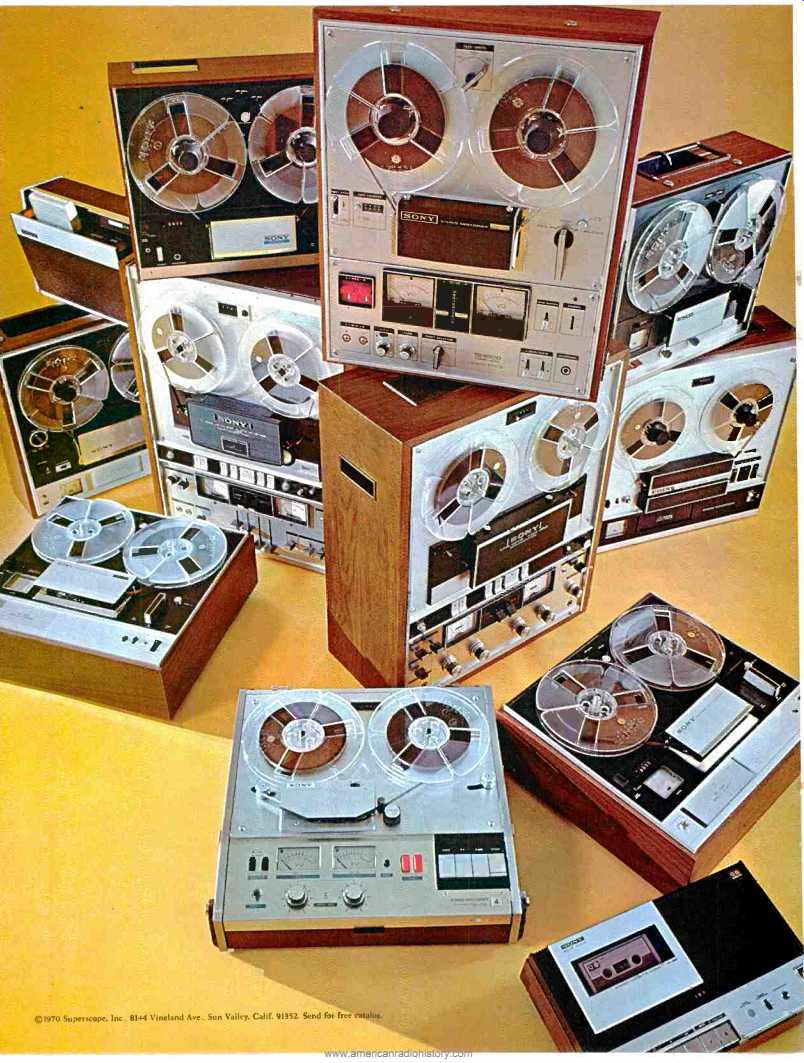

How to recognize a stacked deck.
No matter how elaborate your home stereo sound system is, it's incomplete without a tape deck. And Sony/Superscope brings you the most complete line of stereo tape decks in the world. Decks that fit all pocketbooks, that suit particular systems, that meet specific needs. And every Sony/Superscope deck--regardless of price--is the finest money can buy. Each instrument is flawlessly crafted, with rigorous testing at every step of construction. Then each instrument undergoes a complete series of quality assurance tests performed by skilled technicians at one of the most modern and sophisticated tape recorder test facilities in the world. So you may be sure that the Sony/Superscope product you purchase will give you years of troublefree service.
The Sony/Superscope deck that's exactly right for you is at your dealer's now.
SONY
You never heard it so good
-----------------
AR
Because of their exceptional accuracy, Acoustic Research speaker systems are usually chosen for special scientific applications.
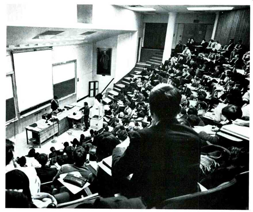

One of the world's leading medical schools has recently solved a long-standing problem in its training of first-year students: how to enable a lecturer and hundreds of listeners to hear simultaneously the heart sounds of a living patient. Usable microphonic pickups exist; the difficulty arises because most of the sound in a heartbeat is in the range below 40 Hz. At these very low frequencies, even many speaker systems which seem to have "good bass" are unable to provide results comparable to those of a doctor's stethoscope. The stethoscope, simple as it is, couples the physician's ears directly to the patient's chest, and can, in principle, convey acoustic pulses near 0 Hz. It is this kind of extended low frequency response which was needed, but individual listening devices were out of the question; they would not allow lecturer and students to hear and recognize the same abnormalities without ambiguity.
The problem was solved by the school's purchase of four standard full range AR1x speaker systems and an AR amplifier; the latter is used with all controls "flat". Despite the large size of the lecture hall, the heart sounds are clearly audible to all students, and levels can be produced which literally rattle the doors and windows of the amphitheater.
Our best system for music reproduction is our AR3a; it has the same low frequency characteristics as the AR1x, but includes our most accurate midrange and high frequency drivers also. Other AR speaker systems are described in the free AR catalog.
Acoustic Research Inc.
24 Thorndike Street, Cambridge, Massachusetts 02141
--------------------
" ... the Dynaco PAT4 is unsurpassed .. . a remarkable unit and unmatched at anywhere near its low price . . . (Stereo Review, January 1968)
DYNACO PAT4
$89.95 kit
$129.95 assembled
A separate preamplifier can offer superior performance and greater flexibility than available on any integrated control amplifier or receiver. How well did Dynaco succeed with its PAT4? Here's what two of the most respected publications say.
The Stereophile, Vol. 2, No. 9, 1968
"With all of its tone controls and filters set to Flat, and feeding any high-level input, we were simply unable to tell whether we were listening to the original 'raw' signal or the output from the PAT4. In this respect, we cannot see how any preamp, present or future, could surpass the PAT4."
Julian Hirsch in Stereo Review, January, 1968 " . (the PAT4 has) an extraordinary degree of operating flexibility ... (and) in sonic quality, we would unhesitatingly say that the Dynaco PAT4 is unsurpassed by any preamplifier we have seen. It is a remarkable unit and unmatched at anywhere near its low price of $89.95 in kit form or $129.95 factory-wired."
The Dynaco PAT4 preamplifier can be used with any power amplifier, tube or transistor, like the Stereo 120 (60 watts rms per channel) or new Stereo 80 (40 watts rms per channel). Owners of Stereo 70's can also derive the full measure of enjoyment from the PAT4.
Send for literature or pick some up at your dealer where you can see and hear Dynaco equipment DYNACO -- 3060 JEFFERSON ST., PHILA., PA. 19121
-------------
Sony
You pay for what you don’t get
Like the inaudible rumble. The result of a motor that runs at approximately 1/6th the speed of conventional motors to reduce intensity of motor vibration. And a belt-driven system that effectively isolates any possible remaining vibration from the turntable platter.
Like the absence of distortion, wow and flutter. The result of a servo-control motor that assures precise speed accuracy and can't be affected by line voltage fluctuation. The electronic servo and the low-speed DC motor reduce total wow and flutter to only 0.08% rms, and rumble to 60dB below the Audible Rumble Loudness Level (ARLL).
Like no troublesome mechanical linkages that can cause drag on the arm and result in distracting sour notes. The remarkable, new Sony Magnetodiode (SMD) initiates movement of the arm electronically, rather than mechanically.
Like nothing added to the recording that isn't on the recording already.
So, you see, you pay for what you don't get.
On the other hand, so you don't feel cheated, and don't feel that you are getting nothing for your money-you do get a superb playback system. It includes turntable, precisely balanced tonearm of low mass design that tracks flawlessly, oil finish walnut base and dust cover. You also get the convenience of semiautomatic operation.
Automatic shut-off after a record has been played. Automatic shut-off while the record is in play, by simply pushing a button or just returning the arm to rest.
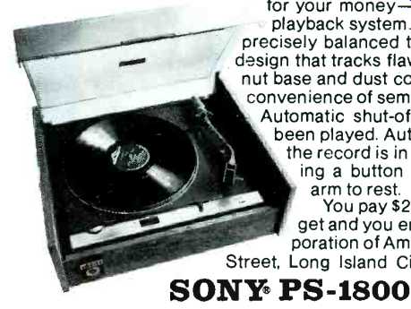
You pay $200 for what you don't get and you enjoy it too. Sony Corporation of America, 47-47 Van Dam Street, Long Island City, New York, 11101
SONY.
PS-1800
------------------
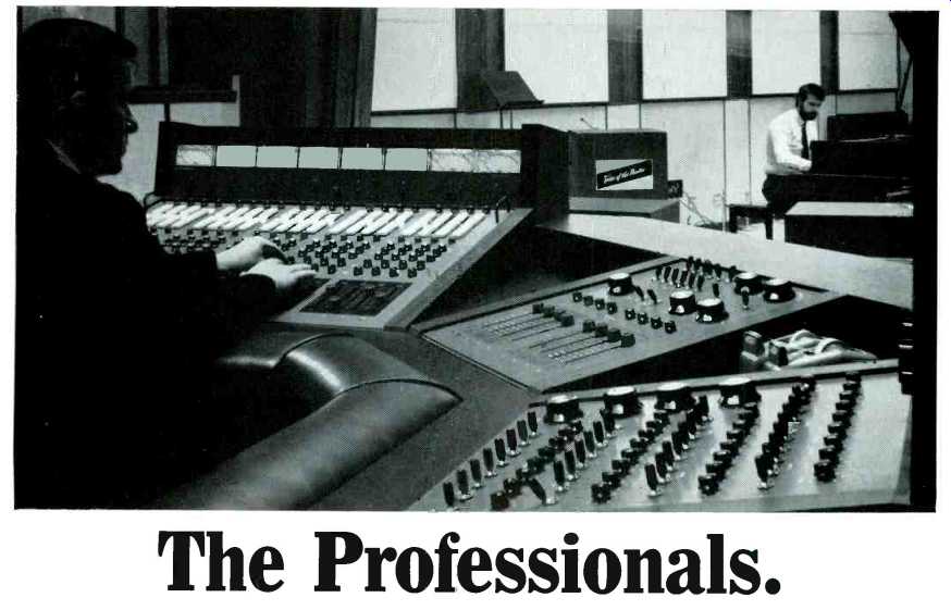
The Professionals.
Bill Bell is known as "The Ear” He's the owner of Bell Sound Studios, Hollywood. Bill does commercials, some of the best. You've heard a lot of them. He orchestrates each one, every element of sound from the soft spoken solo voice of Marvin Miller to the high dB blare of acid rock.
Bill's fussy about sound, and so are his engineers. So are the advertising agency production men, the creative people and the account executives. If you're going to take three or more hours to get the right sound in sixty seconds of commercial, you want to make sure the sound is the best possible.
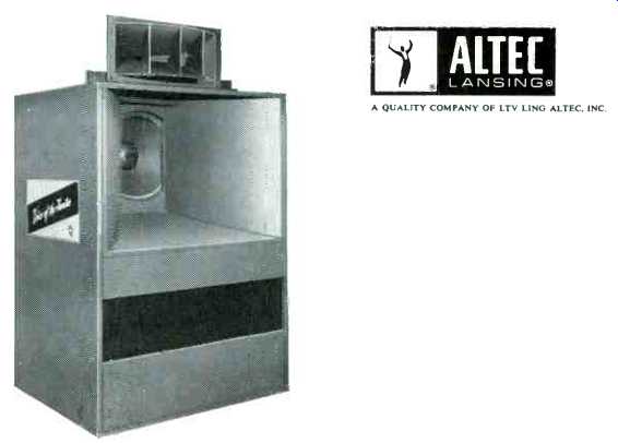
So, as a starter, Bill uses Altec "The Voice of the Theatre"® speaker systems, sixteen of them. And in his custom consoles, Bill Bell also uses Altec audio controls. Again, because he thinks they're the best.. After over thirty years of developing sound systems for the broadcast and motion picture industries, that's a nice reputation for Altec to have.
Specifically, each new Third Generation Voice of the Theatre speaker system features a 15" low frequency speaker that's the finest made. It has a 10 1/2 pound magnet structure, a cast aluminum frame and a 3" edge-wound voice coil of copper ribbon. All this plus the efficient new Symbiotik diaphragm-provides outstanding bass and transient response, and as much as two times more power handling capability than previous designs. The 18" massive cast-aluminum sectoral horn has a very wide sound dispersion angle at all frequencies.
The driver. It works from 500 to 22,000 Hz in the A-7-500-8. (The A7 crosses at 500 Hz.) It's so efficient, there's need for only one crossover in the system which eliminates those high frequency peaks and dips. All this means the crispest, cleanest, most undistorted sound you can get from low end through the high.

For complete specs on our sound equipment, just write to:
Altec Lansing, 1515 So. Manchester Ave., Anaheim, California 92803.
ALTEC LANSING.
A QUALITY COMPANY OF LTV LING ALTEC, INC.
---------------------
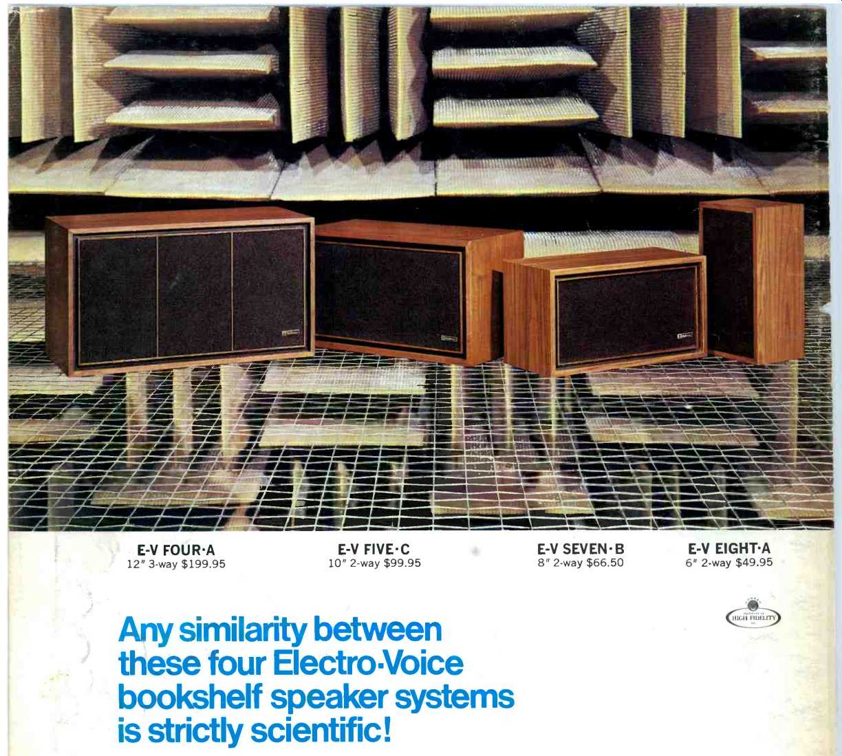
Any similarity between these four Electro Voice bookshelf speaker systems is strictly scientific!
EV
These four speaker systems share a surface beauty. But don't be misled. Underneath where it counts there are scores of important differences.
There have to be.
Because what's right for a small system may be all wrong for a big one. And what works well in a 2way system may be poison for a 3way. (Even a little change, like just I" more cabinet, can upset the design of every component inside.) Of course not everybody can afford to design every speaker in their line from scratch, the way Electro-Voice does. But then, not everybody has a scientific computer that pre-tests hundreds of ideas on paper to find the few good enough to build.
And not everybody has a huge anechoic chamber (like the one above) to prove the superiority of each design. Nor the staggering array of test equipment that goes with the chamber. Or most important--the engineering talent and musical sensitivity to take full advantage of these unique laboratory facilities.
When you select an EV speaker system regardless of size or price you can be certain it truly represents the state of the art ... and good value to boot.

Anything less would be a cop-out.
But don't take our word for it. Listen.
Compare. The difference you see and hear is what high fidelity is all about.
ELECTROVOICE, INC., Dept. 204A 602 Cecil Street, Buchanan, Michigan 49107
A SUBSIDIARY OF GULTON INDUSTRIES, INC.
high fidelity systems tuners, amplifiers, receivers public address loudspeakers microphones phono needles and cartridges aerospace and defense electronics
==========
(Audio magazine, Feb. 1970)
= = = =