by W.J.J. Hoge [Harrison Systems, Inc., Nashville, Tenn. 37202]
Some of the Gentle Readers of Audio who remember my previous articles may be wondering what a loudspeaker engineer is doing writing about microphone preamplifiers. After all, the two devices are at just about the opposite ends of an audio system. Long before I worked with loudspeakers, I worked in the recording industry here in Nashville. Part of my background includes experience as a circuit designer, and I have also worked as a recording engineer. When I decided to move back home to Nashville, I decided to combine those two parts of my background so I am now working with a company which builds large, sophisticated recording consoles.
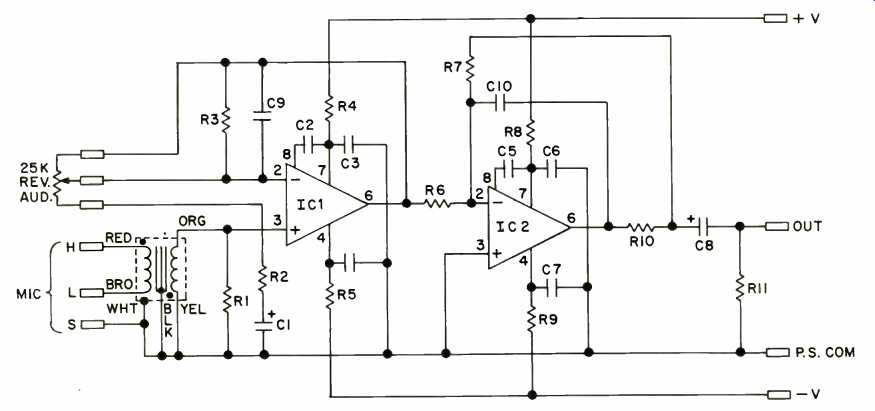
Fig. 1--Schematic of microphone preamp.
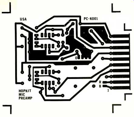
Fig. 2--Pattern, at one-to-one size, for circuit board.
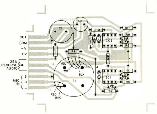
Fig. 3--Component placement on circuit board.
The quality of recording equipment has been significantly improved over the past few years. When I first started mixing records (back in the '60s), the equipment did not perform especially well by today's standards. For example, it was not uncommon for equipment with rated distortion of 0.5 percent to be considered not only acceptable but pretty damn good. The state of the art has advanced well beyond that.
Today every record you listen to has at least one thing in common with all others. Whether it's from a modern, multi track studio recording or one made on location using simple techniques, the signals from the microphones had to be amplified before they could be used to drive the tape recorder or (in the case of the music business' most recent giant step backward) the disc cutter-head amplifier directly. The serious amateur recordist does not have much available to him in the way of microphone preamplifiers which meet the standards of those in modern studio equipment. In this article I'll de scribe one which you can build. It is suitable for use with all common types of microphones with low impedance outputs.
In amplifying the microphone's signal, the preamplifier must not add any extraneous signals, such as noise or distortion. It also must have sufficient bandwidth to pass all the useful information which comes from the microphone, but it should also have a limited bandwidth to help prevent unwanted signals (such as radio frequency interference) from entering the system. For naturally occurring musical signals, the lowest frequency commonly generated is about 41 Hz, however, the lowest tone which comes from a piano is 27.5 Hz. A professional-grade device should be able to pass that piano fundamental. The upper limit of the ear's spectrum is on the order of 20 kHz in young people with good hearing.
Information theory tells us that if we try to transmit more information than the receiving end of a system can use, we are wasting our time. Thus, response to 20 kHz is adequate.
Professional-grade microphones of varying types provide output signals of widely varying nominal levels. Ribbon microphones often have sensitivities low enough to yield nominal levels on the order of-60 dB (re: 0.775 V). (Author's Note: V one of those quasi-magical numbers which pops up in audio from time to time. A signal with an rms potential of 0.775 V will cause a 600-ohm resistor to dissipate 1 mW of power.) Condenser microphones are commonly available with output levels on the order of -30 dB. Thus, it is obvious to the most casual observer that a wide range of gain adjustment should be available in our preamplifier. Usually a gain of + 60 dB is good with ribbon microphones; a gain of +20 is about what is required with condenser microphones placed near loud sources. We now have a set of design specifications for our preamplifier. The bandwidth should be from 27.5 Hz to 20 kHz, the gain from +20 to +60 dB, the distortion and noise held to minimum levels, and the input impedance should be compatible with low-impedance micro phones. As an additional specification, we ought to specify the output signal level available and the minimum load impedance. Let us say that the preamplifier should be capable of delivering an rms signal of 6 V when operating into a 600-ohm load.
Most high-quality pre-amplifiers use input transformers. An input transformer which is properly designed can perform several useful functions. First, it can serve as an impedance-matching device between the microphone in the input stage of the amplifier. The purpose of this match is not to achieve maximum power transfer but rather to minimize noise generated in the input stage. There is an optimum range of source impedances for any particular amplifier for best signal-to noise ratio. Low-impedance microphones have output impedances well below the optimum range for most devices.
A second function that the transformer can perform is limiting the bandwidth of the input signal. Transformers exhibit both low and high frequency roll-off. This can reduce low frequency disturbances from such sources as traffic rumble and high frequency disturbances from such sources as your local Citizens Bandit (CB).
Finally, a transformer can provide voltage gain. In fact, an input transformer that would properly match the output impedance of a microphone to the impedance of a typical input stage required for best noise performance, would be a step up transformer.
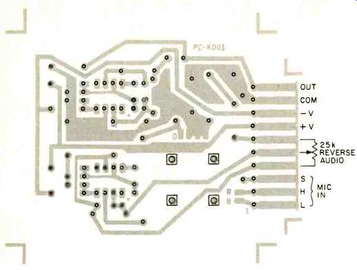
Fig. 4--All holes should be drilled with a #60 bit except the four transformer
holes in the squares which should be made with an eighth-inch bit.
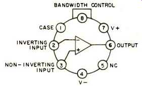
Fig. 5--Pin locations on the 911 op-amp.
Caution should be used with these devices as they are sensitive to electrostatic charges.
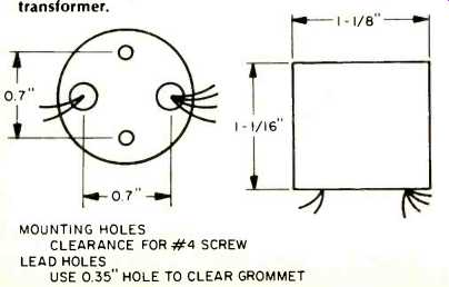
Fig. 6-Shape and hole locations of Jensen transformer.
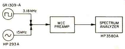
Fig. 7--Set up for DIM 100 test. The output of the square-wave generator is
bandlimited at 100 kHz.
The particular input transformer selected for this preamplifier is the JE-115K-E made by Jensen Transformers. It has extremely low leakage inductance. When its secondary is loaded with 10 times its characteristic impedance, it exhibits very low overshoot and does not require an RC resonance damping network when it is used with an amplifier with a two- uS lead compensation network in its feedback. The input impedance of the primary is about 1400 ohms when the secondary is terminated with 150 kilohms. This provides a proper termination for low-impedance microphones. The secondary presents a source impedance of about 20 kilohms to the input stage of the amplifier. The rate of distortion increase for low-frequency, high-level signals is very low. The voltage gain is +20 dB.
Based on the characteristics of the input transformer, we can specify the rest of our circuit. We need an amplifier with gain adjustable from 0 to +40 dB, an input stage which operates with low noise when used with a 20-kilohm source, a high-frequency roll-off equivalent to that provided by a two-uS phase lead network in its feedback loop, and the capability of delivering a 6-V signal to a 600-ohm load. It is, of course, possible to design an amplifier which uses discrete components which will meet our specifications. However, if we can find an integrated circuit which can be used, we can save a great deal of design time and, perhaps, some money.
ICs have a bad name in the audio business. Some operational amplifiers which were designed for d.c. instrumentation use have been misapplied to audio purposes for which they were unsuited. There do exist a few monolithic op-amps which can be used (with care) in audio systems. One such amplifier is the Harris excellent noise characteristics. It is a wide bandwidth device and is capable of delivering a 7-V signal to a 500-ohm load. Figure 1 shows our microphone preamplifier using the 911.
Note that we have used two of the ICs. The first stage provides the voltage gain not provided by the transformer.
The second stage provides the high-frequency response shaping for minimum overshoot.
The first stage has its gain normally set by the 25-kilohm reverse audio-taper pot shown in the schematic. When the wiper of the pot is at the bottom, the stage's gain is set by the ratio of the total resistance of the pot to R2. This is 100 to 1 or +40 dB. When the wiper is at the top, the gain is unity. R3 provides feedback around the op-amp at all times. If the pot were not connected or if the wiper were to lift from element of the pot during rotation, the gain of the stage would drop to unity. In the case of the lifting wiper (a not untypical imperfection even in a good pot), the momentary gain drop is less ear shattering than a momentary gain rise to the open-loop gain of the op-amp.
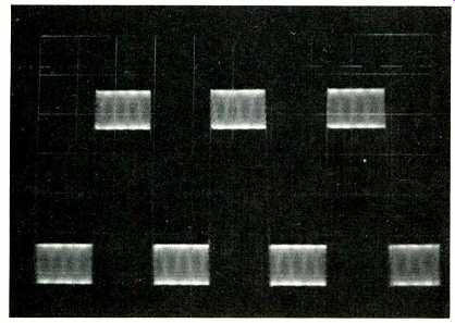
Fig.
8--DIM 100 test signal at the preamplifier output set for gain of 20 dB. Note
the minimal overshoot. (Vertical scale is 5 V/div.)
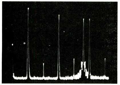
Fig. 9--Spectrum analyzer output for the DIM 100 test signal at the preamplifier's
output. All extraneous signal components above -80 dB were present in the input
signal.
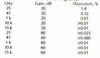
TABLE I--Gain and distortion vs. frequency.
The second stage is a unity-gain inverting stage. C10 in the feedback loop provides the appropriate phase lead compensation. R10 is a 100-ohm resistor in series with the output of the op-amp but inside the feedback loop. It provides protection from the effects of capacitive loads.
Figure 2 is a foil pattern which may be used to build the preamplifier, while Fig. 3 shows the location of the parts on the component side of the board. A small dot marks pin 1 of the ICs. The transformer is mounted using two self-tapping screws (provided by Jensen with the transformer). The primary and secondary leads come through the board in the other two holes underneath the transformer. The red and brown primary leads should be connected to the pads labeled A and B respectively. The orange secondary lead should be connected to the pad labeled O. The other secondary leads may be connected to the other three pads next to the O pad in any order. These pads are not drilled; place the lead against the surface and tack them down with solder.
A mixture of 1 percent metal-film and 5 percent carbon-film resistors are specified. The metal-film units are specified where noise performance or accuracy is required. Note the four jumper wires on the board. Don't leave them out.
The preamplifier will work from supplies ranging from ± 15 to ± 24 V. All of the performance tests below were performed with a ± 18 V supply. I recommend using that particular value in this design.
The frequency response was measured at both full gain (+60 dB) and minimum gain (+20 dB). In both instances it was +0, -1 dB from 15 Hz to 35 kHz. The -3 dB points were 8 Hz and 50 kHz, which meets our bandwidth requirements.
Rejection of r.f. was found to be excellent.
The harmonic distortion was measured at both gain levels when driving a 600-ohm load with a 6.2-V signal. Table 1 shows the results of the test.
The dynamic intermodulation distortion (transient IM, plus slew induced distortion, plus several other forms of nastiness we are only just starting to figure out) was measured using the DIM 100 method. The distortion was less than 0.01 per cent; Figs. 8 and 9 show the signal at the output of the preamplifier and the spectrum analyzer readings. Happy building!
-------------------
Parts List

C1 C2, C5 C3, C4, C6, C7 C8 C9 C10 R1 R2 R3 R4, R5, R8, R9, R10 R6, R7 R11 IC1, IC2 470 pF, 35 V electrolytic 10 pF ceramic 10 nF ceramic 100 pF, 26 V electrolytic 20 pF ceramic 220 pF ceramic 150 k, 1% metal film, RN55 or equiv.
249 ohm, 1% metal film, RN55 or equiv.
1 M, 5% carbon film, Vs W 100 ohm, 5% carbon film, 1/4 W 9.09 k, 1% metal film, RN55 or equiv.
100 k, 5% carbon film, 1/4 W Harris HA2-911-5 op-amp
T1 Jensen transformer JE-115k-E Misc. 8-pin DIP sockets, 10-pin PC edge connector, 25k reverse audio pot Complete preamplifier kits, including all electronic parts, the PC board, IC sockets, a 10-pin PC edge connector, and input transformer, are available from Hopkit, P. O. Box 22964, Nashville, TN 37202. The price is $79.50.
Harris 911 op amps are available for $4.00 each. PC boards with gold-plated contact fingers are available for $15.00 each. The Jensen JE-115K-E is available from Jensen Transformers, 1617 N. Fuller Ave., Hollywood, CA 90046 for $28.53 each.
------------------------
(Source: Audio magazine, Feb. 1979)
Also see:
The Advent MPR-1 Microphone Preamp, by Frederick M. Gloeckler, Jr. --A two-channel, transformer input, control-less amp for Advent's 201A
Link | --Build a Stepped Volume Control (Feb. 1979)
Build an Amp Strapping Circuit (Feb. 1979)
Build a moving coil phono pre-preamp (Feb. 1978)
A Comparison of Preamplifier Construction Projects, by S. A. Rossmassler--A reader builds four units with helpful tips
= = = =