by W. Marshall Leach, Jr.
[Associate Professor, Georgia Institute of Technology, School of Electrical Engineering, Atlanta, Georgia 30332]
One of the many problems that often plague those who like to build their own audio gear is obtaining a high-quality volume control. Most potentiometers on sale in electronics stores either are not the correct value, have an incorrect taper, or are so cheaply made that they make a "scratchy" sound when the volume is changed. If a dual or ganged control for stereo is sought, the problems are even worse. Provided one can be found, almost inevitably the two sections mistrack severely, often by more than 10 dB at low volume settings. Good volume controls can be found if one has the patience to locate them and the money to pay for them.
However, there is an inexpensive alternative ... constructing one with an easy-to-obtain multi-position switch. Although the control may not have the slick feel of more expensive ones, its attenuation can be designed for precise volume control and the tracking of the two stereo channels will be virtually perfect with 5 percent carbon-film resistors for the attenuator elements.
The switch which has been selected for this project is a Centralab Model PA-4002 two-pole, 24-position shorting switch. With one position for the input, one for the output, and one for the ground connection, it is possible to connect a total of 22 resistors to form a 23-positon stepped attenuator that varies from zero to infinite attenuation in predetermined steps. The procedure which will be described for calculating the resistor values is straightforward so that with the aid of a scientific calculator, the resistor values can be easily calculated for an arbitrary number of steps, an arbitrary taper, and any value of total resistance. A simple program, which has been written for the Texas Instruments TI-59 programmable calculator, will also be given.
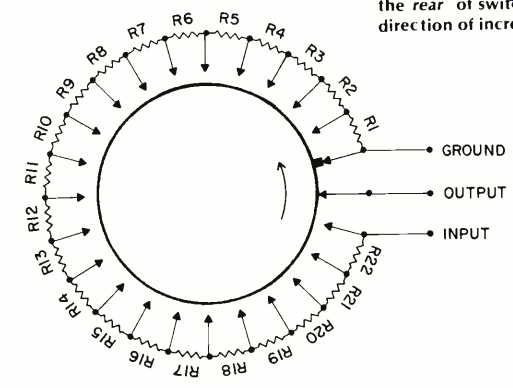
The circuit diagram of the stepped attenuator is given in Fig. 1. This shows the resistor network in a circular array as it would appear on the Centralab switch when viewed from the rear. Let the position of the wiper be denoted by the integer n, where n varies from 0 to 22. At position 22, the wiper is connected to the input and the attenuation is zero.
At position 0, the wiper is connected to ground, and the attenuation is infinite. For any intermediate position, the attenuation in decibels is given by the equation:

(eqn. 1)
where R is the total desired resistance of the attenuator and n is the position of the wiper. Given the value of R and the value of a n for each position, this equation can be solved for each resistor in the array.

Fig. 1--Circuit diagram of one channel of the volume control. View is from
the rear of switch. Arrow indicates direction of increasing volume.

above: View from behind the control shows that care is required to keep the
resistors from shorting either against one another or against other terminals.

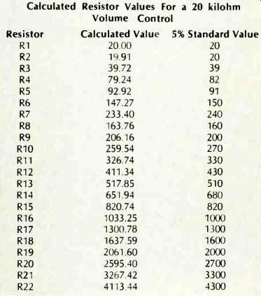
Table 1--Calculated Resistor Values For a 20 kilohm Volume Control
The first step in solving Equation (1) is to divide by 20, take the antilog, and then multiply by R. This gives

(2)
To determine each resistor value, R1 is first solved for by letting n = 1. This gives:
 (3)
(3)
To find R2, Equation (1) is evaluated for n = 2 and the value of R1 determined from Equation (3) is subtracted to give
 (4)
(4)
This procedure can then be repeated to solve for the remainder of the resistor values in the network.
The TI-59 calculator can be easily programmed to perform the resistor calculations. One possible program to do this is as follows:

In register 00, the total resistance of the attenuator is stored before running the program. The numerical value 0 should be in registers 01 and 02. To calculate the resistor values be ginning with R1, the desired attenuation in dB for each step on the switch is entered and the R/S key is depressed. For the last resistor value, 0 dB is entered and R/S is depressed.
The program has been used to calculate the 22 resistors which can be accommodated on the Centralab switch for the recommended 20 kilohm volume control for the wide bandwidth preamplifier described in [1]. The taper was chosen to be 6 dB per step for the first three positions, 4 dB per step for the next three positions, and 2 dB per step for all others. This gives a total attenuation of 60 dB for the first position, 54 dB for the second, 48 dB for the third, 42 dB for the fourth, 38 dB for the fifth, 34 dB for the sixth, 30 dB for the seventh, 28 dB for the eighth, etc. The calculated values of the resistors are given in Table 1. They can be easily converted to any desired total resistance without the aid of a scientific calculator by dividing each resistor value by 20 and then multiplying by the desired resistance in kilohms. Should a different taper or total number of steps be desired, the equations must be solved for the resistor values.
In constructing the stereo volume control, care should be taken to prevent any one of the 44 resistors from shorting against one another or against a switch terminal to which it is not soldered. Because the switch terminals may be slightly corroded, it may be difficult to get a good solder joint with out using excessive heat which could damage the resistors.
To prevent this, a suede brush can be used to clean the terminals and the solder dipped into soldering paste before soldering each terminal. A good solder joint is one for which the solder has flowed onto the terminal and which is shiny after the solder cools.
Before soldering the first resistor, it is best to double check and verify that the switch is being wired so that clockwise rotation of the shaft increases the volume. In addition, the two switch stops must be set so that when the shaft is fully counterclockwise, the wiper output terminal is connected to the ground terminal. When the shaft is fully clockwise, the wiper should be connected to the input terminal. Directions for setting these stops come with the switch. Because the switch is stiff when new, a drop of oil on each of the ball bearings that ride in the switch detents may loosen things up.
However, in time the switch will loosen up and be easy to rotate. One word of caution, the phenolic wafers in the switch are fragile! If the switch is dropped, one of these wafers can shatter ... this advice comes from experience. If this occurs, the damage can be repaired with epoxy glue.
Reference:
1. W.M. Leach, "Construct a Wide Bandwidth Preamplifier," Audio, Vol. 61, No. 2, Feb., 1977, pp. 38-48.
(Source: Audio magazine, Feb. 1979)
Also see: Build A Microphone Preamp (Feb. 1979)
Build an Amp Strapping Circuit (Feb. 1979)
Build a moving coil phono pre-preamp (Feb. 1978)
= = = =