Last month we examined the pick up used to generate laser light and read the light reflected from the Compact Disc surface. I find the pickup's design truly elegant-from the semiconductor laser to the beam splitter to the photodiode, hard-nosed and pragmatic engineering is evident throughout. Of course, the pickup is but one component in the larger system, and just as a phono cartridge is useless without a tonearm, the laser pickup's success rests on two other subsystems, the automatic focus and automatic tracking circuits. This month, I'd like to look at the design of the auto-focus system.
As we saw last month, the controlling optics for both systems are designed into the pickup; sophisticated servo systems, however, are needed to guide the pickup itself. The various manufacturers and their engineers differ as to exactly the best approach (and this is where patent lawyers enter the design process), but every CD pickup employs some kind of auto-focus, all of them constructed along basically similar lines.
A Compact Disc has in the neighborhood of 10 billion bits arranged over its 8,600 square millimeters of data area. Given that kind of density, and a laser reading beam whose diameter is 1.6 to 1.7 micrometers when it hits the reflective data layer, the beam must be kept tightly focused, within ±2 µm. Any unfocused condition would result in inaccurate data reading. Of course, even the flattest disc isn't perfectly flat; the disc specifications acknowledge this by allowing for a deviation of ±0.6 mm. Thus, the objective lens must be able to refocus as the disc surface wanders. A servo-driven auto-focus system manages this, utilizing the center laser beam, a four-quadrant photodiode, control electronics and a servo motor to drive the objective lens.
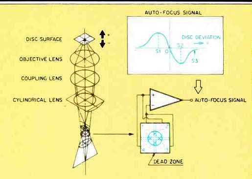
The unique properties of astigmatism are used to achieve automatic focusing (Fig. 1). Specifically, the cylindrical lens just prior to the photodiode performs the essential trick needed to detect an out-of-focus condition. As the distance between the objective lens and the disc reflective surface varies, the focal point of the system also changes, and the image projected by the cylindrical lens changes its shape. That change in the image on the photodiode generates the focus error-correction signal. When the disc surface lies precisely at the focal point of the objective lens, the image reflected through the intermediate convex lens and the cylindrical lens is unaffected by the astigmatism of the cylindrical lens, and a circular spot strikes the center of the photodiode. When the distance between the disc and objective lens decreases, the image projected by the objective lens and convex lens and the cylindrical lens moves further from the cylindrical lens, and the pattern becomes elliptical. Similarly, when the distance between the disc and the objective lens increases, the image moves closer to the lens, and an elliptical pattern again results, but rotated 90° from the first elliptical pattern.
The four-quadrant photodiode reads an intensity level from each of the quadrants to generate voltages (Fig. 2). If a focus-error signal is mathematically created to be quadrants (2 + 4) minus (1 + 3), the output-error voltage is a bipolar S curve, centered about zero. Its value is zero when the beam is .precisely focused on the disc; a positive-going error-correction signal is generated as the disc draws too near, and a negative-going error-correction signal as the disc moves away. As in any closed-loop system, such as the phase-lock-loop systems which keep motor speeds constant and accurate, the difference signal continuously corrects the mechanism towards a zero difference signal and thus, in this case, a focused laser beam.
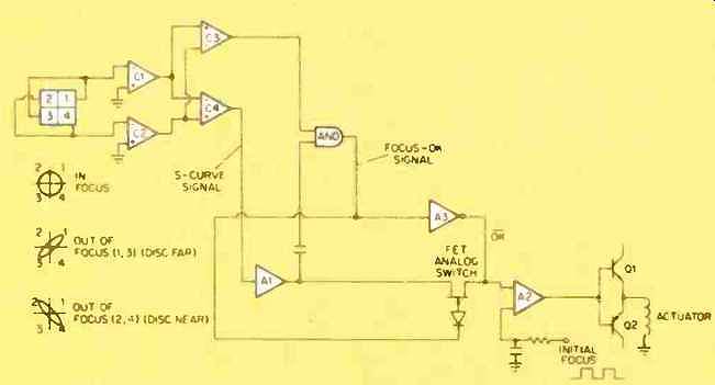
CD players use a servo system to move the objective lens up and down to keep depth of focus within the ±2-µm tolerance. An electronic circuit deciphers the error-correction signal and generates a servo-control voltage. This circuit uses comparators and amplifiers to generate the servo control. The four photodiode quadrants are divided into pairs (2 + 4, 1 + 3) such that greater intensity in quadrants 2 and 4 indicates the disc is too near, and in 1 and 3 too far, and these voltages are applied to the inverting inputs of two comparators, C1 and C2, whose non inverting inputs are referenced to ground. (The photodiode quadrants share a common ground.) The outputs are split to the inverting and noninverting inputs of two more comparators, C3 and C4. The output of C3 generates a check signal that indicates reflected light is being received at the photodiode. The output of C4 is the error-correction S-curve signal.
When the laser beam is accurately focused, comparators C1 and C2 see identical voltages at the inverting inputs, and their corresponding output voltages likewise are identical. Since there is no difference at C4, its output is zero, or set to a d.c. reference voltage. If the beam goes out of focus, a positive or negative deviation from the reference will occur, resulting in the S curve. The error-correction signal is amplified by A1 and A2 and passed through an analog switch, which has been turned on by the focus-check signal. The error-correction signal is then amplified at A3, which provides the proper drive current to the push-pull amplifier circuit (transistors Q1 and Q2). The actuator thus moves the objective lens to maintain the proper depth of field. Once this is achieved, the beam is focused, the error-correction signal is zeroed, and the actuator holds the lens position.
When a disc is first loaded, initial focus is obtained through a square wave signal generated by the system microprocessor. This signal consists of two square pulses, each with a period of 1 S. The square wave is integrated by a resistor and capacitor and causes the push-pull amplifier to move the actuator coil up and down twice. The laser is turned on as the actuator moves up the first time, and the actuator stops in a focused state when the focus-check signal is obtained. If no disc is detected the first time, the actuator tries again with the second pulse.
The system microprocessor will shut down if no disc is detected. When the auto-focus is not operative (if the door is open, the laser inoperative, etc.), the analog switch remains off and the inverted focus-check signal pulls the objective lens back, to prevent damage to the lens or disc.
The objective lens itself is displaced in the direction of its optical axis by a coil and permanent magnet structure (similar to that used in a loudspeaker, with the objective lens taking the place of the speaker cone). A two-axis actuator is used to accomplish this. The top assembly of the pickup is mounted on a base with a circular magnet ringing it. A circular yoke supports a bobbin containing both the focus and tracking coils. Control voltages from the focus-circuit drive transistors are applied to the bobbin focus coil, and it moves up and down with respect to the magnet.
The objective lens thus maintains its proper depth of focus. The other axis of movement, from side to side, is used to achieve tracking accuracy.

Fig. 1--The optics of a typical CD player's automatic focusing system.
The cylindrical lens turns the circular image into ellipses above and below the point of correct focus, creating differences in beam intensity over the four quadrants of the photodiode.

Fig. 2--Auto-focus control circuit.
After last month's praise for the virtues of simple engineering solutions, the auto-focus system might at first glance appear too complicated to qualify for an award. But when the problem's difficulty is considered, how concise the system is becomes evident. Consider that a Compact Disc revolves 3 1/2 to 8 times per second; any deviations from flat literally fly past the pickup, yet the objective lens must stay within 4 p.m of that varying surface, floating underneath, as it were. I think this auto-focus system satisfies that demanding criterion with true economy. And consider the benefits of such a feature. In the past we had to be content with a diamond needle dragging through a vinyl groove, whereas now, thanks to auto-focus, only light touches our medium-no pickup wear, no medium wear. I haven't dared to put a Compact Disc in my microwave oven to see just how much warpage my player will tolerate, but I think under normal use my player's auto-focus should keep the laser beam admirably focused on the music.
(adapted from Audio magazine, Feb. 1985; KEN POHLMANN )
= = = =