By DAVID HAFLER
Throughout the history of sound reproduction, there has always been uncertainty as to what degree of distortion and what types of distortion are audible. At one time it was thought that 5% total harmonic distortion was the threshold of audibility. Later, 2% was considered to be the goal to be reached to make distortion inaudible.
Now, high-quality amplifiers routinely specify distortion of less than 0.1% over the band from 20 Hz to 20 kHz. Despite this low distortion, many critical listeners claim to hear differences in performance which, if correctly identified, show that conventional distortion measurements are inadequate for indicating whether an amplifier's distortion is audible. This has led researchers to seek forms of distortion other than THD and IM, and some emphasis has been placed on transient distortion. However, this has still not given us the possibility of making a measurement and assigning a numerical value above which distortion may be audible and below which it is inaudible.
What is clearly needed is a method of determining whether distortion is audible in a given piece of equipment. This determination should be made using music as a source, and not limiting the investigation to steady-state signals such as sine or square waves.
If a listener could compare the re produced sound with the original, he could judge for himself whether the degree of distortion is detectable. This, however, is a test of the entire audio chain, including microphones and loudspeakers. One could not separately determine whether the amplifier produced audible distortion or not. To listen for an amplifier's distortion, one must have a reference for comparison.
The most accurate and convenient reference is the traditional straight wire. A straight wire has infinitesimal distortion and must, by its nature, be more accurate than any active device such as an amplifier. It immediately opens up the possibility of A/B comparison between it and the amplifier being tested. This can be done by putting two amplifiers in series, with the gain of the second one reduced to unity to match the gain of the straight wire; then the amplifier under test can be bypassed by switching the straight wire across it.
Figure 1 illustrates the simple setup for making this A/B test. One channel of a stereo amplifier can be used as the driving source for either the other channel or for the straight wire. Two subtle points must be observed in this experiment. First, there should be a loudspeaker load on the driving amplifier when the switch is in the "A" position. If that speaker load is not used, the test is less stringent, as the effect of the speaker on amplifier performance is not taken into consideration.
As we shall see later, a change in loud speaker load can indeed change the performance of an amplifier. Figure 1 shows the driving amplifier with its own speaker load when switched to "A" and with the test amplifier's load when switched to "B." Naturally, both loud speakers should be identical. A second requirement is that the speaker load for the driving amplifier must be isolated by putting it in a separate room. Otherwise, sound from that speaker will mask the sound of the amplifier-versus-wire comparison.
A/B testing is a valid and scientific method of comparison. However, it re quires judgment, and it has been criticized as being confusing, fatiguing and artificial. There is no question that what one person hears on an A/B test is not necessarily what another hears. There is considerable dissension about the merits of A/B testing. Since it is not universally accepted, it is fortunate that there is a more sensitive listening test for distortion. The preferred way to listen for distortion is to use what I call the straight-wire differential test (SWDT). Its arrangement is illustrated in Fig. 2. Here again, one channel of the stereo amplifier is used to provide a low-impedance driving source, and the gain of the other channel is set to unity to match the straight wire. In practically all power amplifiers, the input and output are in phase, so a transducer such as a loudspeaker can be connected from input to output in a differential mode. It is obvious that if input and output are identical, there will be no signal in the loudspeaker. Any sound that is audible after careful adjustment of the level will therefore be distortion.
What happens here is that the original signal is removed by subtracting the output from the input; this unmasks the distortion generated in the second (test) amplifier. This remainder includes nonlinearities such as THD and IM, all types of transient distortion, and amplitude and phase aberrations. In fact, it includes not only all known distortions, but also any which may be identified in the future. What it does not do is separate the types of distortion, so no weighting can be given to the more obnoxious ones.
When this test is performed on most amplifiers, one can hear grunge, harshness, edginess, grain, and other irritating sounds. One can also hear some relatively clean sounds which come mainly from amplitude and phase errors. These are not necessarily annoying, but they are inaccuracies, and the best amplifier designs should minimize them as well as the irritating factors.
The SWDT is elegantly simple, requiring no instruments. Its merits are obvious, but it is extremely difficult to apply because of its great sensitivity: A few minutes (fractions of a degree) of phase shift or a few milli-bels (hundredths of a decibel) of amplitude variation will show up as significant sound.
When a similar approach to amplifier testing was explored in the past (see "Testing Amplifiers with a Bridge" by Andrew R. Collins, Audio, March 1972), experimenters found relatively high levels of sound due to phase and amplitude variations. They did not consider these to be important, and they compensated the straight wire to minimize such variations. They made the assumption that phase variations were inaudible. This is disputable and controversial. I prefer to correct the amplifier to eliminate these aberrations, rather than to eliminate them from the signal source.
The SWDT gives the amplifier de signer a tool for improving the sonic performance of his designs. My own company's first amplifier to be de signed with the aid of this technique was the Hafler XL-280. Our approach was very conservative yet still innovative; we aimed for a wide-band, low-distortion design before the application of overall negative feedback, and before tweaking the final elements for minimum phase shift simultaneous with minimum distortion and adequate stability margin. Components were selected, bias currents were tested, phase compensation was added-all to get minimum sound output with the SWDT.
The XL-280 amplifier is completely symmetrical from input to output. It uses multiple power supplies with a common power transformer. There is a supply for each channel, and separate supplies for the Class-A driver stages and for the Class-AB output stages.
The input transistors are J-FETs in a cascode configuration. This provides a high degree of linearity with very low noise. The high input impedance of the J-FETs permits a higher impedance in put point for the negative feedback loop.
A driver stage follows, with current mirroring back to the first stage. This drives the emitter-follower stage, which provides a low-impedance source for the relatively high input capacitance of the multiple output section.
The output stage consists of two complementary groups of three MOS FETs in parallel, operating as source followers. These MOS-FETs are used because of their high speed, high degree of linearity, and extreme robustness; we have experienced minimal failures out of the hundreds of thou sands we have used in predecessor amplifiers.
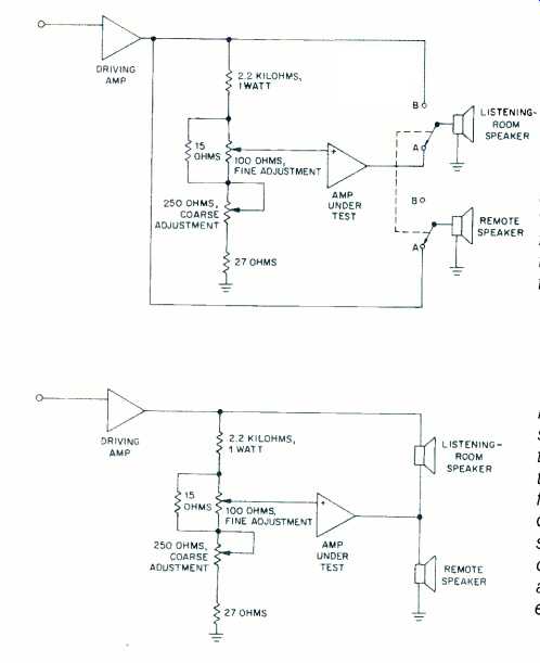
Fig. 1--Setup for comparing the sound of an amplifier to that NG-of a straight
wire. In ER switch position "A," listeners hear the driving amp's
signal through the straight wire; in position "B," hey hear it through
he amplifier under test.
Fig. 2--Setup for straight-wire differential test (SWDT). When the pots are adjusted or minimum sound output the speaker, only the distortion and phase and amplitude errors are heard.
The XL-280 uses a moderate amount of negative feedback in an overall loop, plus local feedback such as in the source-follower output stage. Though there are some who unjustly accuse negative feedback of being detrimental, I think it is safe to say that negative feedback, when properly applied, is always beneficial. Proper application involves using it with a very linear amplifier and assuring an adequate stability margin. Used in that way, negative feedback will reduce distortion and widen band-pass. Most important, it will also stabilize operating characteristics so that performance will not drift in use and so that there will be negligible variation from one production unit to another.
Phase compensation is used in the XL-280 to achieve minimum phase shift in the audio band, in order to get maximum sensitivity from the SWDT.
Achieving the goal of very low phase shift at high frequencies precludes the use of the customary output coil found in most amplifiers. To carry the control of phase to the ultimate, a phase "tweaker" is positioned so that it is accessible from outside the amplifier.
This network consists of a series resistor and capacitor trimmer which adjust a small peak in the range above 200 kHz. We have aimed for a maximally flat amplifier in the audio range, and maximum flatness leads to a slight ringing-at ultrasonic frequencies, fortunately, where it cannot affect the sound quality. Putting a peak of 3 or 4 dB at 200 kHz is a good exchange for obtaining essentially no phase shift in the 5- to 10-kHz range.
In testing the amplifier under many conditions, it was observed that the optimum point of operation, as deter mined by the SWDT, shifted with a change of loudspeaker. This was due to variations in loudspeaker impedance and the fact that the amplifier's internal impedance increased at high frequencies. A change in loudspeaker impedance made a small change in amplitude response. These small variations may be the cause of some of the sonic differences which are heard by "golden-ear" listeners. Fortunately, these small deviations can be readily compensated with the variable phase shift "tweaker" built into the amplifier.
The result is that, by using the SWDT, it is practical to compensate the individual system for the specific type of loud speaker in use.
For most listeners, the minute difference due to the final tweaking is unimportant, and a check using the A/B test of Fig. 1 confirms this. Most people can be satisfied with an adjustment based on any conventional speaker load, rather than the specific speaker they are using. However, for perfectionists and the most critical "golden ears," the XL-280 amplifier can be adjusted to its ultimate capability with specific loudspeakers, using the SWDT as the measuring tool.
As mentioned earlier, when we applied the straight-wire differential test to many amplifiers, the residual noise we heard included both grungy, irritating sounds, which were products of annoying distortion, and "clean" sounds which were the result of phase and amplitude aberrations. Phase and amplitude distortions, while not unpleasant to the ear, can affect the tonal balance and timbre of the sound and also influence the imaging and sound stage of the stereo performance. Applying the SWDT to the XL-280, we have found that when playing music above normal listening levels or when seated very close to the loudspeakers, there may be slight of al sound which are clearly identifiable by their cleanliness as phase and amplitude distortions. Their amplitudes are less than we have found in any other amplifier, and they are sufficiently minor to be completely masked by normal musical content; this is verified by the A/B test, which affirms that the XL-280 is indistinguishable from a straight wire. After tweaking for the individual loudspeakers being used, measurements show up to 70 dB of nulling in the mid-band and about 60 dB over the rest of the audio spectrum. This means that the total distortions do not exceed 0.1% over the audio band and confirms their inaudibility.
When the SWDT gives a substantial null on musical material at normal listening levels, the sonic accuracy of the amplifier cannot be improved. Any other amplifier which does not produce as deep a null on the SWDT, or which sounds different from one that does, is less accurate, regardless of whether its sound is pleasing. Once this level of amplifier performance is reached, further improvements in sonic quality must be obtained from elements in the hi-fi chain other than the power amplifier, although, of course, designers will still face the challenges of reliability, efficiency and economy in amplifier designs.
(Source: Audio magazine, Feb. 1987)
Also see:
Understanding Common-Mode Signals (Feb. 1988)
= = = =