By George W. Tillett
THE PRINCIPLES of electrostatics as applied to transducers have been known for many years and a complete electrostatic telephone system was actually demonstrated by one Dolbear at the Paris Electrical Exhibition as long ago as 1881! Electrostatic loudspeakers did not make their appearance until about 1925 and most of the development work for the next fifteen years or so was done in Germany by such pioneer as Ernst Klar and Hans Voght but American physicists like McLachlan, Kellogg and Hanna were also active in this field. In its simplest form an electrostatic speaker consists of a conductive-coated film diaphragm and a metal plate as shown in Figure 1. If a signal is applied between the two, the diaphragm will vibrate accordingly.
However, it will always move towards the plate as the voltage can only cause an attraction. Consequently, severe distortion will be produced and if a sine wave is applied the speaker will function as a kind of rectifier i.e. both positive and negative pulses will cause the diaphragm to move towards the plate. If a d.c. bias voltage is applied then the diaphragm will be partially compressed and a signal voltage can then cause it to move both ways about its biased position. The space between the diaphragm and plate must be very, very small and if an attempt is made to increase the distance so the speaker can work at lower frequencies then the efficiency falls drastically. Moreover, the distortion will increase due to the force varying with the diaphragm position. Thus, simple 'single-end' electrostatic speakers can only be used for high frequencies. A tripical treble unit popular in Europe in the late 30's and just after the War would measure about 3 inches square and the film diaphragm would actually rest on the metal plate.
In operation, such speakers would be connected directly to the anode of the output tube of the receiver, thus using a d.c. bias of some 200 volts.
Some of the more expensive units used two plates in a push-pull arrangement as shown in Fig. 2. Applied force is less dependent on diaphragm position and distortion will be much lower.
Obviously, the plates must be perforated to pass the sound. Full-range electrostatic speakers follow the same principles but there are certain problems.
To get down to the very low frequencies the gap between the diaphragm and plates must be large enough to allow the diaphragm to move. As mentioned above, this seriously reduces the efficiency. To some extent this can be made up by increasing the bias voltage but we eventually reach a limit determined by a corona or voltage breakdown. The practical maximum voltage is usually calculated by making the breakdown point equal to the bias voltage plus half the signal voltage. Even so, the diaphragm area has to be quite large to radiate enough power at low frequencies with reasonable efficiency.
Another problem that worried early designers was the distortion produced by the variation of the diaphragm charge. (See Fig. 3). If a strong signal pulls the film to one side then the capacitances of the two halves will become unequal and the total capacity will be increased beyond the normal C1 plus C2 figure because the net increase is greater than the decrease. This means that the corresponding charge will be higher and the diaphragm displacement will be greater than required. In other words, it would produce a kind of amplitude distortion progressively worse at low frequencies. Fortunately, the cure is fairly simple and it merely entails supplying the charge in the diaphragm via a high resistance. If the time-constant introduced is appreciable compared with the lowest frequency to be reproduced then there can be no significant current flow to or from the diaphragm and the charge is constant. Well almost, because there is yet another snag. Figure 4 shows a diaphragm pulled over to one side by the signal with one part nearer the plate P1. It is impossible to maintain 100 percent accurate spacing and so the charge tends to migrate to a point nearest a plate. What happens then? The voltage would fall elsewhere and so the effect is cumulative and could eventually lead to ionization and actual voltage breakdown--quite apart from causing distortion to. Again the cure is relatively simple and the answer is to make the diaphragm itself a high resistance so the charge cannot move about. Colloidal graphite or vacuum formed gold are two materials used and typical resistance is between 50 and 100 megohms per inch.
How about dispersion? A push-pull speaker will have a figure-of-eight, or doublet configuration although experimental models have been made with the rear radiation suppressed--or partially so. If the width of a flat sound source is equivalent to more than one wave length of the lowest radiated frequency, dispersion will be poor with lobes and beaming. One solution is to curve the radiating surface by using several diaphragms spaced in the form of an arc.
Another method is to use narrow strips connected as shown in Fig. 5. All the signal is fed to the center pair and resistors progressively reduce the levels at each side. A separate bass diaphragm would have to be employed and in the Quad model this is in two sections placed each side of the central treble unit. The step-up transformer is specially designed to also act as a cross-over by the ingenious method of using the leakage inductance in conjunction with the capacity of the actual bass unit. Rolloff is about 12 dB per octave.
It has been said that the diaphragm of an ESL does not `break-up' as it is driven as an entity. This is not true because the mechanical impedance is not constant due to the edge clamping where it is partly stiffness controlled.
It can be shown that nodes and anti nodes do exist just as in cone speakers The inherent distortion of an ESL is very low and Professor Hunt quotes figures of less than 0.5 percent second harmonic under worst conditions of unbalance a . Transient response is also extremely good as the moving mass is small. On the other hand, overall efficiency of models at present available is still on the low side--probably not a serious disadvantage--and extreme low frequencies cannot compare with good dynamic systems having 15- or 18-inch dynamic woofers. Because of the doublet configuration, minimum power is radiated at right angles to the axis and so fewer modes of room resonance are excited. In theory, maximum bass radiation will occur when the speaker is placed in the center of a room-in other words the diaphragm impedance is matched better by the lower radiation impedance but in practice the best position is usually two or three feet from a wall. Finally, early ESL's were considerably superior to contemporary dynamic types in respect to coloration.
No enclosure-so no box coloration... . However, new techniques, better cone materials and enclosure designs have improved conventional systems enormously during the past few years and there are now several dynamic speakers that can stand comparison with the best ESL units. Pros and cons were neatly summed up by Peter Walker, inventor of the Quad speaker some years ago "The horse and the motor car are both effective forms of transport, but the car is not very good at jumping a five-barred gate, nor is it seen at its best in a ploughed field."
1. "Full-range electrostatic speakers". Wireless World. May. June and August. 1955. An alternative design was proposed by H.J. Leak and A.B. Sarkar. This was a reversal of the type shown and the plate is in the middle with a diaphragm each side.
2. Another possibility is the use of diaphragms having a graded resistance. Some models use separate LF and HF transformers which gives some flexibility.
3. "Loudspeakers" by Gilbert Briggs. Cahners Publishing, Boston Mass. See also "Loudspeakers" by E. Jordan, Focul Press, New York.
4. "Electroacoustics" by Professor F. Hunt. Harvard University Press.
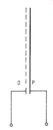
Fig. 1--Showing simple ESL arrangement.
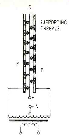
Fig. 2--Push-pull construction. PP are perforated metal plates (sometimes
curved) D is the diaphragm.
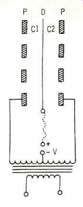
Fig. 3--Push-pull configuration with transformer.
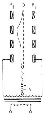
Fig. 4--Showing diaphragm displacement.
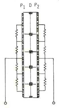
Fig. 5--Method of signal grading or distribution.
(adapted from Audio magazine, Mar 1971)
Also see:
Koss electrostatic speaker system (May 1977)
How to Add WOOFER to an Electrostatic Speaker (Mar. 1970)
= = = =