by Nelson Pass [Electrostatic Sound Systems, Inc. ]
To an engineer designing a loudspeaker system, one of the most important performance criteria is the transient response of the system. Good transient response requires that the speaker radiate sound as soon as a signal is applied, and stop radiating when the signal ends. The amount of time the speaker requires to reach 90% of its steady state amplitude for a given sinusoidal signal is called the attack time, and the time required to drop to 10% of that steady state amplitude can be called the decay time (Fig. 1). Since the attack time is primarily a function of the frequency response of the speaker and not very dependent on damping, we will be concerned with the effect of damping on the decay time. Obviously, for good transient response we want the decay time to be minimized. The speaker continues to radiate sound after the signal has ended because it has leftover energy--kinetic energy in the mass of the moving cone, potential energy stored in the speaker's suspension, and acoustic energy still bouncing around in the enclosure. To reduce the decay time it is necessary to drain off that leftover energy, and this is what damping does. Damping for loudspeakers is directly analogous to the use of shock absorbers in a car, which keep the suspension from oscillating after a bump. There are several ways to dampen the response of a loudspeaker-electrical, mechanical, and acoustical, and each has particular advantages and disadvantages.
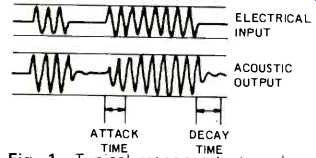
Fig. 1--Typical response to tone burst at 40 Hz.
Electrical damping works by letting the speaker behave as an electrical generator. Because the dynamic loudspeaker is essentially a motor, motion of its diaphragm can generate electrical currents. By draining off the energy in these electrical currents, we can reduce the decay time and help smooth out resonances in the loudspeaker and enclosure. For a simple demonstration of this technique, compare the resistance of a woofer to a light push on the cone when the terminals of the woofer are not connected to anything, and when the terminals are short-circuited. When the terminals are shorted, the cone becomes harder to move because the energy is being rapidly dissipated in the electrical circuit of the voice coil. The less resistance in that circuit, the more energy will be dissipated at a time. Damping factor, often quoted in amplifier specifications, is the ratio of the impedance of the voice coil of the loudspeaker to the output impedance of the amplifier. When the speaker is connected directly to an amplifier having a high damping factor, the speaker will be damped as if its terminals were shorted. An amplifier with a damping factor of 20 or greater will serve such a purpose, and because the limiting factor is the resistance of the voice coil, there is no significant difference in damping between an amplifier having a damping factor of 20 and one with a factor of 200. It should be remembered that to make use of the damping factor of the amplifier, cables should be as short as possible and coils in the crossover network should have as little resistance as possible. There are two other ways of increasing the damping beyond the limit set by the resistance of the voice coil. One is to increase the strength of the magnetic field in the voice coil gap, and another is to increase the amount of wire exposed to the magnetic field at one time in the voice coil. Both of these measures make the speaker a more efficient generator, allowing more energy to be drained off quickly. The energy is dissipated in the resistive elements of the circuit-mainly in the voice coil--as heat energy.
Electrical damping does have some disadvantages. It often requires the use of iron core coils in the crossover instead of air core coils, and unless properly designed they can become non-linear at high power levels.
Also, some loudspeaker systems depend on the woofer's fundamental resonance for boosted bass output, and as noted before, damping will reduce such response peaks, and also the overall efficiency of the speaker.
Mechanical damping occurs basically in two places in a loudspeaker, in the suspension and in the cone. Motion in the suspension dissipates some energy as heat, as demonstrated by the heating that occurs in a rubber band stretched rapidly several times.
This type of damping is occasionally found in midrange and high frequency speakers, where the suspension soaks up some of the energy and converts it to heat.
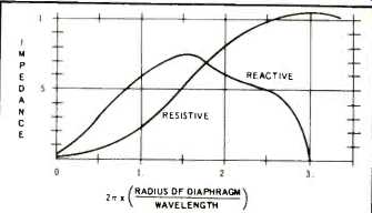
Fig. 2--Relative values of resistive impedance and reactive impedance for
diaphragm mounted in a large flat baffle.
Damping can also be found in the cone material itself, put there to dampen out vibrational modes occurring in the diaphragm. Often at higher frequencies, the cone ceases to behave as a piston and the motion varies over different parts of the cone. This can be valuable if the design of the speaker makes use of it, as in the decoupling rings found in some cones, but if the speaker was not designed that way, then the un-dampened vibrational modes will result in response irregularities due to phase cancellation and other factors.
Acoustic damping can be used to reduce resonances and decay time in a loudspeaker by increasing the resistivity and decreasing the reactance of the load of air the speaker is pushing against. If the acoustic load on the speaker is resistive, then the energy is efficiently dissipated into the air as sound. If the acoustic load is reactive, then the motion of the cone does little work-dissipating less unwanted energy and lowering the efficiency of the speaker. The impedance of the air for a given size diaphragm is dependent upon the frequency--as the frequency goes higher, the load becomes more resistive. If the cone size is increased, then the load will be more resistive at a given frequency (Fig. 2). When the diameter of the diaphragm is greater than 1/3 of the wavelength at a particular frequency, then the load starts becoming primarily resistive. As an example, the acoustic load on a twelve inch woofer is mostly resistive above 500 Hertz, but is very reactive below that frequency, and it becomes necessary to depend on other types of damping. Considering the need for a resistive load to reduce cone excursion and dampen response, it is easy to see why woofers must have large cones and why the speaker will have better bass output placed against a flat surface where the impedance is more resistive, but there are yet other ways to insure good acoustical damping.
Exponential and other types of horns can be used effectively to give a small speaker a resistive load down to a cutoff frequency determined by the flare rate of the horn and the size of the mouth (Fig. 3). A loudspeaker operating into a horn at a frequency higher than the cutoff frequency of the horn will experience good acoustic damping and high efficiency. It is also this high resistive load that allows horns to have very high acoustic output for very small excursion of the diaphragm, thus lowering the distortion caused by suspension non linearity. It is possible to reduce the necessary mouth area of a horn and still retain the resistive load through the use of resistive materials placed in the horn such as fiberglass or dacron.
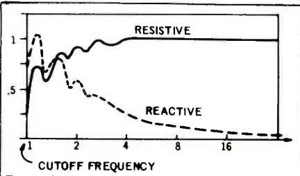
Fig. 3--Relative values of resistive and reactive load for speaker in an
exponential horn.
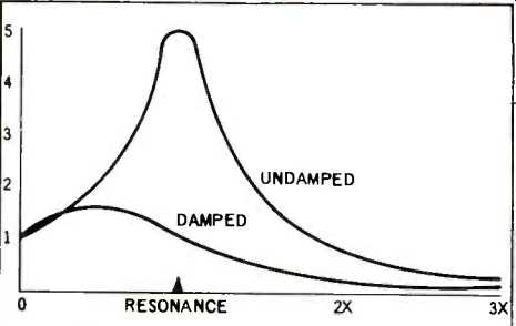
Fig. 4--Cone excursion at resonant frequency for two typical cases.
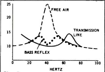
Fig. 5--Typical impedance curves for two enclosures.
Other types of enclosures have been designed to load down the speaker while increasing the acoustic output at the speaker's resonant frequency. At resonance, the speaker's undamped excursion becomes very large, causing harmonic distortion (Fig. 4). Enclosure designs such as the bass reflex or transmission line act to load down the speaker as resistively as possible at its resonance so that the acoustic output remains strong and the system is well damped while the cone excursion is nearly halved or more. The bass reflex accomplishes this loading by tuning the Helmholtz resonance of the enclosure to use the back wave off the rear of the diaphragm to boost the output off the front of the diaphragm at resonance. This loads down the woofer and works to dampen the spurious response at that frequency.
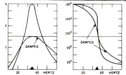
Fig. 6--A. Acoustic output of bass reflex port versus frequency. B. Phase
shift in output of port relative to directly radiated output.
A somewhat similar approach to acoustic damping is found in the transmission line, or acoustic labyrinth where a tubular pathway having a specific length guides the back wave until it comes out in phase with the front wave off the diaphragm. The tube is lined with a resistive material, and its length should be longer than 1/4 the wavelength of the speaker's resonant frequency.
The cone velocities reflect excursion in the speaker's impedance curve, and by examining the curve one can get an idea of the load on the woofer at resonance due to the action of the enclosure (Fig. 5). Additional resistive loading can be found in the use of fiberglass or dacron fiber in the port or duct of a bass reflex or placed tightly behind the diaphragm of the loudspeaker. The use of resistive material in the port of a bass reflex dampens out the enclosure resonance, smoothing the port output, and lowering the rate of phase shift of the output of the port (Fig. 6).
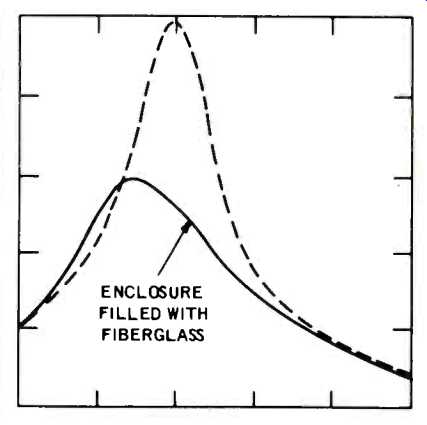
Fig. 7--Typical excursion of woofer at resonance in a sealed enclosure.
Still another type of acoustic damping exists where the interior of an enclosure is lined or stuffed with a resistive (absorptive) material to reduce the vibrational modes of the enclosure due to standing waves, the simplest of which consists of a sound bouncing back and forth between two parallel surfaces where the wavelength is equal to the distance between the surfaces divided by multiples of 1/2.
These vibrational modes must be damped out or they will cause response irregularities in the output of the speaker. In acoustic suspension or infinite baffle designs, the amount of stuffing is increased in the enclosure to make it behave as if it were 1.4 times larger in volume by slowing down the sound, so to speak. With that much acoustic resistance, the air compression becomes isothermal instead of adiabatic, and it dissipates much more energy, further dampening the system and lowering the resonance of the enclosure and speaker (Fig. 7). In designing a loudspeaker system, the amount of damping occurring both in the speakers and in the enclosure is an important factor which can only be tested properly by comparing tests of frequency response, transient response, distortion, and impedance against different amounts of electrical and acoustical damping. A peak in the response or impedance curves is indicative of an undamped resonance, but the most effective test is made with the use of tone bursts and waveform photographs. These quantitative methods will yield good results, but in the final analysis, the quality of sound as judged by listeners is the most important criterion.
-----------------
1. Leo L. Beranek, Acoustics, Chapter 2, McGraw-Hill, 1954.
2. C. R. Hanna and J. Slepian, "The Function and Design of Horns", Transactions A.1.E.E., presented Feb., 1924.
3. W. E. Glenn, "Terminated Horn Enclosures", I.R.E. Transactions on Audio. 1956.
------------
(adapted from Audio magazine, Mar. 1973)
Also see:
= = = =