Benjamin B. Bauer [CBS Laboratories, Stamford, CT ]
When stereo began its spectacular rise in popularity more than a dozen years ago I presented a paper before the Audio Engineering Society demonstrating that Stereophonic Perspective could be improved significantly, regardless of listener position by proper design of the directional characteristics of loudspeakers, and their placement with respect to the listening area. The improvement is explainable in terms of semi-directional polar patterns of conventional (e.g. "bookshelf-type") loudspeakers; it can further be enhanced with more strongly directional (e.g. "dipole" or "gradient") radiators'. A similar analytical and experimental process leads us to conclude that quadraphonic also benefits from properly positioned semi-directional and directional sound sources.
------
1. Broadening the Area of Stereophonic Perception" Tenth Annual Convention of the A.E.S., N.Y., Sept. 29, 1958.
2. B. B. Bauer, Jour. A.E.S., 8, 2, 91-94 (April 1960).
---------
What about the role of "omnidirectional" loudspeakers we hear so much about? It turns out that true omnidirectional radiation at all frequencies is difficult to achieve in practice; "semi-omnidirectional" performance, however, can be attained with relative ease. Omnidirectional loudspeakers obviously do not re quire directional orientation to cover a quadraphonic listening area reasonably well and, therefore, often are able to provide quadraphonic performance superior to that obtained with improperly oriented semi-directional loudspeakers; this is a very commendable attribute of systems intended for use by the lay public. On the other hand, omnidirectional loudspeakers can result in nasty wall reflection problems, and furthermore, any knowledgeable Hi-Fi enthusiast, or one who takes a bit of trouble to optimize loudspeaker placement, is apt to gain more satisfaction and improved quadraphonic performance with well designed semi directional loudspeakers; or, if he is fortunate enough to obtain them or skillful enough to devise them-with properly designed dipole units.
To provide a better understanding of the principles involved in applying directionality to quadraphonic loudspeaker arrays we discuss first the physics of omnidirectional or semi omnidirectional, semi-directional, and directional loudspeakers.
Omnidirectional Loudspeakers
At first blush, it would appear easy to design an omnidirectional loudspeaker; actually the task is rather formidable.
A truly omni-directional radiator is defined by a spherical surface which expands and contracts radially equally and in-phase. There are not many practical ways in which such a transducer can be fabricated. One approach is to use a hollow sphere (or two abutting hemispheres) of suitably polarized piezoelectric material (e.g. poly-crystalline lead zirconium titanate ceramic), including suitable internal and external electrodes to receive the electrical signals. Such a ball vibrates uniformly radiating equal amounts of sound intensity in all directions. Unfortunately such a transducer does not perform efficiently in air, (albeit it works fine underwater). To improve efficiency we can place a large number of small moving-coil loudspeakers on the surface of a sphere; but since the radiation characteristics of all the units must properly overlap, this approach turns out to be quite complex and expensive. Another possibility is to install a ring of small loudspeakers around a cylindrical drum, or even to place a single transducer on the end of the drum and to confront it with a reflector adapted to direct the medium and high-frequency sounds equally all around into the horizontal plane. Thus, from the truly omni-directional ceramic ball loudspeaker we progress in steps to various practical "semi-omnidirectional" designs which radiate sound relatively uniformly only in the horizontal plane.
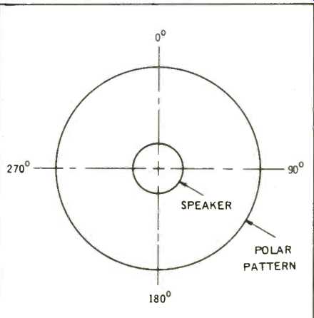
Fig. 1--Polar pattern of an omnidirectional speaker in free space.
Graphically we show this uniform radiation in Fig. 1 by a circular "polar pattern," which signifies that the sound pressure radiated at a given distance in a 360° compass is constant.
Next, we consider briefly what happens when an omnidirectional loudspeaker is placed near a reflecting wall or corner. In this circumstance its performance can best be analyzed by the method of virtual images. For example, in Fig. 2(a) the loudspeaker center is placed at 1 ft. from a reflecting wall. Because sound travels at a speed of 34,400 cm/sec, the wavelength at a low frequency, say 50 Hz, is 34,400/50 = 688 cm (22.6 ft.)--much greater than the distance between the loudspeaker and its image (2 ft.). Both the real and the virtual source may be assumed to radiate in-phase resulting in the doubling of sound pressure, with the polar radiation characteristic remaining nearly circular, as shown by the pattern labeled "50 Hz" in Fig. 2(a). In reality, real radiation is only outside the wall P shown in solid line. The virtual source and radiation being shown in dash-line. (The presence of this virtual source accounts for increased bass when a loudspeaker is placed near the wall). At higher frequencies, the wavelength lambda becomes comparable with the distance between the loudspeaker and its image, resulting in interference patterns. For example, at 282 Hz the distance is precisely 1/2 lambda resulting in total cancellation of radiation in a direction perpendicular to the wall, as shown by the polar pattern labeled "282 Hz." At other frequencies, different patterns will be generated. Placed in a corner, again at 1 ft. from both walls, as shown in Fig. 2(b), three virtual images are formed.
Again, at 50 Hz the pattern is nearly circular, and the radiated sound pressure is increased four-fold. At 282 Hz, the radiation near the walls drops to zero, but the radiation along the diagonal is a maximum, resulting in a rather narrow polar radiation pattern. Again, at other frequencies different patterns will be formed.
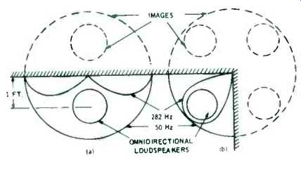
Fig. 2-Polar pattern of omnidirectional loudspeakers placed (a) near a wall
(b) near a corner.
Therefore, the response from an omnidirectional loudspeaker is rather unpredictable near reflecting walls or corners, suggesting that the presence of acoustical absorption on or near the walls may be desired to avoid the higher-frequency reflection modes.
Semi-Directional Loudspeakers
The majority of "bookshelf-type" and similar loudspeakers are semidirectional. This is to say, they are omnidirectional at low frequencies becoming relatively directional at high frequencies. This is illustrated by the way of example in Fig. 3 where at (a) is portrayed a loudspeaker consisting of a sealed box (popularly known as "infinite baffle") say 12 x 20 in. in cross-section, enclosing a driver with a piston width W = 8" or approximately 20 cm. In actual practice the piston is circular or elliptical; but to make our example as simple as possible we assume it to be rectangular with the long dimension perpendicular to the paper.
At a low frequency, say 50 Hz, where the wavelength is much greater than the dimensions of the box, the particles of air displaced by motions of the piston move to-and-fro together in imaginary channels-much like water flowing from an opening, as illustrated by the streamlines in Fig. 3(a). At a distance from the box, it becomes possible to strike a circular surface along which all the streamlines are distributed with a near equal density of flow, corresponding to equal sound pressure which expands in concentric circles away from the loudspeaker. Under this circumstance the loudspeaker behaves like an omnidirectional radiator.
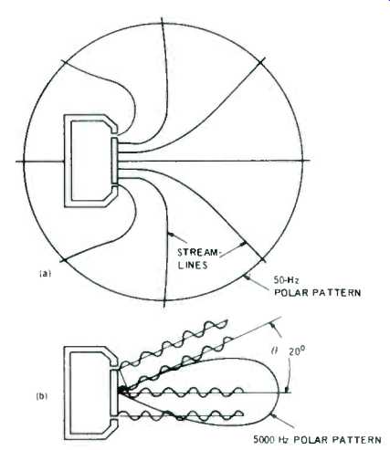
Fig. 3--Polar patterns for a piston in closed box for (a) low frequency
(50 Hz) and (b) moderately high frequency (5000 Hz).
As the frequency increases the wavelength becomes progressively shorter with the consequence that sounds from various portions of the piston are no longer in-phase causing the radiation off the principal axis to be diminished or even to become completely cancelled.
For example, consider the situation at 5000 Hz where lambda is but 34,400/5000 = 6.88 cm (2.7 in.). As may be seen in Fig. 3 (b), the wavelets from the center and edge of the piston in the direction parallel with the axis are in additive phase resulting in intense sound radiation forward of the piston; but at some angle, theta, the wavelets are found to be in phase-opposition causing complete cancellation. In the example given, theta is readily found as follows:
sin theta = (lambda/2)/( lambda /2) = lambda /W (1)
or, since lambda = 6.88 cm, and W = 20 cm, sin theta = 6.88/20 = 0.344; or theta = 20°.
From its on-axis maximum, the radiated sound pressure progressively diminishes to zero as shown by the polar-pattern in heavy line in 2(b). It is obvious that, in this last example, we are dealing with a narrow directional pattern which is unsuitable for high-quality sound reproduction at widely spaced positions in the room. To "broaden" the directional pattern sufficiently to obtain reasonably good coverage, we must restrict the upper frequency at which a piston is allowed to radiate. A workable rule of thumb for circular pistons is that the wavelength should not be less than the diameter of the piston. For an 8-inch piston this corresponds to 1720 Hz. To provide a satisfactory radiation pattern to 20,000 Hz the diameter of the piston should no exceed approximately 34,400/20,000 = 1.7 cm (0.68 in.).
At this point the reader might wonder why not use the small piston for all frequencies simply by making it work that much harder at low frequencies. This approach is counter-productive because the sound pressure generated at any given frequency at any point in space is related to the volume of air displaced by the motion of the piston, i.e. by its area multiplied by its linear vibration amplitude. Thus, an 8-inch diameter circular piston vibrating with a 1/4-inch motion is apt to provide adequate bass sound; a 1.7-cm diameter piston which has 1/22 the area of an 8-inch piston would have to have a 22-times longer stroke for the same sound output--or 5 1/2 in. which obviously is impractical.
Thus, the designer is caught between the limitations of maximum allowable piston amplitude, at one end of the frequency scale, with the directional radiation problems at the other, and he has to allocate the range covered by each piston to a relatively limited band of frequencies. This explains why a superior loudspeaker system usually will employ several drivers of different diameters interconnected electrically with dividing networks to convey to each its proper portion of the spectrum.
Typically, the response pattern of a good semi-directional loudspeaker is omnidirectional (circular) at low frequency narrowing-down to a 90°-60° included angle at about 1000 Hz and remaining within this range up to the highest frequency of interest, as various radiators of progressively smaller size come into play, as shown in Fig. 4. Because the baffle box diminishes the radiation toward the back at mid-frequencies, such a semidirectional loudspeaker is less bothered by reflections from the walls or corners, than an omnidirectional unit. Without pretense of offering a treatise on loudspeaker design, it should be noted that the polar pattern of a loudspeaker cone can be modified by shaping, adjusting compliance, adding acoustical lenses etc.
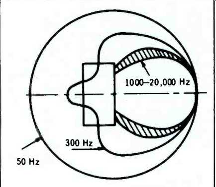
Fig. 4--Typical polar patterns for a conventional semi-directional (e.g.
bookshelf-type) loudspeaker at various frequencies.
Dipole Loudspeakers
A dipole loudspeaker is simply a piston (e.g. loudspeaker mechanism) vibrating in open air without an enclosure to confine the back radiation. The efficiency of such a device is a function of frequency because the radiations emerging from each side of the piston tend progressively to cancel each other as the wavelength increases.
Efficiency may be improved by adding to the piston a baffle, as shown in Fig. 5, which increases the distance between the front and the back of the piston. It is easy from Fig. 5 to visualize that, in the perpendicular front, or zero degree direction, the back sound radiation has to travel an added distance D before it can proceed to the front; the added distance giving rise to a phase differential between the two waves producing a net sound pressure at a given point in space designated as Po. As we move in a circle to the 90° direction, the radiations from both sides become equal and in antiphase; thus there is a zone of silence at all points on a surface S perpendicular to the axis.
As one travels to the back, or 180° direction, the distance D comes again into play (except that this time, from front-to-back) resulting in a maximum sound pressure at P_180. It is not difficult to prove mathematically that as one moves around the circle, the pressure function follows a cosine law, the polar pattern taking on the form of two circles at both sides of the piston. To avoid an excessive loss of efficiency the dimension of the baffle should be no less than approximately 1/6th the wavelength of the lowest frequency of interest. At high frequency the radiation from the piston narrows down in a manner similar to that described in Fig. 3. Therefore, the highest operating frequency for any one piston should be that corresponding to a wavelength equal to its dimensions. An 8-inch diameter loudspeaker installed in a 13-14 inch baffle, has a satisfactory operating range between 250 and 1700 Hz.
A second, correspondingly smaller gradient loudspeaker would be needed to cover a range between 1700 Hz and 10,000 Hz, etc. The polar pattern obtained with a composite gradient loudspeaker would then be approximated by the broadened circular outlines in Fig. 5.
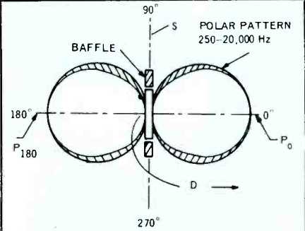
Fig. 5--Theoretical polar pattern of a dipole loudspeaker composed of progressively
smaller dipole elements to cover the full frequency range between 250-20,000
Hz. (Below 250 Hz, an omni-directional loudspeaker is used).
Experience has shown that response below 250 Hz can readily be provided with a conventional (omnidirectional) loudspeaker in an infinite baffle, without greatly influencing the aurally perceived directional characteristic of the gradient array.
Thus, a practical dipole loudspeaker generally is omnidirectional below about 250 Hz, and exhibits a figure eight pattern above 250 Hz, as shown by the heavy outline in Fig. 5. The frequency response of the combination must be carefully tailored to be "flat" overall. The biggest advantage offered by the dipole loudspeaker array is that it retains its cosine-law directional pattern over that portion of frequency which conveys the major part of directional information i.e. between 250 - 20,000 Hz.
A few dipole loudspeakers are available commercially. Usually they employ electrostatic high frequency sections and a moving coil bass section. For the present, however, the majority of high fidelity enthusiasts will have to be content with semi-directional loudspeakers to obtain the improved area coverage described below.
Application of Directional Loudspeaker to Stereophonic Arrays
The wrong and the right way of placing conventional semi-directional loudspeakers (e.g. bookshelf loudspeakers) for stereophonic listening is shown in Figs. 6 and 7, reproduced here from the paper referred to previously' with the kind permission of the Audio Engineering Society. In the first case, the loudspeakers are placed parallel to the front wall of the room. A listener at position P is at a greater distance from loudspeaker A than from the loudspeaker B. Also, the radiation strength of loudspeaker A in the direction P, represented by the vector AQ, is smaller than the radiation strength of loudspeaker B in the direction BP, as portrayed by the longer vector BR. Thus, the loudspeaker B has two advantages: The listener hears predominantly the sound of B and very little or no sound from the loudspeaker A. Furthermore, any sounds panned in between the two channels appear to move strongly towards B, because the Haas or "precedence" effect tends to credit the nearest loudspeaker with being the source of sound.
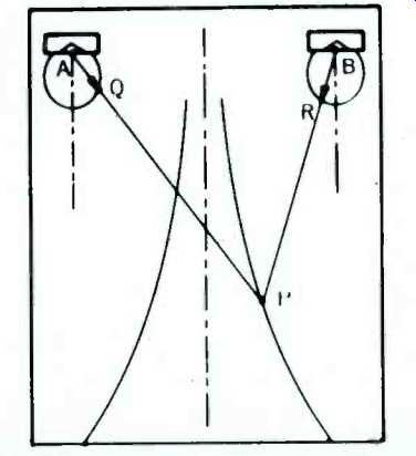
Fig. 6-Relatively narrow stereophonic listening area is obtained with directional
loudspeakers placed parallel to the wall (Courtesy AES.)
Next, we examine the operation of the improved placement method in Fig. 7. Here the listener at point P again is at a greater distance from A than from B. However, because the loudspeakers are at an appropriate angle with respect to each other and with respect to the listener at P, the radiation vector AQ in the direction AP is greater than the radiation vector BR in the direction BP. Thus, the distance effect is, in part, compensated by the directional effect. The sounds arriving from the two loudspeakers remain in balance over a considerably broader area than is possible with the arrangement in Fig. 6. Also, the added signal strength from the farthest loudspeaker tends, in part, to compensate for the Haas effect thereby allowing a significant amount of common sounds to appear in between the loudspeakers avoiding the so-called "hole in the middle" effect.
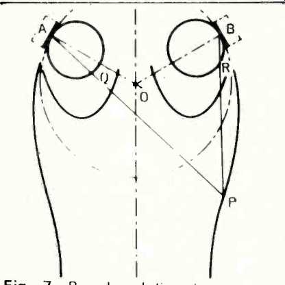
Fig. 7-Broadened listening area obtained with directional loudspeakers angled
towards the center (Courtesy AES. )
The solid line contours in Figs. 6 and 7 represent the listening area within which the signal strengths from loudspeakers having radiation pattern as described remain within 3 dB of balance relative to each other. The advantage of the inclined orientation is evident. For an average bookshelf-type loudspeaker, the included angle between the loudspeaker axes, for proper orientation, turns out to be approximately 120-130 degrees.
Wall Reflections with Dipole Loudspeakers
We have shown, in a previous section, that omnidirectional loudspeakers under certain circumstances are significantly affected by reflections from the walls. Dipole loudspeakers, by contrast, are relatively free of this problem.
It has been seen from one of the preceding sections that directional loudspeakers normally are placed at an angle to the walls enclosing the listening area. Fig. 8(a) represents the polar pattern of a dipole loudspeaker placed, say, at 45° to a wall. It will be noted that a listener at P is subjected to its maximum output. This same listener is in a near-null orientation with respect to the virtual image caused by wall reflection. Furthermore, with the dipole loudspeaker placed in a corner, as shown in Fig. 8(b), two of three virtual images are oriented with the null planes toward the listener, thus contributing relatively little to the sound pressure at P. Thus, the response characteristic produced by a dipole loudspeaker is apt to be less affected by room acoustics than that produced by an omnidirectional unit. It should be noted, however, that the "back" radiation of the gradient loudspeaker does exist, and while it may not be significant on first reflection, it may become so for subsequent, later, reflections helping to create a desirable "ambiance" effect.
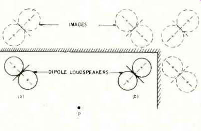
Fig. 8--Angled dipole units (a) near wall and (b) near corner.
Quadraphonic Arrays
Following the example given previously in connection with stereophonic arrays, the benefits of directional loudspeakers in quadraphonic listening will now be demonstrated. Fig. 9 portrays a quadraphonic listening area with 4 omnidirectional loudspeakers placed in the corners. For the sake of simplicity we assume for the moment that there are no walls to cause directional cancellation and reinforcement problems. Thus, the polar patterns of the loudspeakers are shown as four circles concentric with the corners of the listening area (which forms a dash-line perimeter). That portion of the listening area where the sound pressure from any of the four loudspeakers varies no more than ± 3 dB is shown by the diamond-shaped outline.
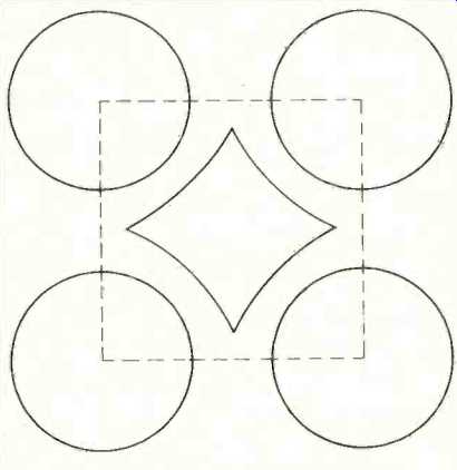
Fig. 9--Quadraphonic listening area with four omnidirectional loudspeakers
placed in the corners.
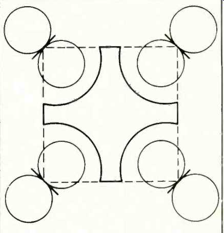
Fig.
10--Quadraphonic listening area with four dipole loudspeakers.
In Fig. 10, dipole loudspeakers are used. The +/-3 dB contour is now increased substantially, reaching all the way to the edge of the square; thus greatly increasing the positional freedom of the listeners. Similar, but perhaps not quite as dramatic improvement is obtained with semi-directional loudspeakers in the corners facing the center of the area. On the other hand, if these semi-directional loudspeakers were to be placed squarely against a wall (instead of being angled), their directional patterns would tend to augment the effect of the inverse distance law causing the optimum listening area further to be restricted.
The aforementioned analysis holds true even in conventional semi-reverberant listening rooms because directional localization depends principally on the sounds of first arrival.
Conclusion
Much remains to be learned about optimum design and placement of quadraphonic loudspeaker arrays. Omnidirectional loudspeakers in vogue today are a partial answer to this problem--albeit one troubled by excessive dependence upon the acoustical characteristics of the room boundaries. Also, omnidirectional loudspeakers produce a relatively limited area of quadraphonic perception. Directional loudspeakers--e.g. semi-directional or "bookshelf" types, and especially the dipole types, are apt to result in a more balanced sound field over a broader listening area, but usually require some experimentation with orientation and seating arrangements.
(adapted from Audio magazine, Mar. 1973)
Also see:
In All Directions by John Crabbe (Mar. 1973)
Omnidirectional Radiation (in Acoustics) (Mar. 1973)
The Loudspeaker as a Spherical Sound Source (Mar. 1973)
= = = =