
MANUFACTURER'S SPECIFICATIONS:
Frequency Response: 1 Hz to 100 kHz ±0.5 dB.
Phase Response: ±8°, 20 Hz to 20 kHz.
THD (29 Hz to 20 kHz): Less than 0.0008 percent at 2.5 V (rated) output; less than 0.0025 percent at 10 V output.
IMD: Less than 0.0003 percent up to 10 V output.
S/N Ratio, "A" Weighted: From 101 dB (at maximum gain) to 118 dB (minimum gain) below rated output.
Maximum Output: 11 volts (22 V in balanced mode).
Maximum Headphone Output Level: 17 V rms.
Headphone Output Frequency Response: 10 Hz to 50 kHz, ±0.1 dB.
Bass Control Range: ±15 dB at 20, 40, or 80 Hz.
Midrange Control & Range: ±15 dB at 400, 800, or 1600 Hz.
Treble Control Range: ±15 dB at 5, 10, or 20 kHz.
Low-Cut Filters: -3 dB at 20, 30, 50, or 100 Hz, 18 dB/octave.
High-Cut Filters: -3 dB at 4, 7, 12, or 20 kHz, 18 dB/octave.
Phono Module Section:
Frequency Response (10-kilohm Load): RIAA, ±0.25 dB, 20 Hz to 20 kHz.
Flat Position: 10 Hz to 30 kHz, ±0.1 dB.
Phase Response: ±5°, 20 Hz to 20 kHz (in RIAA).
THD: Less than 0.002 percent at 2.5 V out, 20 Hz to 20 kHz.
IMD: Less Than 0.0005 percent at 2.5 V out in flat position.
S/N Ratio: 94 dB in RIAA, 89 dB in flat position re: 10 mV, "A" weighted.
Gain: Adjustable from 30 to 50 dB, 0.75 mV input for rated output at maximum gain.
Input Overload: 100 mV at 40 dB gain (varies from 33 to 330 mV depending upon gain setting).
Input Impedance: 47k/100k selectable, parallel C less than 5 pF.
Power Supply Module:
A.C. Outlets: Seven switched and two unswitched.
D.C. Outputs: ±28 V at 500 mA, ±18 V at 500 mA; +10 V at 2 amps.
General Specifications
Dimensions: Control Module, front panel fits 19-in. rack; chassis behind front panel; 17 in. (43.2 cm) W x 71 in. (19 cm) H x 14 in. (35.6 cm) D.
Power Supply Module (fits 19-in. rack); 17 in. (43.2 cm) W x 31 in. (8.9 cm) H x 71 in. (19 cm) D.
Power Requirements: Less than 40 W at 120 V a.c.
Price: $1995.00.


To begin with, let me say that when I was confronted with the published specifications of this magnificent, three-piece preamplifier/control system I had to completely rethink my laboratory test procedures. Normally, I like to measure the equipment on the bench first to confirm published specs and only when I am satisfied with these do I subject a given piece of equipment to extensive listening tests and use evaluation.
In the case of the Crown DL-2 system, I must confess that the unit was on the bench for less than an hour. No way was I able to measure the distortion of either the control module section or the phono module section. The residual distortion and noise levels of my test equipment are just not up to the job. The brief time devoted to measurement was more than offset by the overly long use tests to which I subjected this equipment. The DL-2 is so feature-laden that no report of this restricted length could possibly cover all its features. Still, let's try.
Turning our attention first to the control module's front panel we find 8 light-touch buttons at the upper left. The upper two are for power switching and audio muting, six are labeled tape and AUX (three each), and the remaining two are called Phono arid Tuner. Actually, all of these buttons control identical high-level inputs (since the phono module is connected separately), and it is up to the user to assign buttons to appropriate input sources. The labels can be switched around from button to button and a light next to each button glows when that particular input is chosen. The buttons simply supply d.c. switching voltage to the control logic circuitry which activates reed-relays that do the actual selection.
Six vertical sliders at the right of the panel, calibrated in 2- or 3-dB steps, operate the bass, midrange, and treble tone control circuitry (separately for each channel). The center frequency of each tone control can be changed to any of three frequencies by means of slide switches below each slider.
Perhaps the most intriguing control element of the DL-2 is its gain control arrangement. Six buttons at the center of the panel are used to alter gain. Two buttons at the center, when touched, raise or lower gain in both channels simultaneously by exactly 0.5 dB increments, over a total range of 63.5 dB, while pairs of buttons to the left and right of these control individual channel gain in the same manner. Gain of each channel is displayed on three-digit, seven-segment numerical displays. The displays operate at full brilliance during the Operate Mode and at reduced brilliance during Standby. At a reading of 43.5 dB actual gain of the module is unity. The gain buttons are speed conscious, operating slowly when first depressed but increasing the speed of gain increments if held in the depressed mode. If gain is raised to beyond clipping level of any input signal, two peak indicators below the gain buttons glow to warn the user to reduce gain.
A separate loudness contour control, located below the gain buttons, reduces gain in precise 5-dB increments as it is rotated clockwise, over a total range of 50 dB. This control is calibrated in "phons." Additional pushbuttons to the left and right of the loudness knob activate tone controls, high- and low-cut filters, permit insertion of up to two signal processors (such as expanders, equalizers, noise reduction systems, etc.), and insert these processors either ahead of or after the tape recording output.
Tape 3 in/out jacks are located at the lower left of the panel, and near them is a tape-copy switch (which permits direct copying from one tape recorder to two others), three tape monitor buttons, signal-processor locating switch (either before or after tape outputs), high- and low-cut frequency selection switches, a pair of main-output selector switches, two phone jacks, and three controls collectively identified as audio imaging controls. Each of these controls is a concentric pair of knobs that can be used to vary the pro portions of the two input channels that appear in the two output channels. Each control has 32 discrete switched settings, using precision resistors, including a full "off" position. The first imaging control sends signals from A and B inputs (program source inputs) to left and right outputs. The second set of controls sends A signals to the right and B signals to the left output. The third pair controls two different pairs of inputs. Since all of these controls are nearly continuously variable, the audio imaging possibilities are almost limitless, providing the DL-2 with the flexibility of a small mixer and panning control system.
The rear panel of the DL-2 Control Module contains the five sets of input jacks, three tape in and out pairs of jacks, two pairs of external signal processor input and output jacks, the extra "cross-feed" inputs for the mixing function de scribed in connection with the stereo imaging controls, buffered outputs, and several main outputs including stereo and mono, normal and inverted.
In addition, the rear panel contains a multiple-pin connector to which the power cable is connected from the separate power module of the D1-2, plus a pair of other connectors which are intended for connection to a home computer which, presumably, could be programmed to control level power, and input selection. Crown advises that the capability of the DL-2 is, in fact, checked by means of a computer.
The separate "Phono Module" supplied as part of the DL-2 system is also connected to the power supply module by means of a supplied cable. It is intended, however, to be located as close as possible to the turntable system with which it is used so as to minimize possible hum pickup. The module may be operated as a "flat amp" (without equalization) or with RIAA equalization, and its gain is variable and can be set separately for each channel (in case cartridges provide unequal left and right signals) over a range from 30 to 50 dB. Normally, one sets the gain for 40 dB. The particular module supplied with our test unit is known as Phono Module A, and another Module (B) will soon be available for use with moving-coil cartridges.
The separate Power Module of the DL-2 has a power indicator light and a single pushbutton switch. During normal operation, the power module is left turned on at all times, remaining in "standby" mode until one of the input selector buttons on the Control Module is touched. This activates the a.c. switched receptacles on the Power Module and powers the Control Module. At the same time, digital display of gain increases in brightness.
Touching the power button on the Control Module returns the system to "standby" mode. Though the suggested price of the system is given as $1995.00, individual prices for the separate sections of the unit are $1450.00 for the control module, and $250.00 each for the power supply and phono modules. Presumably, one could operate more than one phono module off the same power supply module by means of an available Y-connector and could simply re-label an additional input button accordingly.
Laboratory Measurements
Any attempt on our part to measure distortion levels of either the control module or the phono module of the DL-2 was rewarded by utter frustration. The residual distortion levels of our Sound Technology audio generator and distortion measurement system (around 0.002 percent) were the governing factors here. We were, however, able to measure a few operating characteristics of the unit. RIAA equalization of the phono module was found to be accurate to within ±0.1 dB from 20 Hz to 20 kHz and the phono inputs required a signal level of 8.5 millivolts for 2.5 volts rated output. With gain set for IHF reference levels (0.5 volts out for 5 mV in), overload occurred with an input of 100 mV at 1 kHz. Noise level from this module was below our measuring capabilities! Frequency response of the DL-2 Control Module high level inputs was flat to within 1.0 dB from below 5 Hz to 150 kHz, with the-3 dB roll-off occurring at 230 kHz.
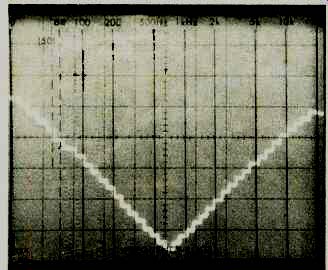
Fig. 1--Action of precision 0.5 dB/step attenuator system.

Fig. 2--Bass, midrange, and treble controls have selectable center frequencies
as well as boost and cut capability of ±15 dB.

Fig. 3--Four position high-and low-cut filters provide cut-off slopes of
18 dB/octave.

Fig. 4--Separate loudness control is calibrated in precise 5-dB steps.
Figure 1 illustrates the precise action of the gain control "steps." In this 'scope photo, our spectrum analyzer was tuned to a single frequency (that being applied to the DL-2), so the frequency notations at the top of the display should be ignored. We then allowed the 'scope beam to sweep slowly across the face of the CRT to display only amplitude, as we tapped the gain control successively downward and then upward. The vertical sensitivity of the scope was set to 2 dB per vertical division and, as you can see, four steps of our descending and rising "staircase" occupy exactly one division, confirming the 0.5 dB per step accuracy of the novel gain control system of the DL-2.
Figure 2 illustrates the versatility of the tone control system of the D1-2. Shown are a composite of the low, mid and treble controls, each operated at maximum boost or cut and at their three available center frequencies. The resulting display shows that the tone control system has two of the three degrees of versatility of a parametric equalizer (variation of bandwidth is not possible). (Sensitivity of the 'scope is now 10 dB per division.) Action of the four-position high- and low-cut filters is plot ted in the 'scope photo of Fig. 3. Have you ever encountered such precision filtering in a home consumer preamplifier? We haven't! Finally, in Fig. 4 we show the action of the loudness-con tour control as it is rotated in 5-dB steps clockwise from highest gain to its lowest setting. A few other preamplifiers we have tested do provide separate loudness control function (in addition to the master volume control), and we consider this to be the only kind of loudness control arrangement that can hope to provide proper loudness compensation. But rarely have we seen one so precisely calibrated as this one supplied on the DL-2.
Listening and Use Tests
It almost goes without saying that the sound reproduction capability of the DL-2 is limited only by the quality of the program source being fed into it. As we all know, the actual static distortion levels are so low that they cannot contribute any perceivable differences between the original and reproduced signals. But even those for-the-moment intangible forms of distortion we all talk about (but can't agree on how to measure, such as TIM) were totally absent from the sound reproduced via the DL-2.
But an evaluation of the merits of the DL-2 goes far be yond an appraisal of the way in which it delivers signals to an associated power amplifier and a pair of loudspeaker systems. We must address ourselves to the question of who might be the ultimate user of this equipment. Is it the super-audiophile who demands the kind of "straight wire with gain" sound of which this unit is capable and nothing more? That doesn't seem very likely, since that individual is often "turned off" by expensive control features, many of which contribute little to ultimate sound quality.
More likely, the unit will find favor with the audiophile who is also a serious recordist. Probably, the potential buyer of the DL-2 owns more than one open-reel or cassette tape deck, plus a variety of add-ons and signal processors, all of which can interface nicely with the DL-2 and can be con trolled from its front panel in masterly fashion. Nor should we overlook the audio enthusiast who, when confronted with the awesome control capability of the DL-2, will simply fall in love with it, much as a child falls in love with an irresistible toy. For the computer fan who also happens to be an audio devotee, the possibilities are endless. Frankly, if my own funds were less limited, I would opt for a control unit such as this, for the sheer delight one experiences in using it, but unfortunately, my funds are not that unlimited. Sigh!
-Leonard Feldman
(Audio magazine, Mar. 1979)
Also see:
Crown Model FM-1 Stereo FM Tuner (May 1980)
= = = =