MANUFACTURER’S SPECIFICATIONS:
a/d/s/ CC4 Tuner/Preamp
Manufacturer's Specifications:
FM Tuner Section:
Usable Sensitivity: 14.8 dBf.
50-dB Quieting Sensitivity: Mono, 27 dBf; stereo, 40 dBf.
S/N: Mono, 70 dB; stereo, 65 dB.
THD at 1 kHz: Mono, 0.1%; stereo, 0.15%.
Frequency Response: 20 Hz to 15 kHz, +0,-1.0 dB.
Separation: 47 dB at 1 kHz; greater than 30 dB, 30 Hz to 15 kHz.
Capture Ratio: 2.0 dB.
Alternate-Channel Selectivity: 65 dB.
Muting and Stereo Threshold: 27 dBf.
I.F. Rejection: 100 dB. Image Rejection: 95 dB.
Spurious-Response Rejection: 100 dB.
AM Rejection: 50 dB.
Subcarrier Rejection: 65 dB.
AM Tuner Section:
Sensitivity for S/N of 6 dB: 8 µV
Image Rejection: 35 dB.
Preamplifier Section:
Rated Output Level: More than 3 V rms at no more than 0.07% THD.
Frequency Response: Phono, RIAA, 20 Hz to 20 kHz, ±0.5 dB; high level, 20 Hz to 20 kHz, + 0, -0.5 dB.
IHF Input Sensitivity: MM phono, 1.3 mV; MC phone, 130 µV; high level, 90 mV.
IHF S/N: MM phono, 70 dB; MC phono, 65 dB; high level, 80 dB.
IHF Maximum Input Level: MM phono, 150 mV; MC phono, 15 mV; high level, 5 V.
Rise-Time: High-level inputs, 1.5 µS.
Treble Control Range: ± 10 dB at 20 kHz in 2-dB steps.
Bass Control Range: ± 10 dB at 20 Hz in 2-dB steps.
Low Bass Control Range: +6 dB at 20 Hz in 1-dB steps.
20-Hz Control (Subsonic Filter): -12 dB per octave below 20 Hz.
Input/Output Polarity: Non-inverting.
General Specifications:
Power Requirements: 120 V a.c., 60 Hz, 50 watts.
Dimensions: 17 1/2 in. W x 2 3/4 in. H x 14 1/4 in. D (44.5 cm x 7 cm x 37.8 cm).
Weight: 15 lbs. (7 kg).
Price: $1,000.
Company Address: One Progress Way, Wilmington, Mass. 01887, USA.
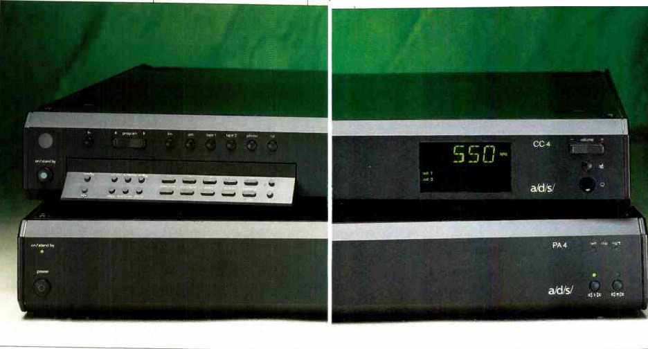
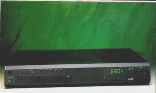
The CC4 tuner/preamplifier is part of the a/d/s/ Atelier series of interactive audio components. Having explored its many features and control functions, I can state that it is by far one of the most sophisticated control centers I have yet come across. The CC4's operating system is based on an internal computer that controls a wide variety of functions, such as input-sensitivity programming, 30-station AM and FM memory, all-electronic volume and balance controls, and much more.
All other Atelier components, when connected to the CC4, can be integrated into a remotely operable multi-room system. The control diversity afforded if you purchase an optional a/d/s/ RC1 wireless remote ($150) has several unusual aspects. Two cassette decks are fully controlled, and an automatic video input can turn the CC4 on when audio signals from a TV are present at the video input jacks.
In my own tests, I used the CC4 only with the a/d/s/ PA4 power amplifier.
These two components are so closely linked in function and so well matched in design that they form, in effect, an integrated amp. I did not have an RC1 remote, but judging by the excellent design of the CC4 and its matching amp, I have no reason to doubt the effectiveness of any of the more sophisticated control features described in the well-written owner's manual.
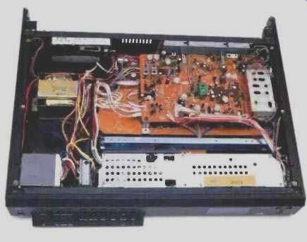
Internally, all preamp circuits are fully shielded, and all inputs are buffered by filtered amplifiers for good r.f.i. suppression and uniform input impedance. All of the tone, filter, and level controls are electronically operated by internal computer commands. Results are therefore very precise and repeatable. The alphanumeric display provides complete operational status information. Among the items shown are: Source selected for listening and recording, station frequency and program memory number (during use of FM or AM), and volume, balance, and tone control settings (in dB). The FM tuner section of the CC4 uses a temperature-compensated, varactor-tuned front-end. The stereo decoder circuitry employs both pilot subcarrier cancellation and analog tuned filters for subcarrier product rejection. A high-blend circuit can be selected in FM mode to improve S/N ratios of weak FM stereo signals. If this setting is stored along with the station frequency, the high-blend function will automatically turn on when the station is selected by memory recall. Since the CC4 can be manually tuned in frequency increments of as little as 25 kHz, it is possible to improve reception of some stations when interference from other signals, close in frequency to the desired signal, occur. This feature may also be useful when receiving FM stations via cable, since many cable companies that carry FM shift the stations to nonstandard broadcast frequencies.
The two sets of preamp outputs can feed one or more amplifiers and can be independently switched on and off from the CC4's front panel, while speaker switching for the connected PA4 power amplifiers can be controlled from the optional RC1 remote.
Control Layout
The CC4 front panel has, in effect, two tiers of controls.
The major tier, visible at all times, starts at the far left with buttons for power-on/standby and "TV," a "Program" rocker switch that moves forward or backward through the 30 programmable AM or FM station memories, and selector buttons for FM, AM, two tape monitors, phono, and CD. At the far right are a volume up/down rocker and a mute button. Beneath the mute button is a stereo headphone jack. The "TV" button selects both listening and recording of TV sound if a TV monitor's audio outputs are connected to the system. Holding this button down for more than 3 S puts the CC4 in the TV "auto" mode. In this mode, the CC4 turns on automatically whenever it senses the presence of audio signals at the TV input jacks. Volume is automatically set to "65" (15 dB below maximum), and all tone controls and filters are turned off, yielding further control to the TV monitor itself. This mode is disabled by holding down the "TV" button for another 3S.
The multi-functional display, near the right end of the front panel, has lighted labels that show when various functions are active, such as tone control and speaker selection.
There are two sets of alphanumeric displays. In general, the upper display shows the selected signal source, while the lower one shows information concerning that source. When the tuner section is in use, the upper display shows selected frequency, while the lower shows the program memory number, if any. (Incidentally, the 30 program memories can be used to randomly store both AM and FM stations.) Additional illuminated words in the display area show which of the two output pairs is in use, whether a stereo signal is being received, if the CC4 has been switched to mono or high blend, whether the "low bass" boost mode has been selected, and the status of the bass and treble controls.
The second tier of controls is accessed by pushing a tilt-down panel that smoothly emerges from the unit's front and comes to rest at an angle that makes for easy viewing and use. It contains buttons for up and down manual or automatic tuning of the FM and AM sections, "+" and "-" bass and treble controls, "Left" and "Right" buttons for adjusting channel balance. preamp "Out 1" and "Out 2" selectors, and buttons for loudness, high blend, low bass boost, 20-Hz filter, mono, and "Copy," as well as a "Memo" button for memorizing favorite AM and FM station frequencies.
"Memo" performs an important additional function: It can be used to adjust the input sensitivity for all program sources so that they will all have the same apparent sound level when selected. This adjustment can be made over a range of 10 dB in steps of 1 dB. The "Copy" button, if pressed once, sets up tape dubbing from "Tape 1" to "Tape 2." Pressing "Copy" a second time reverses the direction of the dubbing process. While you're in copy mode, you can listen to any one of seven program sources, including the decks being used for dubbing. Pressing "Copy" a third time turns off the copy mode and restores the original condition; the recording source is then the same as the listening source.
During use of the "Copy" control, the upper display shows the listening source first, followed by the recording source--for example, "FM", "T1" (for tape 1). Finally, this subpanel contains what a/d/s/ refers to as a "direct" switch. When this button is pressed, bass, treble, loudness, "Low Bass," and "20 Hz" controls turn off to produce flat response once again, and the balance control is restored to its center setting. Pressing the "direct" button a second time restores all previous settings of the above-named controls. I found that this made for a very convenient way of comparing electrically "flat" reproduction with my settings of the various controls.
In addition to the usual assortment of stereo input and output jacks, 75- and 300-ohm FM antenna input terminals, AM antenna terminals, and a slide switch that selects moving-magnet or moving-coil phono inputs, the rear panel is equipped with six multiple-pin DIN connectors. The ones labeled "Phono," "Tape 1," and "Tape 2" send translated remote-control signals to the appropriate a/d/s/ Atelier remote-ready components. The "Master 1" DIN connector accepts remote-control signals from a separate infrared receiver unit, thereby extending remote operation of an Atelier audio system to rooms other than the one where the components are located. This jack also enables connection to a personal computer, using RS-232 signal protocol. The "Master 2" DIN connector parallels "Master 1," for looping through transmissions to an aid/s/ Compact Disc player or other unit. The sixth DIN connector, labeled "Speaker Remote," sends power on/off and speaker-selector signals to a/d/s/ Atelier power amplifiers such as the PA4, which I used with the CC4 in my listening tests. Finally, there are a total of six a.c. convenience outlets, four switched and two unswitched. These can provide up to 800 watts of power to other audio components whose line cords are connected to the CC4.
Tuner Measurements
Frequency response of the FM tuner section is plotted for both channels in Fig. 1. Response was down by slightly more than 1.0 d8 at 15 kHz. Figure 2 shows the quieting characteristics of the FM tuner section. In mono, 50-dB quieting required a signal input of 13 dBf; in stereo, a signal strength of 39 dBf produced the same degree of quieting.
Note that at signal levels below 30 dBf, reception begins reverting to mono. In tact, this transition occurred at precisely 27 dBf, as claimed by a/d/s/. However, because the plotted points were done at 30 and 20 dBf, with no automatically plotted points in between, it appears as though the transition occurred at 30 dBf. Maximum quieting for mono at high signal levels measured 75 dB, while maximum stereo quieting was 72.5 dB. Both of these figures are well above the S/N figures specified by a/d/s/. Figure 3 shows how THD + N varied as a function of signal strength. This graph also pinpoints the usable sensitivity in mono. It is the point at which THD + N amounts to no more than 3%, and for this sample, that occurred at an input signal level of 13 dBf. Lowest mono THD + N fell a bit short of the claimed 0.1%, measuring 0.125% at 65 dBf. In stereo, however, THD + N was actually lower than claimed by a/d/s/ and, at strong signal levels, was even lower than the mono THD + N figure. At 65 dBf, stereo THD + N was only 0.076%, as against 0.15% specified by a/d/s/. Figure 4 is a plot of THD + N versus audio modulating frequency from 50 Hz to 15 kHz, for mono and stereo. using a constant 100% modulating signal. There is good correlation between the data recorded in Figs. 3 and 4 for mono, but the stereo THD + N appears to be a bit higher at 1 kHz than the figure I obtained earlier. This is because Fig. 4 is plotted automatically, giving me no opportunity to retune manually between the mono and stereo sweeps. As a result, the tuning was optimized for mono reception but was not quite as precise for the stereo readings. Even a slight amount of detuning can change an FM tuner's THD readings by significant amounts. In this case, the difference was actually very slight; in fact, the THD + N readings at 1 kHz were almost identical for mono and stereo, or slightly higher than 0.1%.
Figure 5 depicts results of a spectrum analysis sweep of the outputs of the CC4 when the FM section was reproducing a 5-kHz signal, modulating just one channel while in the stereo mode. Two sweeps were made. The first produced the tall spike at the left, representing the desired output from the modulated channel. The second sweep was made while measuring the output of the unmodulated channel. Since vertical calibration was 10 dB per division, this sweep shows that separation at 5 kHz was about 45 dB (the short spike within the tall spike). The sweep extended linearly to 50 kHz, and you can see that crossover components in the unmodulated channel's outputs consisted of some harmonic distortion, some spurious components produced by "beats," and some output at the subcarrier frequency of 19 kHz. This subcarrier component was about-60 dB compared with the 100% modulation level.
Figure 6 shows how FM stereo separation varied as a function of audio frequency. The upper solid curve shows response at the output of the modulated channel, and the lower dashed curve shows separation under normal operating conditions, without the use of the high-blend feature.
Under these conditions, separation measured 48 dB at 1 kHz, 42.7 dB at 50 Hz, and about 42 dB at 15 kHz. The results at the frequency extremes are far better than the minimum separation values claimed by the manufacturer. At 100 Hz and 10 kHz (the frequencies at which separation is supposed to be stated if specs are to conform with the IHF/EIA Measurement Standard), separation was 45.5 and 46 dB, respectively.
The upper dashed curve in Fig. 6 shows what happens when the high-blend circuit is activated to improve weak signal stereo reception. Under these conditions, separation at low frequencies remained relatively high. At 1 kHz, however, separation decreased to just over 18 dB with respect to the lower solid curve, which represents the output at the desired channel during this second test sweep. At 10 kHz separation was only around 7 dB. Several additional measurements of FM performance that didn't require graphic plots were also made during my evaluation of the CC4's tuner section. Capture ratio was 1.8 dB, a bit better than the claimed 2.0 dB. AM rejection was 52 dB, while i.f., image, and spurious-response rejection were all in excess of 100 dB, the limits of my measuring capability for these tests. Alternate-channel selectivity ranged from a low of 65 dB to a high of 70 dB, depending on the radio frequencies used.
I spent only a short time evaluating the AM tuner section, but I did plot frequency response (Fig. 7). As is traditional in AM response measurements, I looked for the-6 dB roll-off points rather than the-3 dB or even-1 dB points normally used to describe the bandwidths of high-fidelity equipment.
Even for this more relaxed response measurement, I found that the CC4's AM bandwidth extended only from 42 Hz to 3 kHz. It was pretty clear from this result that most of the a/d/s/ tuner design effort was concentrated on the component's FM section!
Preamplifier Measurements
Frequency response for the high-level inputs of the CC4's preamplifier section was flat within +0.1 dB and -0.2 dB from 20 Hz to 20 kHz. The response was plotted for one channel only (Fig. 8), since both channels exhibited identical response curves. Multiple sweeps were made to create the curves of Fig. 9. I simply adjusted bass and treble controls to minimum and maximum settings, plotting a new response curve after each adjustment was made. The typical "bow tie" pattern of Fig. 9 is about what would expect from any well-designed tone control circuitry. What did surprise me just a bit was the shift in level at low frequencies when the treble control was set to its maximum cut position.
This shift, noticeable from around 600 Hz downward, amounted to nearly 2 dB. By contrast, hardly any shift of level for nonequalized segments of the spectrum was observed at maximum treble boost or at maximum cut or boost of the bass control.
I was very pleased to note that the loudness compensation built into this unit affected only the bass frequencies.
That's all a loudness control should do, as I've pointed out more than once. Furthermore, the action was gradual, increasing the amount of boost as the master volume was adjusted to lower and lower settings. Response sweeps at maximum volume,-10,-20,-30,-40, and-50 dB settings are shown in Fig. 10.
Figure 11 shows how THD + N varied as a function of output voltage for the high-level inputs, using a 1-kHz input signal. At 3 V out (the output level specified by a/d/s/), THD+ N was only 0.004%. Maximum output before serious distortion occurred was 9 V rms. With my test equipment adjusting input level to produce a constant 3 V output from the CC4, I next plotted THD + N as a function of input frequency (Fig. 12). The higher distortion at 1 kHz observed this time (0.019%) resulted from my using a higher input voltage and lowering the volume control to keep the output at 3 V. In any case, for all but the lowest frequencies, THD+ N was still under 0.02% and reached a level of 0.08% at 20 Hz. Using these same volume-control and input-level settings, I plotted SMPTE-IM distortion versus output level, using the standard 4:1 ratio of 60-Hz and 7-kHz signals as my input (Fig. 13). At an equivalent output of 3 V rms, SMPTE IM was only 0.033%, while maximum output before serious overload occurred was equivalent to about 7.3 V. Sensitivity for the high-level inputs, measured in accordance with IHF/EIA Standards, was 77.8 mV-less than specified. For the high-level inputs, S/N, using a 0.5-V input and adjusting the output to 0.5 V, was a very high 92.18 dBA for the left channel and 92.37 dBA for the right.
Turning to the phono preamplifier section, I measured sensitivity for the MM inputs of 1.08 mV for an output of 0.5 V, while S/N for these inputs measured 78.71 dB for both channels. Figure 14 shows deviation from perfect RIAA playback equalization. At 20 Hz, this deviation was only
0.2 dB, while at 15 kHz, deviation amounted to approximately +0.4 dB. MM phono overload was 170 mV. Switching to the MC phono mode, I measured an input sensitivity of 179 µV for 0.5 V output. S/N ratio was 69.25 dBA for the left channel and 68.64 dBA for the right. Input overload occurred at signal levels above 16 mV.
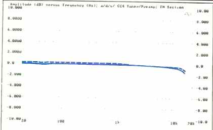
Fig. 1--Frequency response, FM tuner section.
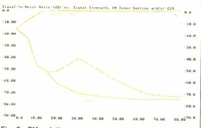
Fig. 2--FM quieting characteristics for mono (solid curve) and stereo (dashed
curve). TRD Heise (u) vs. Signal Level (ABE); FM Section, a/d/s/
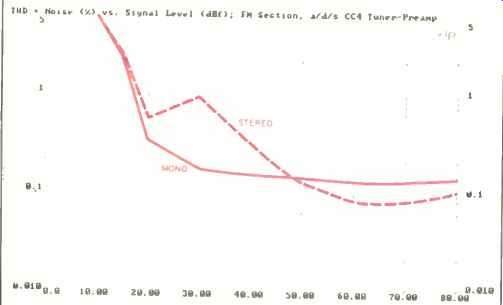
Fig. 3--THD + N vs. r.f. input level for mono signals (solid curve) and
stereo signals (dashed curve).
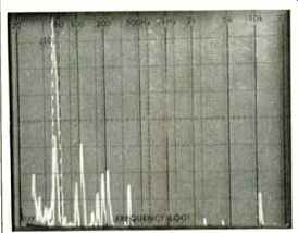
Fig. 4--THD + N vs. modulating frequency for mono (solid curve) and stereo
(dashed curve).
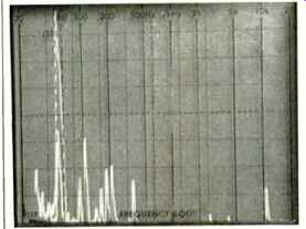
Fig. 5--Separation and crosstalk components for a 5-kHz modulating
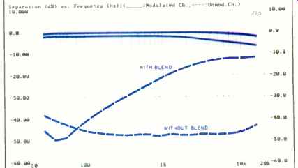
Fig. 6--Frequency response (solid curves) and separation (dashed curves),
with and without high blend. The lower of the two solid curves shows response
with high blend activated.
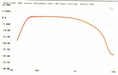
Fig. 7--AM frequency response for signal with NRSC pre-emphasis.
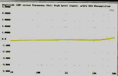
Fig. 8--Frequency response, preamplifier section.
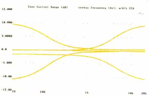
Fig. 9--Bass and treble control range. Note the drop in low-frequency level
with full treble cut.
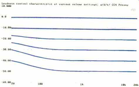
Fig. 10-Loudness compensation at volume-control settings from maximum volume
(top curve) to-50 dB (bottom curve), in 10-dB increments.
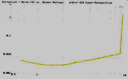
Fig. 11-THD + N vs. output voltage, using high-level inputs, for a 1-kHz
signal.
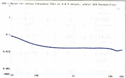
Fig. 12-THD + N vs. frequency, using high-level inputs, at 3 V rms output.
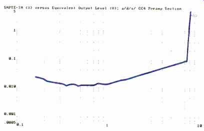
Fig. 13-SMPTE IM vs. output voltage, using high-level inputs.
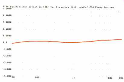
Fig. 14--Deviation from RIAA equalization.
Use and Listening Tests
As I have already mentioned, listening tests were conducted on the CC4 together with the PA4 amp, using primarily CD source material. In order to evaluate the phono section of the CC4, I had to dig out some of my old favorite LPs. Most remain in excellent condition, because it's been a long time since I have played any of them. The reference turntable in my lab remains the Thorens TD 126 MKIII, equipped as it has been 'or several years now with the Shure V15 Type V-MR cartridge. Reproduction of these vinyl discs was excellent, and it was nice to be able to adjust input sensitivities to match the levels of the tuner section, my CD player, and my DAT recorder. The front panel of the CC4 is truly a remarkable achievement; its layout is sensible and easy to follow, and the multitude of informative displays let you know just what you are doing.
The combined asking price for the PA4 and CC4 is a rather high $2,200, but in my opinion, if you become the owner of this system, you'll be the proud possessor of much more than just another tuner/preamp and power amplifier.
You'll be the owner of two perfectly matched components whose utility can be expanded and augmented by adding other superb, matching a/d/s/ Atelier components-not to mention that optional RC1 remote. Furthermore, if you then couple that remote with the RR1 remote receiver, system control will be able to move with you to any room in your home. It's this concept, added to excellent performance, which makes these Atelier components from a/d/s/ so appealing, despite the price.
--Leonard Feldman
a/d/s/ PA4 Power Amplifier
Manufacturer's Specifications:
Power Output: 150 watts per channel, 20 Hz to 20 kHz, into 4 or 8 ohms; 250 watts in bridged mode (mono), 20 Hz to 20 kHz, into 4 or 8 ohms.
THD: Less than 0.05%. Frequency Response: 20 Hz to 20 kHz, +0,-0.2 dB. IHF Dynamic Headroom: 1.5 dB into 4 or 8 ohms.
Input Sensitivity for 1 Watt Output: 100 mV.
S/N Referred to Rated Output into 8 Ohms: 110 dBA.
Damping Factor: Greater than 100.
Slew Rate: Greater than 30 V/µS.
Rise-Time: Less than 1.5 µS. Phase: Noninverting.
Power Requirements: 120 V a.c., 60 Hz, 800 watts maximum.
Dimensions: 17 1/2 in. W x 23 in. H x 14 1/4 in. D (44.5 cm x 7 cm x 37.3 cm).
Weight: 27 lbs. (12.3 kg).
Price: $1,200.
Company Address: One Progress Way, Wilmington, Mass. 01887, USA.
Like the CC4 tuner/preamp, the PA4 power amplifier is contained in a standard a/d/s/ Atelier module. This power amp is designed to deliver 150 watts per channel into either 8or 4-ohm loads. It can also be used in bridged mono mode, in which case it delivers 250 watts into a single speaker load.
The amplifier features switching for two pairs of speakers, or for two speakers when it is used in bridged mode. Its power and speaker switching can be controlled from a companion component, the a/d/s/ Model CC4 combination tuner/preamp.
The circuitry of the PA4 is extremely wideband, with extensive local current feedback in each stage. (Feedback in the main loop is kept moderate, to ensure stability.) Overall bandwidth is controlled by a passive roll-off of 6 dB per octave at the inputs. This all-discrete, bipolar-transistor amp uses 10 heavy-duty output devices in each channel to deliver high current output.
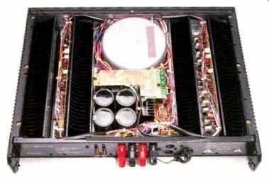
A massive toroidal transformer is used in the well-regulated power supply.
The PA4 uses no current- or voltage-limiting protection in its output stages.
Instead, the amplifier has a detector that opens the speaker relay in the event of gross current overload or large d.c. offset faults. The PA4 uses premium-quality components throughout, from its externally visible gold-plated input jacks to its extensive use of low-noise, metal-film resistors and polypropylene capacitors throughout its signal paths. Despite the PA4's relatively small size, the intelligent internal layout of its power-supply parts, heat-sinks, and circuit boards enable the amplifier to transfer away internally generated heat-even under the stressful conditions of my bench tests, many of which involved long-term delivery of rated or near-rated power output. I found that the top of the module became quite hot to the touch under these high power output conditions. At no time did the speaker relays open up during my tests, however, nor did the change in temperature alter the power output capabilities or low distortion readings I obtained for this beautifully designed amp.
Control Layout
A power button is at the left end of the front panel, and an indicator light above it glows amber when the power cord is connected to an a.c. source. When the power is actually turned on, the indicator color changes to green. At the extreme right are a pair of "Clip" indicators that flash when the distortion of the amplifier exceeds 0.5% for any reason.
Below these lights are a pair of speaker selector buttons.
The rear panel is equipped with color-coded pairs of speaker terminals, with appropriate terminals of each set marked for bridged connection. Gold plated phono-tip input jacks are nearby; the left one carries the additional rotation, "Bridge." A slide switch selects dual-channel or bridged mode, while another switch selects 4or 8-ohm load optimization. Two additional multi-pin DIN connectors on the rear can be used to receive power on/off and speaker-selector signals from the CC4 tuner/preamp and from future Atelier control centers. These connectors are in parallel, for loop-through signals to more than one PA4 amp. All Atelier components are supplied with a back cover which conceals the connections and channels all cables out one end, so the units look uncluttered even with their backs exposed.

Measurements
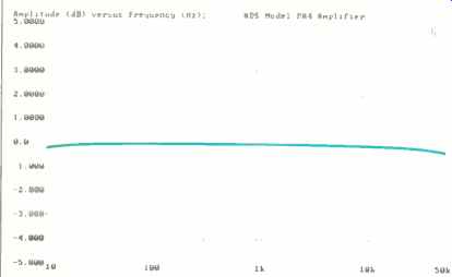
Fig. 1-Frequency response.
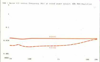
Fig. 2--THD + N vs. frequency.
Frequency response of the PA4 was within 0.1 dB from 13 Hz to 38 kHz, as can be seen in Fig. 1. Above 50 kHz, the upper limit of this graph, the roll-off was very gentle, reaching the-3 dB point at 300 kHz. Figure 2 shows how THD + N varied as a function of frequency for the constant rated output of 150 watts into 4 and 8 ohms, with both channels driven. In fact, for 8-ohm loads, THD + N hardly varied at all over the entire audio spectrum; it remained at about 0.017%, far lower than the 0.05% specified. The same test was repeated for 4-ohm loads, and since a/d/s/ specifies the same rated power at that lower impedance, I set the Audio Precision test generator to maintain the amp's output at a constant 150 watts per channel at all frequencies plotted. While this time there was a slight rise in THD as the higher test frequencies were approached, THD + N was still well below 0.02% at 20 kHz.
Figure 3A shows THD + N versus power output into 8-ohm loads for signals of 1 kHz, 20 Hz, and 20 kHz. The rated distortion of 0.05% was reached at an output of 158 watts, so a/d/s/ could have specified this as the rated power output for an 8-ohm load. At the published rating of 150 watts per channel, THD for the worst-case (20-kHz) signal was only 0.007%. Similar plots were made for 4-ohm loads (Fig. 3B). Although a/d/s/ conservatively rated the 4-ohm power output as 150 watts per channel, the curves reveal that the amplifier was able to deliver 220 watts per channel at mid-frequencies and 210 watts per channel at 20 kHz before the rated THD of 0.05% was reached. A 20-Hz input signal resulted in an output of 215 watts per channel for the same rated THD value. If I were to accept the published rating of 150 watts, even for a 4-ohm load, I would have to report the worst-case THD + N figure as only 0.014% (for a 20-kHz signal) as opposed to the rated maximum THD figure of 0.05%. In the bridged mode, I was able to drive the amp to nearly 295 watts using a 4-ohm load for the rated THD of 0.05%. Ail in all, the PA4 turned out to be one of the most conservatively rated amplifiers I have measured in a long time.
To complete the distortion analysis of this amp, I applied a standard SMPTE-IM signal to the inputs, varying the level to produce equivalent power output levels ranging from around 250 mV to clipping. Results for 8and 4-ohm loads are shown in Fig. 4. At rated output, SMPTE IM measured 0.006% with 8-ohm loads and 0.016% with 4-ohm loads.
Similar plots were made using two high-frequency signals, 18 and 19 kHz, as the input. The resulting "beat" frequency of 1 kHz, usually referred to as CCIF-IM distortion, measured 0.00022% at rated power for 8 ohms and 0.00032% for 4 ohms (Fig. 5). Input sensitivity for 1 watt output into 8-ohm loads was 97 mV. A-weighted S/N ratio, referred to 1 watt output, was 94.47 dB. Adding another 21.76 dB, to reference the S/N to the rated output of 150 watts per channel, yielded an A-weighted S/N rat o of 116.23 dB, considerably better than the 110 dB claimed by a/d/s/. Damping factor, using a 50-Hz signal into 8 ohms, was 96, while dynamic headroom measured 1.6 dB, slightly more than the 1.5 dB specified by the manufacturer.
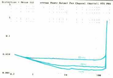
Fig. 3A--THD + N vs. power output for 8-ohm loads.
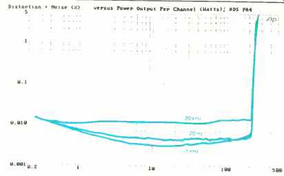
Fig. 3B--Same as Fig. 3A but for 4-ohm loads.
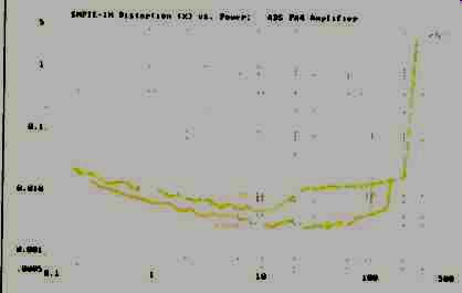
Fig. 4--SMPTE-IM distortion vs. power
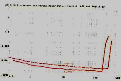
Fig. 5--CCIF-IM (twin-tone) distortion vs. power output.
Use and Listening Tests
It has been said that physical well-being (or lack of it), mental attitude, and other psychological factors influence one's judgment when listening to, and trying to evaluate, the sonic qualities of audio equipment. If this is true, then I must confess that I was predisposed to think very well of the a/d/s/ PA4. I am favorably impressed by superb engineering, good product styling, and intelligent ergonomics. The PA4 boasts all of these attributes. That having been said, you can guess that I thought the sound quality of this compact and neat-looking amplifier was superb. My listening tests involved using the PA4 together with the a/d/s/ CC4 tuner/preamplifier, which arrived at my lab along with the amp. To eliminate the possibility of too many variables, I also played CDs by connecting the variable outputs of my reference CD player to the inputs of the PA4. Not only could I detect no difference in sound balance or quality between these two setups (which speaks well of the "straight wire" qualities of the CC4 tuner/preamp), but the overall sound quality in both cases was particularly open and devoid of any veiled quality.
Two of the several CDs I used especially illustrate this sense of open, unveiled, and smooth sound: A new Telarc release called Big Band Hit Parade (CD-80177), featuring digitally recorded arrangements of some of the greatest hits of the '30s and '40s, and a Bainbridge Records remastering of a 1964 recording of Virgil Fox playing the giant John Wanamaker Organ in Philadelphia (BCD-2501). The Bainbridge disc was archived with the Colossus system of digital recording developed by my old friend Lou Dorren, who is now with a company called By The Numbers.
The accurate reproduction afforded by these a/d/s/ components makes it easy to pick out other good software from my growing collection. With electronics this good, it's a lot easier, and more fun, to differentiate between excellent and not-so-great program material. And that's one of the hallmarks of first-rate electronics-that it enables you to easily distinguish between good and not-so-good software.
-Leonard Feldman
(Source: Audio magazine, Mar. 1989)
Also see:
ADS C2 Cassette Deck (July 1983)
ADS CD4 Compact Disc Player (June 1987)
Ace Audio Model 4100 Filters (Mar. 1982)
= = = =