MANUFACTURER'S SPECIFICATIONS:
Tuner Section: IHF Sensitivity: 2.4 V. Selectivity: 80 dB. S/N: 65 dB at 50 µV input. THD: (Mono) 0.3%; (Stereo) 0.5%. Stereo Separation: 40 dB @ 1000 Hz. Sub carrier suppression: 60 dB.
Amplifier Section: Power Output: 120 watts total IHF music power, 8-ohm load.
RMS Power Output/channel: 40 watts, 8 ohm load. THD: 0.3% at rated output. IM: 0.3% at rated output. Power Bandwidth (IHF): 20 to 20,000 Hz. Hum and Noise: High-Level Inputs:-80 dB. Phono: 1 µV equivalent input. Damping Factor: Greater than 35 for 8-ohm load. Input Sensitivity: Phono: 2 mV; High Level: 180 mV. Phono Frequency Response: RIAA ± 0.5 dB.
General: Power Requirements: 105/125 V a.c., 50/60 Hz, 33 watts at idling to 220 watts both channels driven to full output.
Overall Dimensions: 17" w. x 5-9/16" h. x 15" d.
Suggested Retail Price: $425.00 in metal wood-grained enclosure. (Walnut enclosure optional, extra.)
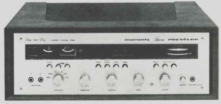
Fig. 1
The Marantz Model Twenty Two is the first all-solid-state receiver offered by that distinguished company! Before readers take pen in hand to cite the Model 20 reviewed in December we hasten to add that this unit was equipped with a vacuum tube-the famous oscilloscope tube which served as a tuning aid and audio monitor. This feature is not included in the 22-with a consequent saving in cost-offset to some extent by the inclusion of an AM band. The IF system uses 3 IC's with ceramic interstage filters to provide a controlled bandpass and the FM front end utilizes two FET's plus a conventional transistorized local oscillator.
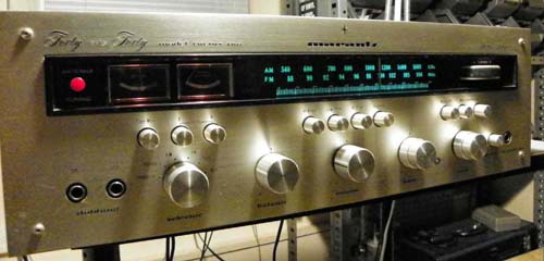
The Twenty Two has the traditional Marantz front panel look, including the horizontally mounted, direct tuning thumb flywheel introduced on earlier Marantz tuners and receivers, as can be seen in Fig. 1. The upper half of the gold and black panel is devoted to the tuning wheel, dial scale, stereo indicator light, two tuning meters and a pushbutton called "Antenna Tuning." This button, used in conjunction with one of the two tuning meters, provides one of the important functions previously assigned to the `scope tube on earlier models-the facility of rotating an FM antenna for least "multi path" reflections using a visual indicator. More about its use later. Ordinarily, the meters act as center-of-channel and signal-strength indicators for FM tuning, while the second meter is only active in AM tuning, as a signal-strength indicator.
The lower portion of the panel is tastefully fitted with knobs and pushbuttons, all of turned metal and all arranged so intelligently as to provide total familiarity after about five minutes of exploration.
Major rotary knobs include a six-position selector switch, balance control, volume control, and dual-concentric clutch-type bass and treble controls. The cluster of three push-push buttons at the left include the tape-monitor function and L and R mono-mode buttons. The latter provide a unique way of getting either L or R alone from both speakers. If both buttons are depressed, the usual mono mix of L & R is obtained. The central cluster of four similar buttons offer "Hi Blend," a cross-mixing of high frequencies for reducing noise (while at the same time reducing high-frequency separation)
in marginal stereo FM receiving situations. This button is followed by low- and high-frequency cutoff filters and a loudness (or contour) button. The final, leftmost group of three more buttons provides for mute-defeat and selection of main, remote, or both sets of speakers.
With neither speaker button depressed, sound will be heard only through headphones when they are connected to the front-panel headphone jack. A pair of "dubbing jacks" ( duplicating the rear panel "tape in and tape out" jacks) and a push-push power on/off button complete the front-panel makeup.
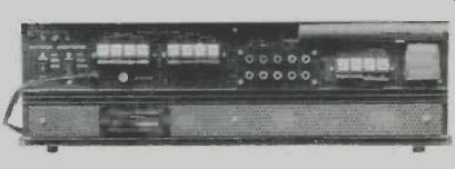
Fig. 2-Rear panel view.
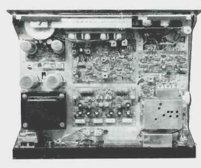
Fig.
3-Showing internal construction.
The rear-panel layout, shown in the photo of Fig. 2, includes one switched and one unswitched convenience outlet, a thermal relay reset button, the usual input and tape-output jacks, an FM input attenuator switch ( which reduces input signal strength by 20 dB in cases of severe overload-which we never encountered), a muting threshold adjustment and a good sized grounding terminal for use with external record changer, turntable or tape deck. The muting adjustment is a most worthwhile feature, for users in different locations will want to set the mute adjustment to suit individual conditions. The range of this adjustment, we found, enables the mute to be overcome at signal levels from 5 µV to about 25 µV. Speaker and antenna connection terminals are by far the simplest and most reliable type ever invented-and they have been appearing with increasing frequency on the latest crop of receivers, particularly those imported from abroad. Piano-key tabs are depressed, exposing a small hole, into which the stripped end of a speaker or antenna wire is pushed. Releasing the key-tab, which is spring loaded, clamps the wire firmly in place. There are no screws to loosen, no wires to twist under the heads of screws and, best of all, the possibility of shorts is all but eliminated. This scheme is used on both antenna and speaker terminals in the Model Twenty Two. Antenna terminals permit either a 300-ohm or a 75-ohm cable to be properly matched, though the customer instruction manual favors the use of shielded 300-ohm lead-in cable, to minimize multi path interference.
Eleven individual circuit modules, including completely separate FM and AM front ends, are used in the rugged chassis.
At least some of the layout can be seen in Fig. 3 and, while the AM-IF, FM-IF and FM-Stereo circuits are all assembled on one p.c. board, they are totally separate circuits too. The stereo decoder circuitry has been simplified by the use of a new integrated circuit which, together with three external tuned circuits, is all that is required to decode the composite stereo signal into separate left and right outputs. Five other integrated circuits appear in the FM-IF and audio circuits.
In addition, there are fifty three bi-polar transistors, four field-effect transistors and some thirty-eight signal, regulating, and rectifying diodes in this receiver design.
Electrical Measurements
It should come as no surprise to anyone acquainted with previous Marantz products to learn that in many instances, performance measurements exceeded published specifications. For example, the actual measured IHF sensitivity was 2.1 µV as opposed to the 2.4 µV claimed.
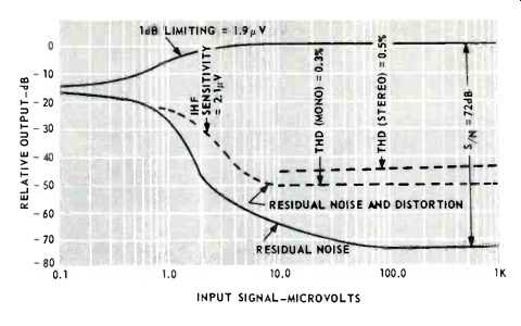
Fig. 4--FM characteristics of Marantz 22.
Furthermore, this figure was equaled at all three test frequencies (some manufacturers try to squeak out their best figures at 98 MHz, sacrificing the end points, since IHF sensitivity is supposed to be measured at that one frequency). Ultimate S/N for mono FM reached an incredible 72 dB at 100 µV and even with an input signal of 50 µV, for which Marantz claimed a S/N of 65 dB, we read 71 dB. Full limiting was reached at just under 2µV, a fact which Marantz does not mention, but one which, in our opinion, separates the really good FM performers (such as this one) from the run-of-the-mill tuners. Figure 4 graphically illustrates these important FM characteristics, while Fig. 5 is a plot of stereo FM separation. While we were able to obtain only 38 dB of separation at 1 kHz, that is close enough to the 40 dB claimed, and both figures are more than adequate. In fact, we did measure 40 dB at 400 Hz and maintained at least 30 dB of separation down to 50 Hz and up to about 8 kHz. At 15 kHz separation was down to 23 dB. Figure 6 is a plot of both THD and IM, referencing an 8-ohm load with both channels driven. Rated distortion of 0.3% is reached at 43 watts in the case of THD and at 41 watts in the case of IM, both results above published claims. There is no evidence of increasing distortion at lower power levels, sometimes typical of complementary-symmetry output-circuit configurations and, more significantly, wattages just below maximum output are produced with barely measureable IM and THD (both well below 0.1%). In the case of THD, our equipment is capable of measuring down to 0.05%, and this is what we measured, indicating that actual distortion at lower power output levels was probably better than that very low figure.

Fig. 5-Stereo separation.
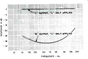
Fig. 6-THD and IM characteristics.

Fig. 7--Tone control and filter characteristics. Fig.
8--Power bandwidth.
Tone-control action, loudness-contour compensation (at 30 dB below full volume), and low-frequency and high-frequency filter action are all plotted in Fig. 7. The filters have a slope of only 8 dB per octave and therefore cut into the program material to a greater extent than we would like to see. For example, the "rumble" filter causes the low-frequency response to be down about 5 dB at 80 Hz and the scratch filter attenuates 7 kHz signals by a similar amount. Chances are, however, that owners of this equipment will seldom want to use these secondary circuits anyway, if companion equipment and source material is in good condition. Power Bandwidth, plotted in Fig. 8, extends from 15 Hz to 30 kHz, considerably beyond published claims.

Fig. 9--Square-wave response at 100 Hz (A) and 10,000 Hz (B).
Listening Tests
Since our laboratories are equipped with an antenna rotor, we were able to put the "multipath meter circuit" to the test, and a word about its novel approach is in order. When the antenna tuning button is depressed, two changes occur in the FM tuner circuitry. The output of the IF system is fed to an AM detector, rather than to its normal FM ratio detector. It is characteristic of multipath reflections to cause partial out-of-phase cancellation of the incoming signal. This results in an IF signal which is not fully "limited" and therefore has AM modulation riding upon it. The output of the AM detector is fed to the audio chain, so that with the Antenna Tuning button in its depressed position, we can hear the products of AM detection audibly. Their presence indicates multipath! These same AM products are rectified to create a pulsating d.c. voltage, which is applied to the meter used in this mode. As the antenna is rotated, the audible AM products reach a null, and so does the meter reading. The "null" is therefore the optimized position for the antenna and the test is quick and accurate. 'In this application, we feel that this method of antenna orientation is as easy to use as the `scope method previously featured on Marantz products and it is certainly less costly and requires no high-voltage power supply. As for the effectiveness of FM reception, we were able to pick up 43 stations using just an indoor dipole, reorienting it as demanded by the "antenna meter." Shifting to a multi-element outdoor directional antenna increased the number of usable FM signals received to 57, of which some twenty-two were broadcasting acceptable stereo. For our location ( about twenty miles from the New York Metropolitan Area center) this is an extremely good record.
Marantz makes no claims whatever for its AM performance, even excluding all reference to this section in its published specifications. We wonder why, since we found the AM reception to be more than adequate and quite sensitive. Bandwidth seemed a bit on the narrow side compared to quality sets we have tested, but this in turn meant no serious "10-kHz" whistle problems, even during evening listening.
All the while, the amplifier section of this receiver coasted along at all our test listening levels, never breaking up and never tripping the thermal protection circuits, even under extreme dynamic listening conditions, using two pairs of stereo loudspeaker systems, each rated at 8-ohms impedance and both sets of the low efficiency variety, at that. Square-wave response at 100 Hz and 10 kHz is shown in the 'scope photos of Fig. 10, confirming the better-than-average transient response which we noted in our listening tests.
In all, it is obvious that Marantz engineering has combined with overseas fabricating facilities to produce a receiver worthy of the Marantz name and tradition, yet within the reach of many more pocketbooks than would otherwise be the case.
(Audio magazine, Apr. 1970)
Also see:
Marantz Model 2500 Stereo FM/AM Receiver (Feb. 1978)
Marantz Model 1150D Stereo Control Amplifier (Mar. 1976)
Marantz PM-94 Integrated Amplifier (Dec. 1988)
= = = =