by George W. Tillett
[Some of this material was previously published In the British Audio Annual (HI-FI News) 1965, to which due acknowledgements are made. ]
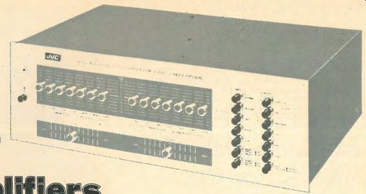
--- JVC Model 5011
MANY YEARS ago, in 1880 or thereabouts, Lord Kelvin said, "I often say that when you can measure what you are speaking about and express it in numbers, you know something about it. When you cannot express it in numbers, your knowledge is of a meager and unsatisfactory kind." Very true-but if you cannot understand the numbers or their significance, then your knowledge is still unsatisfactory.
Technical specifications of any kind can be very confusing to the beginner, and those relating to amplifiers are certainly no exception. Indeed, the multiplicity of standards and the trend of some manufacturers to use artificial power output figures, for instance, make translation quite difficult for engineers--let alone beginners.
Before we take a look at the figures and see what they mean and what really matters, it will be as well to list the basic requirements of a stereo amplifier--and here we will include separate preamplifiers and power amplifiers, combined or integrated units as well as the amplifier sections of receivers.
Here they are, not necessarily in order of importance: Low distortion, wide frequency range, high damping factor, adequate power output, unconditional stability, low hum and noise levels, low crosstalk, good channel matching, and adequate tone controls, filters, and general facilities. Add to these, reliability and ease of handling plus good styling.
Distortion
The perfect amplifier does not yet exist, in spite of the claims to the contrary, and even the best, the most expensive, do not reproduce an exact replica of the input signal--99.99% perfect--well-perhaps! Both tubes and transistors are inherently non linear devices but special circuits and the use of negative feed back can reduce the distortion to insignificant amounts. Distortion can be divided into two kinds-harmonic and inter modulation, although as far as amplifiers are concerned, both are somewhat interrelated. Harmonic distortion means the generation of spurious harmonics of the input signal. Thus if a pure 50 Hz note is applied to a poor amplifier, it would come out as an amplified 50 Hz fundamental plus a certain amount of 100 Hz second harmonic, 150 Hz third, 200 Hz fourth, and so on. Figure 1(a) shows a distorted waveform with a high second harmonic content. As a matter of interest, an amplifier that had only second harmonic distortion might not sound too bad. As is . well known, all musical instruments depend on the production of harmonics (or partials) for their characteristic tone color or timbre. This is why a note played on a flute, for instance, sounds different from the same note played on a clarinet or trumpet.
Moreover, the relationships of harmonics and fundamentals determine the tone quality of such instruments as the Violin or piano, so if our amplifier only changed those relationships, the results would not necessarily be that unpleasant. Indeed, it might merely convert a grand piano into an upright or vice versa (see Fig. 2). One thing is certain however, the high-order harmonics--the 5th, 7th, 9th, etc. which are not harmoniously related to the fundamental in the musical sense-are objection able even if present in small proportions. Figure 3 shows how harmonic distortion is measured with a wave analyzer. This instrument is tuned successively to the harmonics of the test frequency-usually 400 or 1000 Hz and the readings are expressed as follows:
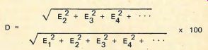
...where D = percentage of total harmonic distortion, E1= amplitude of fundamental voltage, and E2 = amplitude of second harmonic voltage, etc.
Because high order harmonics are progressively more un pleasant, many authorities advocate a "weighted" distortion factor in which the harmonics are weighted in proportion to their relative unpleasantness [1]. Obviously it is very difficult to assess relative unpleasantness and so the weighted system is not often used. A simpler method of measuring harmonic distortion is by using a bridge type of instrument that balances out the fundamental, leaving all the spurious harmonics to be measured as a total percentage. Figures obtained by this method are listed in specifications as Total Harmonic Distortion (THD) . at a specific input frequency, usually 1000 Hz.
Intermodulation Distortion
This is the production of spurious sum-and-difference frequencies when two or more frequencies are passed through a non-linear amplifier. Figure 1(b) shows a 50 Hz and a 1000-Hz · note applied to an amplifier which we will label B. It is a reasonably good amplifier and so the resultant waveform is fairly pure. However, if we apply the same frequencies to amplifier A, it is quite a different story. The distorted 50 Hz note deforms the 1000 Hz waveform by inter-modulating it as shown in Fig. l(c). In this process it creates a whole series of sum-and difference frequencies--1050, 950, 1,100, and so on. · These spurious frequencies play havoc with the reproduction of music as they are not harmonically related to the original tones. Most of the harsh distortion associated with overloading and Class :a crossover distortion is due to intermodulation or IM. There is no simple relationship between IM and HD but with well de signed tube amplifiers it is normally 4 : 1. In other words, 0.25% HD roughly corresponds to 1% 1M-up to overload point. There is no correlation for. transistor amplifiers where the IM is largely dependent on crossover distortion. Many of the early transistor amplifiers had a significant amount of IM distortion that actually increased at low output levels (see Fig. 4). Crossover distortion tends to produce more IM than harmonic distortion moreover the higher order. harmonics predominate. This brings us to the big questions: How much distortion can we actually hear, and how much is acceptable? Various tests have been made in the past and the general conclusion is that a THD of 0.5% at 1000Hz can just be detected. Under domestic conditions · it is possible that most people could tolerate a rather higher amount-especially if one considers the limitations of most program sources. But, bearing in mind the subjective unpleasantness of the high-order harmonics and the fact that we do not usually know their percentages in the quoted figures, it is best to play safe. A good amplifier, then, should not have a greater distortion than the following: 0.3% at 1000 kHz, 0.6% at 40 Hz and I% at 10,000 Hz. Most specifications only give the 1000 Hz figures . but if the distortion rises appreciably at the ends of the spectrum, it will normally show up in the IM figures. Standard IM frequencies are 40 and 7000 or 70 and 7000 Hz in a ratio of 4: 1 and IM distortion should not exceed 1.5% at any level up to rated power output.
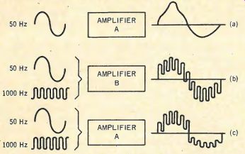
Fig. 1--Harmonic and intermodulation distortion.
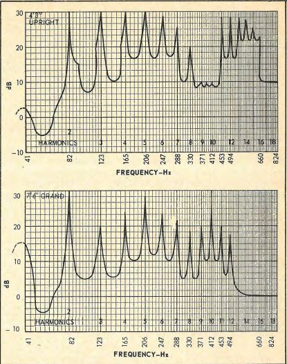
Fig. 2--Harmonics of E3 (41.2 Hz) produced by two pianos using equal hammer
velocity. (From "Pianos, Pianists, and Sanies" by G. A. Briggs,
Cahners Publishing, 221 Columbus Ave., Boston, Mass. 02116.)
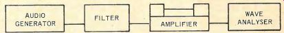
Fig. 3--Wave-analyzer method of testing amplifier distortion.
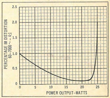
Fig. 4--Showing intermodulation distortion characteristic of a typical early
transistor amplifier.
Frequency Response
What should the frequency response be? I would say 5-Hz to 70-kHz within 1 dB for a really good amplifier, but the band width could be reduced to 20 Hz - 30 kHz within 3 dB without losing too much "fi ." Seventy kHz might seem a little high for the roll-off point but many authorities believe that the overall bandwidth ought to extend up to 200-kHz or higher. Others say, "Wideband amplifiers are strictly for the bats." What is the truth about the matter? Well, there are several reasons for the high upper limit. Here are some of them:
1. The internal bandwidth of an amplifier using a large amount of negative feedback must extend to at least one octave above the audio range to maintain stability,
2. Assuming a flat response up to 20 kHz is required, then the rate of attenuation above this frequency must not exceed 6 dB per octave to avoid "ringing," and
3. To reproduce square waves properly the pass-band must be ten times the input frequency. The difficulty here is to equate square waves with music and some experts maintain that it is only necessary for an amplifier to pass square waves up to 4 kHz, thus indicating a response up to 40kHz. There is a school of thought which goes much further than this [2].
Their argument is based on the Helmholtz theory that most music really consists of a series of tiny transients that blend together in our ears, and they claim that an amplifier must therefore be able to reproduce a square wave of 20 kHz without distortion. This means a bandwidth of ten times 20 kHz or 200 kHz. One reason why this point of view is not widely accepted is the limitations in program sources but one thing is certain-the higher frequencies play a more important part in fidelity of reproduction than was thought possible some years ago. Tests have been made indicating that the removal of frequencies above 20 kHz or so can be detected by listeners who are deaf to anything above 15 kHz. One such experiment described by Slot of Philips involved two scientists, one of whom was absolutely, deaf to frequencies above 10kHz and the other above 11kHz [3]. Both could unfailingly tell when a filter was switched into circuit that brought the highest limit down from 18 kHz to 12kHz. Slot goes on to say, "It may be that the highest frequencies, even though they are not actually observed, still give rise to inter modulation within the hearing system and that the absence of these subjective intermodulation tones is considered unnatural." Experiments carried out some years ago at Wharfedale with very wideband amplifiers were not conclusive: sometimes listeners preferred a response up to 200 kHz, sometimes a more restricted range was considered more natural-depending on the program material. It would seem logical to assume that if the upper frequencies do contain some kind of information, then they could also add to the sum total of distortion. In other words the wider you open the window, the more dirt blows in.
So it would seem essential that a very wide band amplifier should have a switched filter to give best results. Summing up, an overall frequency range (measured at 1 watt) of 5 Hz to 70 kHz within 1 or 2 dB really represents a middle-of-the-road approach, with 20 Hz to 30 kHz within 2 dB being the lower limits. Incidentally, frequency range should always be quoted with a dB reference, the often used formula "frequency response 2 to 50 kHz" or whatever being virtually meaningless.
Power Output
How much power is needed? What with experts recommending anything from 5 to 500 watts and speaking about sine-wave power, Music Power, peak power, and so on, it is no wonder many people are a little confused. Ample power should be available to handle peak transient signals without distortion and how much is enough depends on the size of the room, speaker efficiency, and personal taste (and possibly that of the neighbors). Speaker efficiencies range from the 25% of the large horn systems right down to the meager 0.5% of the small book shelf models. So 1 watt fed to a large horn system would make as much noise as 50 watts into a bookshelf unit. A good average figure is 3% increasing to 5% for larger floor models. A total power of 30 to 70 watts would be needed for a small to average size room, increasing to 100 watts total for a large room. These figures refer to old fashioned rms watts, not Music Power. What exactly is Music Power? According to the IHF it is "the greatest single frequency power that can be obtained without exceeding the rated total harmonic distortion when the amplifier is operated under standard test conditions, except that the measurement shall be taken immediately after the sudden application of a signal and during a time interval so short that supply voltages within the amplifier have not changed from their no signal values." In practice, this means using an external stabilized power supply.
Obviously, if the d.c. voltage remains constant, then the Music Power will be the same as the rms, sine wave, or continuous power. On the other hand, if the power supply is badly regulated, then the Music Power rating will be a lot higher than the rms figure. Put another way-the power supply IS so designed that it will only deliver full voltage for a very short duration, so if the signal is not a sine wave but merely consisted of transient peaks lasting a few milliseconds, the supply voltage would remain constant.
This is a very comfortable theory because it enables considerable economies to be made-not only with the power supply transformer, rectifiers, and capacitors, but with the output transistors and their large expensive heat-sinks. More than this, it enables an unscrupulous manufacturer to double or even triple the apparent output figures. But of course, there are snags-for one thing there is no agreement as to how long the music transient peaks shall be. Peak powers of some organ works like Bach's Toccata and Fugue in D are quite long in duration and the demands of some kinds of electronic music are even more stringent. The only safe guide is to judge an amplifier's power performance by the rms figures and to bear in mind that the Music Power rating should not exceed the rms figure by more than 30%. The specified power should apply when both channels are driven. Note also that power output is usually greater for 4 ohm than for 8 ohm loads.
That ± 1 dB Rating
Sometimes used in specifications as "Power output, 100 watts ± 1 dB," "± 1 dB" is a dishonest method ¢f rating, as we have often pointed out. It is roughly equivalent to 21%, so that the 100 watt amplifier only need put out 79 watts!
Overload
An amplifier should have a smooth overload characteristic with almost instantaneous recovery. A poorly designed power supply not only fluctuates in d.c. voltage according to the signal, but produces severe distortion near overload point due to a superimposed sawtooth "hum" waveform caused by insufficient smoothing at high currents.
Power Bandwidth
This can be defined as the frequency range that lies between the extremes where the available power falls by half or 3 dB. Figure 5 shows the power response of two amplifiers, one giving half power at 15 Hz and 45 kHz and the other (Amplifier A again) at 55 Hz and 8.5 kHz. Note that both give their rated power at midband and so both could be sold as 50 watt amplifiers. These days when output transformers . are as rare as_ acoustic phonographs, loss of power at low frequencies is not too common but reduced output at the very high frequencies caused by transistor limitations is occasionally found. How important is power output at high frequencies? It used to be thought that full power was not necessary above 8 kHz or thereabouts. But with improvements in program sources and sound equipment as a whole, it has been found that the upper limits ought to be a good deal higher. For instance, the upper partial or harmonic of the cymbals at 18 kHz has an amplitude equal to the 680 Hz fundamental and this instrument can still put out considerable power at 25kHz. [4]. To be on the safe side, the half-power point should not be much lower than 30 kHz.
(Some of the best transistor amplifiers can deliver half power to well over 50 kHz and full power up to 20 Khz.) At the lower end, full power should be maintained down to at least 30 Hz although some authorities say that 40 Hz is a more reasonable figure. It is true that the lowest fundamentals of some musical instruments such as the piano, contrabassoon, and harp (believe-it-or not) are below 40 Hz but as a general rule the second and third harmonics are greater than the fundamental. However, there are no great problems in designing solid-state amplifiers to give full power at the low end, and so in practice a good amplifier will have a power bandwidth of 15 to 30,000 Hz at 3 dB.
Damping Factor
This is the ratio· of load impedance to the amplifier's internal impedance. A ·damping factor of 50 which is a typical figure for modern amplifiers, means that at the nominal output impedance of 8 ohms, the output resistance would be 8 divided by 50 or 0.16 ohms. A high damping factor means that the loudspeaker "sees" a low resistance which tends to damp any tendency for the diaphragm to vibrate at its natural frequency or resonance.
It might be thought that the higher the damping factor, the more efficient this acoustic brake becomes, but in practice any increase above 20 results in little ·further improvement.
This is because the resistance of the speaker voice coil is effectively in series with the output. Long speaker leads will also have an effect, as will crossover coils.
Transient Response
Transients are usually defined as sounds of short duration such as made by cymbals, piano, and other percussion instruments. However, they are also produced by many other instruments at the start of notes. Indeed these sounds play a significant part in stereo location [5]. It is fairly well known that amplifiers must have a wide frequency response to reproduce transients properly, but there are other factors involved. The response must be free from peaks and supersonic oscillations which can cause severe transient mutilation or "ringing." Most amplifiers these days use a high amount of negative feedback, · and it is essential that the high frequency response is carefully controlled with the necessary phase correction.
Square-wave signals are used for testing and Fig. 6 shows four response characteristics: A shows a slight overshoot or ringing due to a small peak at about 60 kHz and B shows the effect of a larger peak; this type of spurious oscillation may be continuous or it might be triggered off by an input signal or "switching transient." Curve C has a restricted high frequency response which shows up as a rounding of the square wave, and D has a wide frequency response giving excellent square wave resolution with very slight rounding. Amplifier B would certainly sound "edgy" and harsh, while C would sound dull and lacking in "attack." Amplifier A--the one with the small peak would be more unpredictable in how the ringing might be modified by the speaker load; it may improve slightly or it might even be triggered into an incipient oscillation like amplifier B. Transient response can also be adversely affected by some types of tone control, steep-cut filters. As far as specifications are concerned, few makers specify square wave rise time which indicates both transient response and bandwidth to some extent, but 3 microseconds at 10,000 Hz would be considered excellent (See Fig. 7). In any case, a 1000 Hz square wave should be reproduced without rounding or overshoot (with tone controls in the "flat" or cancel position). Above 7,000 Hz the waveform will show appreciable rounding-depending on the overall frequency response. · Sometimes inductive-capacitive loads are used for testing (no loudspeaker behaves as a pure resistance), arid slight overshoot at higher frequencies is permissible under these conditions.
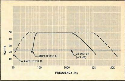
Fig. 5--Power bandwidth of two amplifiers.
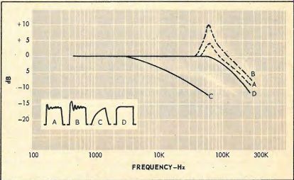
Fig. 6--Responses with 10kHz square wave resolutions.
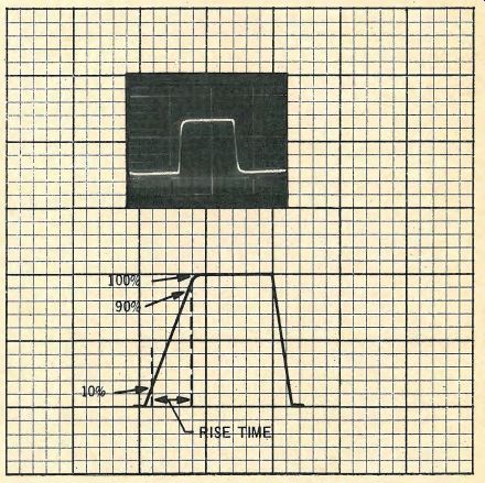
Fig. 7--The square wave rise time is the time taken to achieve 90 percent
resolution from 10 percent.
Stability
Not often mentioned in the specifications but important for all of that is stability. A really good amplifier should be unconditionally stable, which means that there should be no signs of instability with any combination of inductive and capacitive loads. Because of the high amounts of negative feedback used to reduce distortion, the stability margin on some amplifiers might not be very great. Consequently, severe load conditions such as those caused by complex crossovers might result in sufficient phase shift to cause positive feedback or instability.
In practice, the only complex load likely to be encountered would be electrostatic speakers, and readers who are contemplating the purchase of such speakers should check that their amplifier is suitable.

-----------
Tone Controls
Dealing now with the preamplifier section we come to the tone controls. All control units have bass and treble controls some have bass, middle, and treble and some divide the spectrum into even more ranges. The intention is to provide means of compensating for studio acoustics, recording deficiencies, room acoustics, and so on. For normal use a lift and cut of 10-12 dB at 40Hz and 10,000 Hz is more than adequate.
Two types of control are in common use, the passive type and a feedback type originated by P. J. Baxandall. The passive type has the effect (see Fig. 8) of rotating the response about a central hinge, usually 1000 Hz but the Baxandall type works in a different manner as the boost and cut are initially confined to the ends of the scale (see Fig. 9). This has the advantage that the lower bass frequencies can be boosted without appreciably affecting the 300 to 500 Hz region. At the treble end, the Baxandall would function like a filter in the cut position, but on the other hand you could not get a lift from- the mid-range if so desired unless you turned the control almost fully up.
So, both methods have their advantages and disadvantages.
The addition of a mid-range control makes for greater flexibility--so do the more complex 4 and 5 unit controls.
Whether such refinements are worthwhile is a matter of economics and personal choice. In most amplifiers the tone controls are ganged so both channels are controlled together but independent controls are provided on a few more elaborate amplifiers.
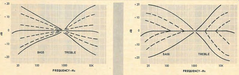
Fig. 8--Typical passive tone control characteristics.
Fig. 9--Baxandall tone control characteristics.
High Frequency Filter
In order to reduce distortion produced by imperfect broad cast transmissions, tape hiss and those "barbed wire strings" favored by some recording companies, it is sometimes necessary to restrict the high-frequency response by means of a filter.
Most of this distortion, especially pickup tracing distortion, affects the higher frequencies or upper harmonics, and the usual tone controls cannot always deal with it without destroying too much of musical value (throwing out the baby with the bath-water). In its simplest form then, a filter might consist of a single switched unit operating from about 7 kHz although sometimes a choice of two frequencies such as 4kHz and 8 kHz might be given. Many European amplifiers are fitted with more elaborate filters giving a continuous attenuation from 4 to 20 kHz-plus another control which can vary the actual rate of slope.
Low Frequency Filter
Sometimes termed a RUMBLE FILTER as this is its main function. It has been said that the rumble filter is a sign of defeat.
Perfectly true, but it may well be the best practical way of dealing with the problem. Even quite expensive transcription motors produce some rumble, which is accentuated by stereo pickups that are, of course, sensitive in the vertical direction. A speaker system that is very efficient at the low end could show up rumble but it must be emphasized that rumble at subsonic frequencies can produce considerable IM distortion by over loading the output stage or speaker system although it cannot be heard as a specific sound. Some pickup arms have what is in effect a built-in rumble filter. (Some have resonances that could make matters worse!) But in any case, a low frequency filter is desirable . lf it is switched, a frequency of 40 Hz would be a good choice but if the filter is built in, then 20Hz would be a better compromise. Most filters merely consist of a switched capacitor so in order to arrive at a reasonable attenuation, the roll-off point has to be about 200 Hz-so we have another case of throwing that baby out with the bathwater!
Loudness Control
This originally was a separate level control that automatically lifted bass (and to a smaller extent treble) at lower volume settings. These days it refers to a switch that changes the circuitry to permit the normal volume control to perform those functions if so desired. At one time, much controversy centered about the need for such controls. Advocates refer to the Fletcher Munson intensity curves which prove that the human ear is non-linear and that more power is needed at the low frequencies to produce the same apparent loudness when listening at low volume levels. Most readers are probably familiar with the Fletcher-Munson curves, which are shown in Fig. 10. Note that the curves are relative and that they are almost parallel above 2000Hz. Now the theory is this: Suppose a symphony orchestra produces an intensity of 90 phons, and (out of consideration for the neighbors) we wish to reproduce this at a level of 70 phons, we apply compensation based on the difference between the appropriate level curves as shown in Fig. 10 and everything is fine . But is it?
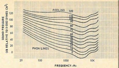
Fig. 10--Fletcher-Munson equal loudness curves.
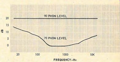
Fig. 11--Relative level curves.
Critics say that the Fletcher-Munson curves were taken with sine waves and because of the effects of intensity on pitch arid harmonic structures, they cannot apply to music. Moreover, we listen to live music at various intensities without being worried by bass deficiencies . They go on to ask, "Does an orchestra really sound that unnatural when we listen some distance away?" It is possible that the desire for bass lift when listening at low levels is a psychological one but the situation is complicated by the fact that some speaker systems, particularly reflex types and very small bookshelf models, are non-linear and sound a little thin at low volume levels.
So is a loudness control necessary or not? My own opinion and I stress that is a personal opinion- is this: If you have a really good speaker system it is doubtful if you will feel the need for such a facility. On the other hand, it does not cost much to provide and you need not use it if you do not want to! Another personal opinion:. It really ought to be called a "softness" control!
Hum and Noise
A combined figure is usually quoted for hum and noise. The hum component consists of a mixture of power line frequency (60Hz here) plus some second and other harmonics due to smoothing deficiencies, power transformer radiation, etc. The noise or hiss is due to random impulses generated by tubes, transistors, resistors--in fact any component passing current. It is almost aperiodic in form, that is, it is not con fined to any particular frequency or bands of frequencies. In practice, there is an identifiable low-frequency component caused by transistor current variations.
Specifications usually quote the figures for hum and noise in decibels related to the full rated amplifier power output. The disadvantage of this method is that a large amplifier can have identical noise figures to a smaller one but the background would be higher. Thus a 10 watt amplifier might have a measured noise of 10 millivolts at the output. This is one thousandth of 10 watts or 60 dB. But a 100 watt amplifier with the same 10 millivolts of noise would have a noise level of -80 dB referred to full output! Some makers use a 1 watt reference figure, but if the full power figure is used then this must be borne in mind when making comparisons.
The important question is: How much hum and noise can we accept and how much is inaudible? Here it is difficult to give a precise answer, as a lot depends on the proportions of hum and noise, the frequency response of the amplifier, response and sensitivity of the loudspeaker system, room acoustics, ambient noise, and other factors. Noise can be accentuated by peaks anywhere in the system, particularly in the speakers, and a spectacular improvement can often be obtained by replacing the treble unit with a better one having a smoother response. This will, of course, not only reduce background noise but it will have an effect on tape hiss and record noise too. As a general guide, hum and noise should not exceed the following:
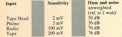
Table
Preamplifiers are usually rated with respect to the output voltage which would give figures some 20 dB higher than those above.
Sensitivity
There is not much to be said about sensitivity- the figures in the table above are fairly typical. Due attention must be paid to the overload factor as the amplifier input stages come before the volume control. Regarding the question of signal-handling capacity, we find a very interesting situation. Phono pickups are usually rated at so many millivolts per cm/sec, thus the Empire 999 is rated at 2 millivolts cm/sec. Sometimes an average figure is given, e.g. the output at 7 cm/sec but obviously the output at the maximum recorded velocity will also be important. When it is realized that these peak velocities may reach 30 cm/sec it will be seen that the amplifier will have to cope with 60 millivolts from the 999, and there are some cartridges that give an even higher output. . To be on the safe side, then, the amplifier input stages must handle a signal of at least 80 mV. This was not too difficult with tube amplifiers but certainly posed problems for early transistor amplifiers using low voltage "front-ends." However, the advent of high voltage, low noise silicon transistors eased the situation considerably, and some of the best amplifiers can handle signals up to 100 millivolts.
A few words on impedance: A value of 47 K will suit the majority of pickups and this has become the accepted standard. Few amplifiers have tape head input sockets these days and one of the reasons is the difficulty of correct matching. Tape heads have widely differing characteristics and there is also the question of tape speed. As a rule then, tape equalization provided by a conventional amplifier is very much a compromise and it is much better· to use a matched, equalized preamplifier inside the recorder and feeding the output into the amplifier at high level.
Channel Matching
Most likely cause of deviations from accurate channel matching are the ganged controls, particularly the volume control. Figures are rarely given but a good amplifier should maintain channel matching within 2 dB at all control settings. The usual range provided by the balance control itself is plus and minus 6 dB, more than enough to take care of divergences from program sources and ancillary equipment.
Crosstalk
Crosstalk between channels posed some problems with tube amplifiers due to the high impedances involved but most transistor amplifiers have at least 30 dB separation up to 10,000 Hz or higher.
Facilities
Some amplifiers boast a great variety of facilities such as headphone sockets, phasing switch, provision for center channel, oscilloscope display, extension speaker · switch, speaker mute, arrays of indicator lamps, and so on. Apart from the headphone socket which is really a "must" the rest are refinements which of course cost money and you have to decide whether they are worth it or not. Switched inputs for tuner, phono, and tape are more or less standard but it is definitely useful to have an extra auxiliary position for a cassette recorder or an AM radio. Two switched phono inputs are provided on some amplifiers--useful for comparison purposes but probably not that important for most people.
Reliability
It is no use having an amplifier with all the desirable features if it continually gives trouble. So put reliability at the top of the list. ... Here is where transistors score heavily over tubes which, in theory, begin to deteriorate from the moment the unit is switched on. The most likely cause of trouble is the accidental shorting of the speaker terminals or ·abnormally high input transients which could damage the output and possibly the driver transistors. Fuses are only a partial protection (they do not blow fast enough) but the majority of amplifiers use protection circuits that limit current or switch off the d.c. power supply under overload conditions.
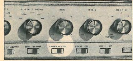
Well, we seem to have covered everything-except for the question of styling. This is very much a matter of personal taste, but whether you prefer a simple, uncluttered control panel or one more like something from . an Apollo space rocket it should be functional. Knobs should not be too small to handle properly, switches should be positive and if knobs are inscribed with some indication of position, these indents must be near the panel marks to avoid parallax errors. Inscriptions should not be too small or use unduly fancy typeface so a magnifying glass is necessary to read it and knobs ought not to be too close together.
A recent trend is the use of slider units for some of the controls-usually for tone and balance. One advantage is that the actual positions can be seen from some distance away but many people find the old fashioned rotaries a little easier to use. It's a matter of opinion, because slide controls are used almost exclusively in recording studios-although they are invariably mounted in a horizontal plane. A final point concerns on/off switches: At one time it was always considered good design practice to mount these separately to avoid undue wear on the volume control. This is not so necessary these days and a combined control certainly helps to avoid a disconcerting blast of sound as soon as you switch on .. . .
Good Listening!
References
1. The influence of high order products In non-linear distortion, D. E. Shorter, Electronic Engineering, April, 1950.
2. Transistors for hi fi, Myers and Kahn, Electronics World, April, 1964.
3. Audio Quality, G. Slot , lllffe Books.
4 . Ibid.
5. Duration of attack transients of non-percussive orchestral instruments, Luce and Clark, AES Journal, July, 1965.
(Audio magazine, Apr. 1971)
Also see:
Fail-Safe Audio Amplifier Design (Feb. 1973)
Buying Watts and Other Things (Feb. 1973)
Intermodulation Distortion: A Powerful Tool for Evaluating Modern Audio Amplifiers (Feb. 1972)
Transient IM Distortion in Power Amplifiers (Feb. 1975)
FTC Power Ratings: An Optimistic View (Feb. 1975)
= = = =