
Manufacturer's Specifications
Power Output: 200 watts per channel continuous, 8 ohms, 20 Hz to 20 kHz; 300 watts per channel continuous, 4 ohms; 600 watts continuous into 8 ohms in bridged mode.
Rated THD: Less than 0.01% maximum, from 250 mW to rated power per channel, 20 Hz to 20 kHz.
Frequency Response: 10 Hz to 100 kHz, + 0,-3 dB, for 1-watt output.
S/N Ratio: Hum and noise, 100 dB below rated output, 90 dB IHF.
IM Distortion: Less than 0.01% from 250 mW to rated output, for any combination of frequencies from 20 Hz to 20 kHz.
Damping Factor: Greater than 100.
Input Impedance: 20 kilohms.
Input Sensitivity: Switchable for either 1.4 or 2.5 V.
Dimensions: Front panel, 16-3/16 in. (41.1 cm) W x 7 1/8 in. (18.1 cm) H; chassis, 143/4 in. (37.5 cm) W x 61/2 in. (16.5 cm) H x 14 1/2 in. (36.8 cm) D, including connectors.
Weight: 50 lbs. (22.7 kg).
Price: $1,850.
Company Address: 2 Chambers St., Binghamton, N.Y. 13903.
The McIntosh MC 2002 is a Class-AB solid-state stereo power amplifier rated at 200 watts per channel into 8-ohm loads. Physically, the unit is of average size for a Class-AB design, though somewhat lighter than former McIntosh amplifiers of this power rating because it has no potted output transformer or autoformer. McIntosh's massive and expensive bifilar-wound transformers gave them an edge on the competition in the tube designs of the 1950s. When solid-state designs came along, McIntosh used a different device, an autoformer, which used the same core but with a single winding of heavy wire that allowed impedance matching over a broad range.
The front panel sports McIntosh's traditional, rear-illuminated, black-glass construction with gold and black anodization and gold and teal-green nomenclature. The large, square power switch is the only front-panel control, and it glows red when activated. "Power Guard" indicators for each channel monitor clipping quite effectively; between them is a temperature indicator which signals when one or both channels have been shut down because of overheating. Two large, peak-responding power output meters, which use full-wave detection to respond to both positive and negative peaks, occupy the left and center of the panel.
On the rear panel are two RCA signal-input connectors, a screw-clamp barrier strip for the four speaker wires, an unswitched a.c. outlet rated at 100 watts or 1 ampere maximum, a 15-A line fuse, and slide switches for mono/ stereo operation and input-sensitivity selection. The line cord is non-detachable.
The chassis construction is an exercise in simplicity. The sides, front, back, top, and bottom are all moderate-gauge (0.048-inch) steel. Four vertical heat-sink extrusions, each containing four TO-3 case output transistors, are bolted to both bottom and top, thus strengthening the assembly. The single, massive power transformer is mounted just behind the front panel, its weight carried by a steel U-section that runs from side to side along the bottom plate. To either side of the transformer are the driver circuit boards. The chassis components are held together by self-tapping screws. The threads in the thin, steel panels were well-formed, but it would be easy to cross-thread the bolts on reassembly. The mounting holes in the heat-sinks are pre-tapped. All in all, this amplifier's mechanical construction is better than average for a home product in its price category.
The quality of the 11 glass-epoxy circuit boards in the McIntosh MC 2002 is very high. Boards are 1/16-inch, single-sided, with milled rather than sheared edges. Solder mask is used but there are no component designators; this should pose no problem, though, because the uncrowded layout allows easy component identification from a chart.
Component quality is good to excellent, although no Wonder Caps are used. The correct component types are used throughout, and bias and meter calibration trim pots are sealed from airborne contaminants. Parts are well-secured and run cool. This amplifier, in the McIntosh tradition, should provide 10 to 20 years of maintenance-free service.
Circuit Description
The circuit of the MC 2002 is unusually simple for such a high-performance amplifier. McIntosh's design philosophy is to achieve high performance with stability and reliability by using a simple topology, with selected components operating in their most linear range.
The input signal passes through an attenuator set at 0 or -5 dB by a rear-panel switch. It is then a.c.-coupled to one input of a differential amplifier stage. Negative feedback from the amplifier output is applied to the other input; output of this stage connects to a positive-drive, cascode-connected pair for further current and voltage amplification. This feeds a push-pull complementary, triple- Darlington, emitter-follower output stage. The final transistors are four positive and four negative TO-3 case devices per channel, with large (0.5-ohm) emitter resistors.
The power supply uses a single, oversized transformer, a 35-A bridge rectifier, and two 12,000-µF electrolytic capacitors, which have 77 joules of energy storage. The front-panel power switch actually controls the d.c. supply to a heavy-duty relay; this, in turn, switches on a.c. voltage to the power transformer's primary. The 16 output transistors are convection-cooled, eliminating potentially noisy fans from the design. Output voltage is ±80 V d.c. The metering and protection functions use as much circuitry as the basic amplifier path itself. A 2-S turn-on signal delay is provided by an input-shunting FET. The amplifier does not generate a transient, so its output is left free of series relay contacts. If a sustained d.c. offset is detected at the output, an SCR crowbar circuit shorts the power transformer's secondary and causes the line fuse to blow. The amplifier is protected from power-line surges by clamp components in the power supply. If the heat-sink temperature reaches 200° F, thermal cutout switches open and remove the-80 V supply to the driver boards, stopping bias to the entire channel. A volt-clamp limiting circuit also protects the output transistors.
McIntosh's proprietary Power Guard circuitry, a special feature of this amplifier, monitors the summing point at the input differential amplifier. The amplifier input and feedback signals are fed, respectively, into the noninverting and inverting inputs of the Power Guard amplifier/comparator. Any voltage difference here means that the overall negative feedback is inadequate to cancel distortion; this might occur from voltage clipping, current limiting, or slew-rate limiting. The sensed voltage is rectified by a bridge rectifier, filtered by a capacitor, and fed to an LED. The front-panel LED indicators, one for each channel, illuminate if distortion is present, causing reduced resistance in a light-dependent resistor. This photoresistor shunts just enough input signal to ground to eliminate the overdrive. In our use with music, only voltage clipping activated the indicators, confirming the high speed and current capacity of the MC 2002. The Power Guard circuit is nondefeatable.
Music waveforms are often "clipped" off because the owner may demand higher sound levels and higher voltages than the system can supply. Still, very few manufacturers offer true clipping indicators on their home amplifiers, though this feature is considered essential for professional audio work. We have tested a number of amplifiers that do not snip off the voltage cleanly and thus cause more distortion than necessary when overdriven. McIntosh does not have this head-in-the-sand attitude about the realities of electronic music reproduction. Even if we nitpick details of McIntosh's Power Guard circuit, it is much appreciated as a first-order solution to a common problem.
Measurements

Fig. 1--Characteristics of the Power Guard circuit. (See text.) The continuous
signal is 10 kHz, 50 watts into 8 ohms, to which a 1-kHz burst is added
so that the resulting signal is +10 dB re: 200 watts. Note that several
distinct stages occur. First, there are the horns due to clipping before
the circuit acts; next, with the strong signal still present, the gain
is reduced to below clipping. Finally, with the 1-kHz overdrive gone,
the circuit restores the 10-khz signal to proper level. (Scales: 20 mS
and 15 V per div.)
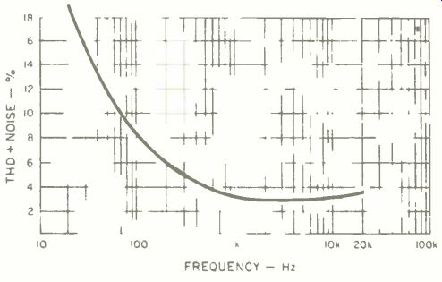
Fig. 2--Total harmonic distortion plus noise vs. frequency at 10 dB over
rated output into 8 ohms, steady-state, showing the effect of the Power
Guard circuit.

Fig. 3--Response to 300-Hz sine wave at 10 dB over rated 200 watts into
8 ohms. (Scales: 1.0 mS and 20 V per div.)
The McIntosh MC 2002 was first run for 1 hour at 33% of rated power, about 66 watts per channel into 8-ohm loads with a 1-kHz test signal. The chassis top became warm, but the amplifier didn't thermally shut down.
Voltage gain was measured to be 29.0 dB at the 1.4-V switch setting into an 8-ohm load; at the 2.5-V switch setting, gain was 23.8 dB. The IHF sensitivity for 1 watt into 8-ohm loads at 1 kHz was 2.82 V. Power output was measured into a variety of load conditions, as shown in Tables I, II and Ill. Using a rating of 0.1% THD, minimum continuous power output per channel was 220 watts (42.0 V) into 8 ohms and 333 watts (36.5 V) into 4 ohms. Bridged operation resulted in a mono signal with a minimum continuous power output of 757 watts (38.9 V). Setting the amp at rated output voltage, THD was 0.0071% for 8-ohm loads (40.0 V), 0.01% for 4-ohm loads (34.64 V), and 0.0044% (38.9 V) in bridged configuration.
The IHF signal-to-noise ratio, A-weighted re: 1-watt output into 8 ohms, measured 90 dBA for the right channel and 92 dBA for the left.
Crosstalk versus frequency was measured by driving one channel and measuring the leakage into the other, with the unused input terminated by a 1-kilohm resistor not connected to external ground. Crosstalk was found to be better than -68 dB from 20 to 500 Hz, rising to -48.4 dB at 10 kHz, and peaking to -42.0 dB at 20 kHz in the left channel. The left-to-right crosstalk is dependent on the load on the left channel; if one removes the load, the crosstalk becomes unmeasurable. This suggests grounding problems or that the long leads to the heat-sinks talk to the other channel.
The characteristics of the MC 2002's Power Guard circuit were measured using a special test setup. A 10-kHz signal was set to drive the amp at -6 dB (20.0 V, 28.28 V peak, 50 watts output). A lower frequency transient at 1 kHz was added such that the combined peak value was 10 dB greater than the rated continuous output (126.4 V, 179 V peak, 2,000 watts). Power Guard attack and release times were then observed from the signal envelope, as shown in the 'scope photo of Fig. 1; they proved to be of the "fast" (5 mS) attack, "slow" (50 mS) release variety. A normal amp would clip heavily, showing "horns" and a brightening outline on the trace for the duration of the 1-kHz added pulse, then would instantly (a good amp can recover quickly) put out the 10-kHz,-6 dB signal. Horns do appear briefly at the beginning of the overdrive pulse block in the 'scope photo, but vanish as the circuit acts quickly. When the overdrive is suddenly cut off, the signal collapses to an area smaller than baseline and gradually expands as the circuit action decays.
Is it better to clean up the clipping and sacrifice a "hole" in the following low-level signals for 50 mS, or to clip and instantly recover to play the low-level signals? Overall, the technique used in McIntosh's Power Guard seems best to us because musical transients do not end abruptly, actually allowing the circuit to recover as they die out. Also, the 5-mS attack time keeps the circuit from acting on extremely short overdrives. A "tick" cannot cause a 50-mS "suckout." Because of the action of the Power Guard circuitry, gradually increasing the overdrive causes a smooth increase in distortion, not the step function seen with most solid-state amplifiers. Beginning at 0.0018% at rated power (0 dB), the amp's THD rises to 2.2% at 4 dB overdrive, and 3.0% at 10-dB overdrive. Figure 2 shows THD + N for the audio bandpass, with the amplifier driven to 10-dB overdrive into 8-ohm loads. Distortion increases above 3.0% below 1 kHz, reaching a peak of 19% at 20 Hz under these conditions. Figure 3 shows the 'scope appearance of this 10-dB overdrive state at 300 Hz, and the waveform looks much more like a sine wave than would one produced of a conventional amplifier, which might deliver 40% THD + N, quite close to the perfect square waveform seen with 50% THD + N. Figure 4 illustrates the MC 2002's square-wave response at rated power, 200 watts per channel into 8 ohms at 20 kHz. Power Guard has been switched on, resulting in the tiny overshoot peaks at the leading edges. (These peaks are not seen before the Power Guard cuts in.) Adding a 1.0-µF capacitor causes minimal ringing of the output network, with a 0.2-dB increase in sine-wave output at 20 kHz, but no instability.
The 1-watt frequency response into 8 ohms showed the amplifier to be within ±0.1 dB from 20 Hz to 20 kHz. The high-frequency,-3 dB down point was at 100 kHz for the 2.5-V input position and at 250 kHz for the normal, 1.4-V input position.
The low-frequency damping factor was measured at 285 for 8 ohms and 143 for 4 ohms. The wide-band damping factor was measured at 53 for 8 ohms and 27 for 4 ohms.
The slew rate measured 23 V/µS up and 40 V/µS down (asymmetrical). IHF slew factor into 8 ohms was 4.0 (80 kHz); into 4 ohms it was 5.0 (100 kHz). Dynamic headroom measured 1.4 dB (42.3 V, 223.7 watts) at a pulsed clipping from a steady-state level of 200 watts rated power into 8 ohms; the 4-ohm IHF headroom was 1.7 dB (47 V, 552.3 watts). These figures indicate a power supply with medium voltage regulation.
Our new test of maximum output current utilizes a 20-mS pulse (repeated al a 0.5-S rate) driving one channel of the amplifier into a 0.1-ohm load. Under these conditions, the McIntosh MC 2002 delivered a 14.8-A rms pulse before clipping, showing itself to be average in terms of current delivery among high-powered amps on the market today. (For an explanation of the authors' test procedure, see "Short-Circuit Current Test" accompanying this issue's review of Sansui equipment.)

Table I-Power output per channel and distortion, 8-ohm loads.
Table II-Power output per channel and distortion, 4-ohm loads.
Table III-Power output and distortion, mono channel, bridged 8-ohm loads.

Fig. 4-Response to 20-kHz square wave at 200 watts into 8 ohms, Power
Guard circuit activated, with input increased to get 200 watts output.
(Scales: 10 µS and 20 V per div.)
The McIntosh's meters proved to have a VU-type action rather than the peak action claimed. A period of 0.4 S is required for the pulse to reach 50% power indication in the 20 Hz to 20 kHz range. At 1 kHz, steady-state signal measurements were accurate at 200 watts, with the error increasing to 127% as power output was decreased to the 2-watt level. With a 1-cycle pulse of 200 watts into an 8-ohm load, the meters read 20 watts at 20 Hz, 15 watts at 200 Hz, 8 watts at 2 kHz, and 0 watts at 20 kHz. In general, the Power Guard indicators served as true clipping monitors, often firing in the presence of minimal meter action.
Use and Listening Tests
Equipment used to evaluate the McIntosh MC 2002 included a Linn Sondek turntable with a Magnepan Unitrac 1 arm, Yamaha MC-1000 and Shure V15 Type V-MR cartridges, Meridian and Philips Compact Disc players, Mark Levinson ML-7 reference preamp, Mark Levinson ML-9 and Crown Micro-Tech 1000 solid-state power amps, and B & W 801F Special and Snell Type A/Ill loudspeakers. Controlled listening tests also were carried out with an ABX Co. comparator after matching outputs of the McIntosh MC 2002 with the ML-9 to within 0.001 V using the CBS STR-151 test record. New Monster Cable was used, with co-author Greenhill's usual X-Terminators removed so the cable's spade lugs would fit the McIntosh's speaker-connector barrier-terminal strip. (See "Comparator-Controlled Listening Tests," which accompanies this issue's review of Sansui components, for more details on the A/B/X double-blind testing procedure and the equipment used.) The MC 2002 was auditioned on the Snell Type A/III speakers. First subjective impressions with an amp can be misleading, as was the case here. Greenhill first detected a lack of highs, as well as a grain, glazed midrange and lack of textural detail on low-level sounds. After tightening all the speaker-wire connections, things improved greatly. The veils lifted, detailing improved markedly, and Greenhill became aware that the McIntosh's strong sonic suit was its soundstage rendition, spatial replication, instrument localization, and depth of field. The reference ML-9, though clearly brighter in the midrange and far more detailed in the highs, could not match the McIntosh's field depth. On the other hand, the Levinson outstripped the MC 2002 in deep bass, yielding more solidity and impact on CD bass-drum notes. The Power Guard lights flashed frequently during these bass tests, in which Greenhill subjected both amps to the biggest bass-drum whacks Telarc's CDs could deliver, but no audible clipping was heard from the MC 2002.
The MC 2002's limiter circuit was auditioned to determine if it would interfere with the amp's sonics by blunting transients or coloring the sound under near-clipping conditions.
We enlisted the help of B & W 801F loudspeakers, which feature their own protection circuits. Both the Levinson and Crown could be pushed into audible clipping, producing an awful shredding of the sound, whereupon the B & W's protection circuits cut in and temporarily shut off the speakers.
The McIntosh MC 2002's nondefeatable limiter allowed the amp to maintain its aplomb under the same overdriven conditions, and no shredding of sound was heard. The McIntosh's Power Guard prevented the amp from clipping and thus would protect a loudspeaker without the B & W's safeguards. Midrange transients were quick without being over-bright or steely, and deep bass transients had plenty of punch.
Below clipping, the MC 2002 again lacked vitality and air in the upper midrange while showing better than average depth of field. Bass definition was good to excellent, holding up well during Power Guard operation, but not going quite as deep as the Levinson. The Crown Micro-Tech 1000 proved to have a faster attack on transients than the 2002, but was brighter and zippier.
The controlled, double-blind A/B/X test failed to support these subjective sonic differences found during uncontrolled listening sessions. Using the B & W 801F speakers, Greenhill was able to identify the randomly selected amp in only 10 out of 16 trials, a rate which reaches only 68% statistical significance rather than the desired 95%. The McIntosh operated smoothly during all bench and listening tests. A slight turn-off pop could be heard in the speakers, but no turn-on thump was present. The A/B/X switching relays caused no problems with the McIntosh's protection circuitry, as it did with another amp being tested.
In summary, we find the McIntosh MC 2002 amplifier to offer good quality, high reliability and elegant engineering design. Co-author Clark was particularly impressed with the high performance achieved from the MC 2002's simple and relatively cost-effective circuit topology. The Power Guard circuitry, with its very desirable clipping indicators, is a well-thought-out design for preventing audible distortion and speaker damage from intense clipping. The controlled tests, however, reveal no significant sonic differences (below clipping) between the McIntosh and the reference ML-9 amplifier, confirming Clark's belief that well-designed amplifiers today differ little sonically. Greenhill's subjective impressions of the MC 2002, when it was inserted in the audio system described above, continued to be positive about the amp's spatial replication and critical of its midrange clarity-even when he couldn't document his reactions under blind, A/B/X-controlled conditions.
-Laurence L. Greenhill and David L. Clark
(Source: Audio magazine, Apr. 1985)
Also see:
McIntosh MC2600 Amplifier (Equip. Profile, Feb. 1992)
Link | --McIntosh MC 7200 Power Amplifier (Jan. 1990)
McIntosh Model C-27 Stereo Preamplifier (Sept. 1978)
Mcintosh Model MR-80 FM Tuner (Mar. 1981)
Sansui C-2301 Preamp and B-2301 Amp (Apr. 1985)
= = = =