Manufacturer's Specifications
FM Tuner Section
Usable Sensitivity: Mono, 9.3 dBf.
50-dB Quieting: Mono, 15.3 dBf; stereo, 38.1 dBf.
Selectivity: 68 dB.
Stereo Separation: 44 dB at 1 kHz; 36 dB at 10 kHz.
Amplifier Section
Power Output: 40 watts continuous per channel, 20 Hz to 20 kHz, 8-ohm loads.
Rated THD: 0.04%.
Frequency Response: High level, 20 Hz to 40 kHz, ± 1.0 dB; phono, RIAA ±0.2 dB.
SMPTE-IM Distortion: Less than 0.03%
Dynamic Headroom: 1.0 dB.
Damping Factor: 150 at 20 Hz.
Input Sensitivity: Phono, 2.0 mV; high level, 160 mV. S/N: Phono, 80 dB re: 5-mV input; high level, 95 dB re: rated output.
Phono Overload: 220 mV.
Tone Control Range: Bass, ± 10 dB at 100 Hz; treble, ± 10 dB at 10 kHz.
Subsonic Filter: -6 dB at 20 Hz, 12 dB/octave slope.
General Specifications
Price: $299.95.
Company Address: 680 Beach St., San Francisco, Cal. 94109.
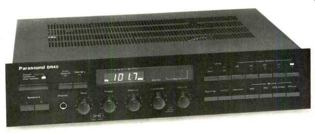
What can you get for under $300 in an integrated stereo receiver? In the case of Parasound's DR40, quite a bit of power, if that's what you're after-as much as 40 watts per channel, with some margin of reserve at mid-frequencies. On the tuner side, the DR40 offers frequency-synthesized AM and FM tuning; however, the sensitivity, distortion and noise performance may leave something to be desired if, like me, you seek the absolute ultimate in FM performance.
As to controls, the DR40 has a true, separate loudness control, something you rarely find in receivers costing much more than this one. The frequency-synthesized tuning system here also gives you up to five AM and five FM presets, for instant recall of your favorite station frequencies. And then there are the standard, but essential, items, including bass and treble controls and the usual number of program-source inputs (with the high-level pair glamorized by silkscreened panel designations that have been changed from the familiar "AUX" to the now-fashionable "CD/Video").
Still, the DR40 is very much a budget-priced receiver; thus, there's only so much you can expect from it. In some respects, it delivered more than I had expected, while in others it fell short.
Control Layout
A "Power" on/off pushbutton at the upper left of the all-black front panel is augmented by a two-color LED (green for normal operation and red for a short-circuit or overload condition). Immediately below are a pair of speaker-selector buttons, while to the right are a tuning-mode switch (manual or automatic scanning) and a "Memory" switch, used in conjunction with the five station-preset buttons located just across the panel. In the manual tuning mode, pressing the "Up" and "Down" buttons (located alongside the presets) increments tuning in 50-kHz steps for FM or 10-kHz steps for AM. Near the uppercenter of the panel is the station-frequency display, with a single LED to show whether a received signal is in stereo and a five-LED signal-strength indicator. The latter uses two red LEDs for weak signals, an amber LED for marginal signals, and two green LEDs to show strong-signal conditions.
Along the lower edge of the panel are a stereo-headphone jack plus rotary controls for "Bass," "Treble," "Balance," "Loudness," and "Volume." I was pleased and surprised to find a variable loudness control on such an inexpensive unit. Normally, loudness compensation is tied to the volume control on low-cost (and even some expensive) receivers, making it difficult, if not impossible, to adjust this circuit for proper compensation at low listening levels. With the separate, rotary loudness control, you can adjust "Volume" to preferred listening levels and then adjust "Loudness" to boost bass response just enough for perfect auditory compensation. Pushbuttons below the row of presets and "Down"/"Up" tuning buttons handle program selection, control the single tape-monitor circuit and mono/stereo operation, and activate the subsonic filter.
The rear pane is equipped with 300- and 75-ohm FM antenna terminals, an external AM antenna terminal, a hinged AM ferrite-rod antenna, the usual pairs of input and tape-output jacks, a ground terminal, two sets of color-coded speaker terminals, a pair of a.c. outlets (one switched, the other unswitched), and a main fuse-holder. A battery holder, also on the rear panel, is designed to hold a pair of AA batteries. These serve as backup for the preset memory if there is a power failure or if the unit must be disconnected from the a.c. supply for any reason. I'd have welcomed the aesthetic touch of even a cheap plastic cover over the battery compartment, but since it is on the rear panel it will usually be out of sight.
Tuner Measurements
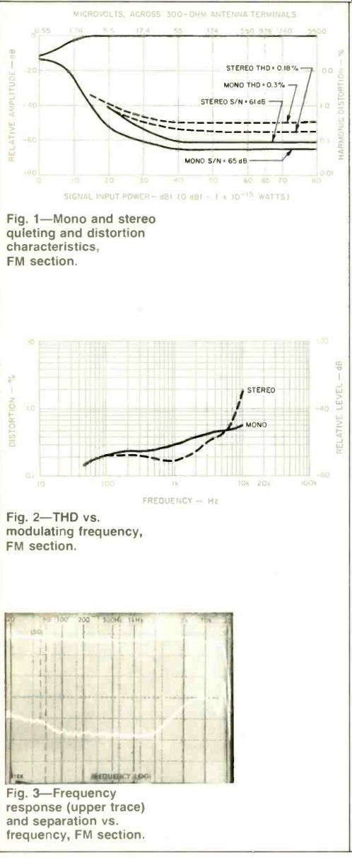
Fig. 1--Mono and stereo quieting and distortion characteristics, FM section.
Fig. 2--THD vs. modulating frequency, FM section.
Fig. 3--Frequency response (upper trace) and separation vs. frequency, FM section.
Although the owner's manual is only a fold-out brochure the equivalent of eight pages in length, two of these pages are dedicated to a full schematic diagram. From it, I surmised that the FM circuit is fairly basic, employing an FET r.f. stage and bipolar oscillator and mixer stages. I.f. and multiplex-decoder functions are handled, by and large, by multi-purpose ICs. The minimal amount of circuitry may account for the DR40's average FM performance.
Usable sensitivity in mono fell short of the claimed 9.3 dBf, measuring 12.0 dBf. Stereo usable sensitivity was governed by the stereo threshold, which was about 15 dBf. I found that 50-dB quieting in mono occurred with a signal strength of 18 dBf; in stereo, the 50-dB quieting figure of 26.0 dBf was actually much better than claimed. The most disappointing aspect of the FM tuner section's performance was its signal-to-noise ratio, which, even with strong signals, never exceeded 65 dB in mono or 61 dB in stereo. Figure 1 shows how signal strength affects signal-to-noise ratios as well as harmonic distortion (for a 1-kHz, 100%-modulated signal) in mono and stereo. In mono, THD measured 0.3%, but in stereo it was actually somewhat better, measuring only 0.18%.
Harmonic distortion as a function of frequency, for mono and stereo operation, is plotted n Fig. 2. Frequency response of the FM section was flat within ± 1.0 dB from 30 Hz to 10 kHz, but it was down 5.0 dB at 15 kHz.
The 'scope photo of Fig. 3 shows overall frequency response and stereo separation as a function of frequency. I measured stereo separation as 38 dB at 1 kHz, 37 d3 at 100 Hz, and 27 dB at 10 kHz. Capture ratio measured 2.5 dB, and alternate-channel selectivity was 65 dB. I.f. and spurious rejection were better than 80 dB, while AM suppression measured 50 dB.
Figure 4 shows the crosstalk and distortion components that appear in the unmodulated (right) channel when a 5-kHz test signal is used to moculate the opposite (left) channel. The tall spike at the left is the desired 5-kHz left-channel output signal; all the components to the right are either distortion components or subcarrier components appearing at the output of the unmodulated channel. The number and amplitude of these unwanted products are greater than I have encountered in tests of any other tuner or receiver within recent memory; however, a letter received from Parasound just as I was completing this review indicates that distortion may well be lower in later production runs.
Frequency response for the AM tuner section (whose circuitry consists largely of a single IC) is shown in Fig. 5. Response was down some 6 dB at around 2.5 kHz, referred to 1 kHz. This is about what I have come to expect from most AM tuner circuits found in low- to mid-priced receivers and even in a few high-priced models. Some designers of these circuits argue that increasing the AM bandwidth would result in annoying whistles and interference beats, especially at night, due to the crowding of the AM band in the United States and some other areas. I suppose that's true, but it is also true that, as a result, the AM section of this receiver-and of many others with similar AM circuitry sophistication-delivers sound that is no better than and sometimes inferior to what you can hear from a table model or hand-held radio.
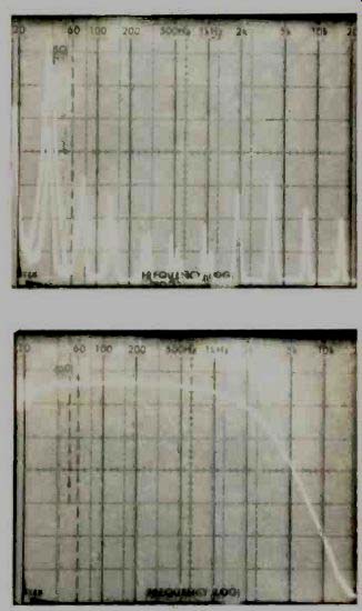
Fig. 4--Crosstalk and distortion components for a 5-kHz, FM modulating signal.
Fig. 5--AM frequency response.
Amplifier Measurements
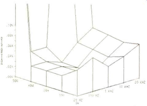
Fig. 6--Power output vs. frequency vs. THD.
The power amplifier section was able to deliver its rated power (40 watts per channel into 8-ohm loads) and then some, at all frequencies from 20 Hz to 10 kHz. At 20 kHz, THD rose a bit higher than the claimed 0.04%, to 0.07%. At mid-frequencies, maximum power output for the rated THD of 0.04% was 50 watts. A three-dimensional plot showing distortion as a function of power output and frequency is presented in Fig. 6.
Damping factor measured 100, using a 50-Hz test signal and referred to an 8-ohm load. Dynamic headroom measured 1.2 dB, a bit better than the 1.0 dB claimed by Parasound. I measured three types of IM distortion for this receiver. At rated output, SMPTE IM was 0.3%, decreasing to 0.05% just below that output level. CCIF IM, using twin tones at 19 and 20 kHz, was 0.01%. This form of distortion takes into account only the 1-kHz "difference" signal generated by the two high-frequency test signals. IHF IM, on the other hand, takes into account all intermodulation components in the spectrum up to 20 kHz, and, as you can see from Fig. 7, there were many such distortion components, generated at 1-kHz intervals from around 4 to 20 kHz.
Calculating their equivalent percentage, the IHF-IM distortion figure turned out to be a rather high 0.65%-higher than I would have expected from just the THD and SMPTE-IM numbers recorded earlier.
Preamplifier Measurements
Phono input sensitivity, referred to 1 watt of output, measured 0.35 mV, while 20 mV was required to produce 1 watt of output via the high-level ("CD/Video" or tape) inputs.
Frequency response for the high-level inputs was flat within 1.0 dB from 4 Hz to 40 kHz and within 3 dB out to 80 kHz.
Although RIAA equalization of the phono preamplifier circuitry was accurate to within 0.5 dB at the high end, I observed a deviation from the RIAA curve of -3.1 dB at 50 Hz. It is possible that the 'designers of this preamp circuit tailored its response to the modified curve proposed by the IEC (International Electrotechnical Commission), with its extra low-end roll-off, rather than the official RIAA curve.
Phono overload, though acceptable at 100 mV for the standard 1-kHz signal, fell far short of the 220 mV claimed by Parasound, who don't say what frequency they used to check phono overload. The EIA Amplifier Measurement Standards, which I use, call for this important parameter to be measured at a test frequency of 1 kHz. By using a higher test frequency (say, 2 kHz or even higher), Parasound could have achieved their higher overload figure. If that's what they did, then they should have said so. But, as I say, the DR40's performance here is acceptable.
Hum and noise for the phono circuits was a satisfactory 75 dB below 1-watt output, referred to a 5-mV input signal at 1 kHz. I measured 79 dB of signal-to-noise ratio for the high-level inputs, again referred to 1-watt output, this time with 0.5 V of input signal applied. Turning the volume control all the way down resulted in a further reduction of noise output, down to -81 dB below 1-watt output.
Figure 8 shows the maximum boost and cut range of the bass and treble tone controls, while Fig. 9 shows the bass-boost curves that can be obtained at various settings of the separate loudness control. The subsonic filter, when activated, resulted in an attenuation of 4.2 dB at 20 Hz.
Fig. 7--Distortion products from the IHF-IM twin-tone test using 19and 20-kHz test signals.
Fig. 8--Tone control characteristics. Vertical scale: 10 dB/div.
Fig. 9--Bass boost for several settings of the variable loudness-compensation control.
Use and Listening Tests
There is much about the Parasound DR40 that is commendable. Certainly, a 40-watt-per-channel, all-in-one receiver that sells for less than $300 represents an achievement in itself. Frequency-synthesized tuning in such a low-cost, relatively high-powered receiver is also very worthwhile. On the other hand, I was disappointed by the inability of the FM tuner section to deliver even 70-dB signal-to-noise ratios (the minimum that I consider acceptable for today's program sources, with their dramatically increased dynamic range). After all, many FM stations are now playing CDs with increasing regularity, and, with a good tuner, the advantages of CDs are immediately apparent. Here, their quiet background will be marred if the tuner's signal-to-noise ratio is marginal.
If you keep the volume control at safe levels and don't try to push this receiver's amplifier section too hard, the high intermodulation distortion levels which I noted on the test bench don't become a disturbing factor. In fact, at moderate listening levels the amplifier sounds quite good-again raising the age-old question concerning the relevance of measured distortion under static, test-signal conditions. Push the amplifier a bit harder, though (as you would do with medium-to-low-efficiency loudspeakers), and the slight graininess associated with dynamic forms of intermodulation distortion becomes subtly apparent. Used with efficient speakers in a moderate-sized listening room, the amplifier section will do reasonably well. In strong-signal areas, FM will also be acceptable, especially if you keep volume levels low enough so that background noise remains below the threshold of audibility.
All in all, the DR40 does represent quite a lot for its price, but-in the last analysis-in audio equipment you still get what you pay for.
-Leonard Feldman
(Source: Audio magazine, Apr. 1985)
Also see:
Revox B215 Cassette Deck (July 1985)
Parasound D/HX-600 Cassette Deck (Equip. Profile, Mar. 1988)
= = = =