Manufacturer's Specifications:
Frequency Response: 0.3 Hz to 160 kHz, +0,-3 dB; 1 Hz to 40 kHz, + 0,- 0.2 dB.
THD: 0.002%.
Rated Input/Output: 2.0 V.
S/N Ratio: 110 dB.
Third-Octave Filters: 33 in each channel, at standard ISO frequencies from 16 Hz to 25 kHz.
Q Factor: Constant 4.3.
Boost/Cut Range: ± 12 dB.
Input Impedance: Unbalanced, 20 kilohms; balanced, 600 ohms or 40 kilohms.
Output Impedance: Unbalanced, 10 ohms; balanced, 50 ohms.
Maximum In/Out Level: 8 V.
Dimensions: 17 1/2 in. W x 6 5/16 in. H x 14 11/16 in. D (44.5 cm x 16 cm x 37.3 cm).
Weight: 26.4 lbs. (12 kg).
Price: $5,450.
Company Address: c/o Madrigal Audio Laboratories, P.O. Box 781, Middletown, Conn. 06457.
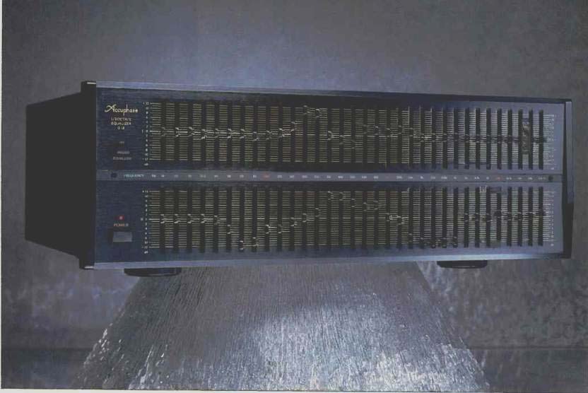
The Accuphase G-18 is an uncommon product for audiophiles in that it is a third-octave equalizer, something more likely to be found in sound-reinforcement systems. It has 33 filters on ISO frequencies for each channel-a very useful three more than the typical third-octave unit. The two extra filters at the low-frequency end are at 16 and 20 Hz, and the added high-frequency filter is at 25 kHz. For the best control of music now available on CD, equalization adjustment may be quite necessary below and/or above the normal range of 20 Hz to 20 kHz.
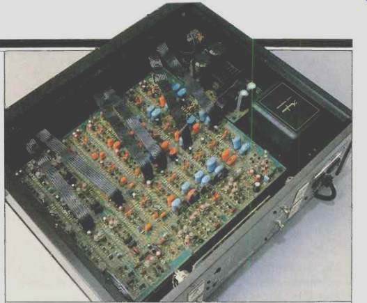
Accuphase states that the filters have a constant third-octave bandwidth with a Q of 4.3. A claimed advantage is that interference between filters does not increase with changes in the level-control settings. The manufacturer uses discrete components to gain substantial improvement in sound quality. There are a total of 706 transistors, eight FETs, and just 10 ICs. The buffer and the bandpass-filter amplifiers are configured as differential, complementary push-pull circuits.
The G-18 is one of the relatively few units that have balanced inputs and outputs; these can keep noise pickup to a minimum and eliminate troublesome ground loops. The impedance of the balanced inputs can be switched either to 600 ohms to match some professional-type equipment or to 40 kilohms for minimum loading on the source. There are also phono-jack inputs and outputs for unbalanced connections to typical systems. The G-18 does not have connections for a tape recorder, something which almost all other audiophile equalizers include. Accuphase states that not having these additional external connections ensures the purity of the signal path.
The G-18 uses a proprietary filter circuit with separate power-transformer coils for the left and right channels. This greatly reduces the possibility of interaction between channels when adjustments are made. An acrylic protective panel is provided; it is easily installed or removed, and protects the equalizer from inadvertent shifting of the filter settings.
Control Layout
The Accuphase G-18 is immediately impressive because of its physical size and weight. The 6-inch-high front panel, with its 66 filter sliders, is not easily ignored. The left-channel sliders are on the top half of the panel, and the right-channel ones are below. Each slider adjusts smoothly and has a soft but definite center detent. The total travel is 13/4 inches, which makes for easy, accurate adjustment. The panel is marked with horizontal lines for every dB of boost or cut; these are located between all sliders and at the scale ends. There are numbers every 2 dB, with the "dB" designation at the bottom of each scale. Filter frequencies are shown on a horizontal gray band across the center of the front panel, between the two filter sections. The labels for "100," "1k," and "10k" glow in a gentle red that helps to guide the user to particular filters.
A small pushbutton to the left of the upper filter section selects "Off" or "Equalizer." The button is black, and there is no LED status indicator, so on the black version of the G-18, which I had, it is difficult to be certain of the switch's position from a distance. With the optional champagne-gold front panel, the button would stand out better. The power switch and its red LED indicator are at the lower left of the panel. All panel designations are white and are easy to read even in fairly dim light; markings on the gold version, which I have not seen, are black. The steel top and bottom panels are perforated to ensure good ventilation.
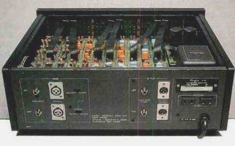
The inputs are on the left of the rear panel. The two "Unbalanced" inputs use unusually rugged phono jacks.
The "Balanced" inputs use three-pin, XLR-type, female sockets. To their right, slide switches select "Unbalanced" or "Balanced," and "600 Ohms" or "40k Ohms" impedance for the balanced inputs. The unbalanced input impedance is 20 kilohms.
The outputs are on the right center of the panel, and the XLR-type connectors for the balanced outputs are male in this case. The output impedances are labeled "10 Ohms" for unbalanced and "50 Ohms" for balanced. The choices of connectors, configurations, and impedances on the G-18 are outstanding. Two unswitched a.c. outlets, with a total capacity of 200 watts, are at the right end of the rear panel.
I removed the top cover to get a better view of the p.c. board which covers most of the chassis area. As I was looking at the layout, I realized that this board was for the left channel only and that another board was below a separating, isolating metal plate. The good-sized, fully enclosed power transformer- on one side of the top board was quite warm to the touch after several hours of operation, but it was not hot enough to burn the fingers. The boards and the components on them are of excellent quality, and all parts are neatly labeled. Boards at the back of the front panel are for the sliders; a connection board is at the back.
Soldering was excellent, and there was basically no flux anywhere, even on the hand-soldered points. Inter-board connections were made with multi-conductor cabling, with sockets and plugs for the most part. Ground wiring was heavy gauge, something I had never noticed in equipment examined previously. The chassis was rigid and rugged.
Overall, I judged this Accuphase equalizer's construction to be of the highest quality I have seen to date in audiophile components.
Measurements
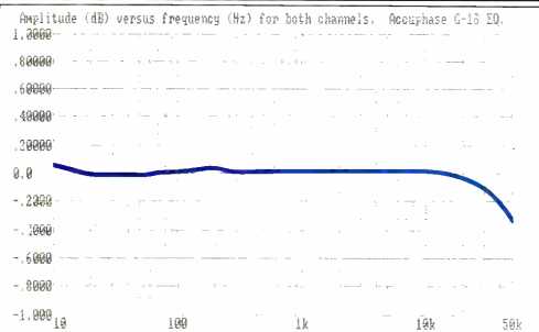
Fig. 1--Frequency response with EQ in and filter sliders at their center
detents. Note the expanded vertical scale of 0.2 dB/div.
Because the G-18 has filters above and below the normal audio band, I set my Audio Precision System One test gear to check frequency responses all the way from 10 Hz up to 50 kHz. Figure 1 shows the very flat response when EQ was switched in but all filters were at their center detents. Specific results were -0.01 dB at 20 Hz and -0.04 dB at 20 kHz; the -3 dB points were at 2.6 Hz and 160 kHz. Figure 2 shows the responses for each of the 33 filters at maximum boost and maximum cut as well as the results with all filters set at their extremes. A close examination of Fig. 2 confirms that the maxima are very consistent and that the center frequencies are accurate. The frequency of the 1-kHz filter's response peak was 1,015 Hz, which is just 1.5% high.
Figure 3 presents the responses that resulted from boosting and cutting combinations of adjacent filters (listed in the caption). The 2-dB steps were set by eye, but there does generally appear to be a bigger change between +2 and +4 dB than for the other steps. The filters have relatively little effect on the response outside their immediate areas, which is good; however, the ripple in the frequency response with the multiple filters is higher than desired at settings of +4 dB and above.
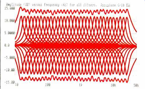
Fig. 2--Frequency response of each filter section at maximum boost and maximum
cut and of all sections combined at maximum boost and cut.
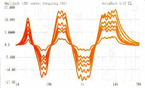
Fig. 3--Frequency response of various filter combinations, set in 2-dB steps
from zero to maximum (12-dB) boost or cut. From left to right: 25-Hz boost;
63- and 80-Hz cut; 200-, 250-, and 315-Hz boost; 800-, 1000-, 1250-, and
1600-Hz cut, and 4-, 5-, 6.3-, 8-, and 10-kHz boost.
I first checked for THD + N from 20 Hz to 20 kHz to 2 V, and the plot was a straight line just above 0.001%. I concluded that distortion was down under the noise. Figure 4 is the result of repeating this test but with the level increased to 5 V. Over a good part of the band, the results are less than 0.0007%. You can see a little jump in the left channel at around 60 Hz and two jumps in the right channel at around 5 and 16 kHz. I'm not certain if these high points were caused by filters slightly out of exact zero, but even if they were, the results are marvelous. Figure 5 shows THD + N at 1 kHz for increasing voltage. Below 2 V, the measured THD + N is controlled by noise. The actual distortion does not exceed 0.001% until both channels are driven to almost 9.5 V. Clipping did not appear anywhere from 20 Hz to 20 kHz, until 11.8 V.
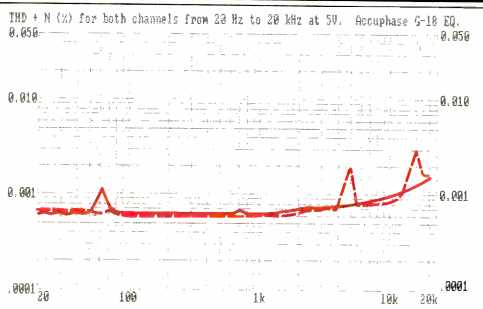
Fig. 4--THD + N at 5 V out, well above the rated output voltage, is still
quite low. Note slight distortion peaks at around 63 Hz in the left channel
(solid curve) and at about 5 and 16 kHz in the right (dashed curve); see
text.
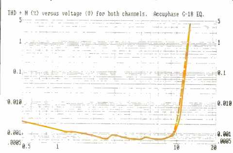
Fig. 5--THD + N vs. output voltage at 1 kHz for left channel (solid curve)
and right (dashed curve). Elevation of curves at low voltages is due to noise.
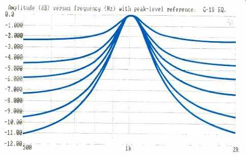
Fig.
6--Bandwidth of 1-kHz filter for boost settings from 0 to +10 dB, in 2-dB
steps. Curves have been normalized to peak at 0 dB; see text.
To get a good look at filter shape with increasing amounts of boost, I took an expanded look (Fig. 6) at the response of the 1-kHz filter while increasing boost in 2-dB steps. The peak-reference mode of the Audio Precision System One plotted the six sweeps with all peaks at the 0-dB reference, which helps in finding the bandwidths (-3 dB points) and in comparing filter shapes. A Q of 1.0 (with a bandwidth of 1.4 octaves) is the maximum possible for good assurance that there will be no ringing. A one-octave bandwidth has a Q of 1.4, which usually is quite acceptable even in critical listening. A filter with a third-octave bandwidth has a Q of 4.3, which is much more likely to ring when hit with a transient.
Frankly, I am not a fan of constant-Q equalizers, particularly when they are relatively narrow band, such as third-octave. I was glad to see that the GT18's filters are not that constant in Q, even though the manufacturer states that such a design is a virtue. Figure 6 shows that a Q of 1.4 (-3 dB at 720 Hz) would be reached with a boost of about 3 dB. The Q gets close to 4.3 (-3 dB at 904 Hz) at a boost of 7.5 dB or so. An operational caution, therefore, would be to avoid boosts approaching 7.5 dB, if at all possible.
The S/N ratios, referred to 1 V, were 103.4 dB with a bandwidth of 22 Hz to 22 kHz, 102.9 dB with CCIR/ARM weighting, and 105.8 dB with A-weighting. Using Accuphase's 2 V rated output as the reference would increase all of these results by 6 dB. The output polarity is the same as the input.
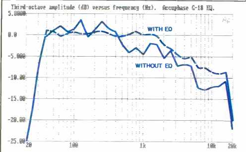
Fig. 7--Third-octave response of a loudspeaker before and after equalization.
Note that frequency balance and smoothness have improved, but equalization
cannot extend the low bass.
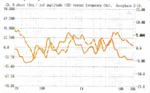
Fig. 8--Relative phase (solid curve) and frequency response (dashed curve)
of G-18 with equalization used in Fig. 7. Phase, in degrees, can be read
from left-hand scale.
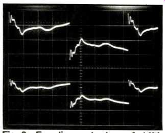
Fig. 9--Equalizer output with 119-Hz, 0.8-V square-wave signal. Top waveform
shows the results of using the equalization in Fig. 8; note the ringing.
Bottom waveform shows results of shifting all 33 sliders down about 2 dB
in order to reduce ringing without changing relative frequency response;
see text. Horizontal scale: 1 mS/div.
Use and Listening Tests
The owner's manual has good instructions on connecting the G-18 to other equipment. The options are more limited than with most equalizers because the unit does not have tape in/out connections. Occasionally the language is a bit clumsy, which obscures some of the valid points being made. It is true that all of the filters are at ISO standard frequencies, but it is also true that the frequencies are standard for acoustical analysis, not for musical reasons.
The G-18 does cover the entire band, plus a little extra, with its 33 filters per channel. This calls for a third-octave RTA for guidance in making response connections. Adjusting a third-octave equalizer from start to finish by ear can lead to many bad choices and can waste a lot of time. I assume that, considering the G-18's price, Accuphase dealers will help buyers adjust this equalizer for the best overall response. However, the manual should say much more on this subject than what is contained in a couple lines of general reference.
Figure 7 shows the before and after responses of a JBL 4411 loudspeaker. Response adjustments were made with the help of an Ivie IE-30A third-octave RTA. The before-EQ response was rough, and there was an erratic roll-off of the higher frequencies. I started by pulling down the 63-, 125-, and 250-Hz peaks. After that, I worked on making the display the way I wanted it, boosting and cutting for a flat response out to almost 2 kHz, with a roll-off above that point.
The scale settings for the filters used were:
+6 dB at 16 Hz, +5 dB at 20 Hz, +4 dB at 25 Hz, + 3 dB at 31.5 Hz, 0 dB at 40 and 50 Hz,-4 dB at 63 Hz, + 0.7 dB at 80 Hz, +1 dB at 100 Hz, -4.5 dB at 125 Hz, +3 dB at 160 Hz, -0.8 dB at 200 Hz, -3 dB at 250 Hz, -0.3 dB at 315 Hz, -3 dB at 400 Hz, +2.2 dB at 500 Hz, +3.4 dB at 630 Hz, +2 dB at 800 Hz, +4 dB at 1 kHz, 0 dB at 1.25 kHz, +0.7 dB at 1.6 kHz, + 3.2 dB at 2 kHz, -3 dB at 2.5 kHz, + 3.5 dB at 3.15 kHz, -1.3 dB at 4 kHz, 0 dB at 5 kHz, +4.4 dB at 6.3 kHz, +4 dB at 8 kHz, +1.2 dB at 10 kHz, +2.1 dB at 12.5 kHz, +0.4 dB at 16 kHz, -0.3 dB at 20 kHz, and 0 dB at 25 kHz.
There was no doubt about the great improvement in the low-frequency/high-frequency balance and the smoothness of the sound with pink noise. I wondered what the actual response of the equalizer was after all these adjustments and how phase varied with frequency. Figure 8 shows the response was generally boosted rather than cut below 50 Hz and above 400 Hz. Phase deviations remained within ±35°. Reexamination of Fig. 7 convinced me that the boost in the lowest frequencies had been ineffective in extending the speaker's low-bass response. (To do this, a subwoofer would be in order.) Listening to a variety of CDs led me to believe there was a little unwanted ringing.
Because I was only using one channel for this testing and listening, it was easy to set up an alternate equalization, which would cause less ringing on the other channel. A given boost setting causes more ringing than the same degree of cut, so I followed the same curve but with all sliders set 2 dB lower. This caused a 2-dB drop in the signal level with EQ in, but it maintained all of the response corrections and reduced the ringing. Long-term listening satisfaction was then possible with all types of music. This result emphasizes that there is more to equalization than making the response flat. The top waveform in Fig. 9, made through the channel that was set for the first-try EQ, shows obvious ringing at several of the boosted frequencies. The bottom waveform shows the reduction in ringing and overshoot after all slider settings were lowered by 2 dB.
At this point, let me put in a caveat about equalizers in general and third-octave units in particular. Be careful about trying to do too much with an equalizer. A common failing among users of third-octave equalizers is in trying to get the "perfect" flat display on an RTA, ignoring the other effects of the filter settings. This approach can lead to excessive boost and cut settings in an attempt to get the desired amplitude display, such as pumping in 10 dB of boost in order to fill an indicated 2-dB dip at the crossover frequency. Such excesses can actually cause great response deviations within a filter band and large phase shifts in the equalizer, as well as excessive ringing.
As far as possible, improve the sound with acoustical treatment of the room and with speaker location and aiming, to say nothing about the initial choice of loudspeakers. I have seen quite a few cases where users have boosted equalizers across the whole band as a form of gain control.
Do not do this; even octave-band equalizers will ring with excessive boost. With any equalizer, bring down the peaks instead of boosting the valleys. Be especially wary of trying to boost a deep dip such as that from a crossover. To correct broad response deviations, make most of your corrections, if possible, with the tone controls or the speaker's midrange and tweeter adjustments (which have low 0). Use EQ only to finish the smoothing. These constraints apply to the use of any equalizer but particularly to third-octave models. When used properly, the Accuphase G-18 delivers superb performance, with substantially no distortion or noise and a ruler-flat response when EQ is out. The 33 filters will all find their uses in quality installations, and the filters at the low end can smooth subwoofer response, a task at which most equalizers are not effective. The G-18's balanced inputs and outputs may be of great benefit, and perhaps essential, both for high-end audiophile systems and for professional uses. The price is very high, but the quality is impeccable.
-Howard A. Roberson
[adapted from: AUDIO/Apr. 1989]