
by C. G. McPROUD
The Boeing 747 is a BIG plane, and TWA has employed a multiplexing system to provide passenger entertainment facilities with a minimum of wire and great savings of weight.
JUST IMAGINE how much wire would be required to "pipe" fiftween channels of audio to each of the 342 seats on TWA's new 747's, letting each listener choose which of the programs he wanted to hear. In the conventional way, this would involve some 800 pounds of wire, in addition to hundreds of connections to the switches. TWA-the most experienced airline in passenger entertainment--does it in a different way.
They do it by multiplexing. And to effect a further saving in wiring, they also multiplexed the passenger service facilities-individual lighting and hostess calling-and the overall saving in weight is of the order of 500 pounds Publicity on the 747 has made everyone aware of just how big the ship is-an overall length of 231 feet 10 inches, a wing span of 195 feet 8 inches, and a height of 63 feet 4 inches at the tail. It has a maximum takeoff weight of 710,000 pounds, of which 112,500 pounds is payload.
There are 12 rest rooms, six galleys, seven portable beverage dispensers, and five complete movie theatres in each 747-three of which show general pictures, while the other two feature "mature" films. You choose your seat by selecting the picture you want to see.
In addition to the movie sound tracks, ten additional sound programs are provided to each of the seats, several of which can be stereo. The fifteenth channel is provided for override of announcements from the captain or from the hostesses in the three sections of the tourist compartment and the two in the first-class compartment. Another system provides a series of multi-lingual "canned" announcements at the hostess' selection.
The 747 has room, and it also has some sophisticated electronics to accommodate the needs of the 58 first-class and the 284 tourist-class passengers. One has to see the 747 to believe it.
Multiplexing
To make it possible to transmit fifteen channels of information over a single pair of wires, multiplexing is resorted to. In the past, multiplexing was accomplished primarily by frequency-division--that is, each program modulated a specific carrier frequency, and all were combined in a wideband output. The individual programs were sorted out much in the same manner as one selects any one of many AM broadcast stations on the air at once.
Because of the possibility of r.f. interference with the navigation and communication requirements of air travel, another means was used in the 747, and this method is known as Time Division Multiplexing. This is accomplished by switching sequentially from one channel to the next at a rapid rate--in this case, 26,000 times per second.

Fig. 1--Simplified block diagram of the main multiplexer and waveforms
showing how it functions. Fig. 2 (right)--The main multiplexer alongside
a pack of cigarettes to show size.
There are several different forms of Time-Division Multiplexing-pulse--amplitude modulation (PAM) , which transmits one pulse per sample with the amplitude of each pulse proportional to the amplitude of the sample.
Pulse-width modulation (PWM) transmits one pulse per sample and varies the duration of each transmitted pulse in proportion to the amplitude of the sampled input. Pulse-position modulation (PPM) transmits two pulses for each sample-a reference pulse and a data pulse, with the time elapsed between the reference pulse and the data pulse being proportional to the amplitude of the sampled input. Pulse coded modulation (PCM) transmits a series of pulses for each sample. The pulses represent a binary number, and the magnitude of the binary number represents the amplitude.
PCM is the only one of the four methods which is truly digital, and thus independent of amplitude. Since this is the case, the system can employ a threshold below which noise cannot affect the output, and it is only necessary that the pulses be just above the threshold. Therefore it is possible to re-establish the pulses without increasing the noise in the system simply by adding amplification. This provides an immunity to all sorts of problems in addition to noise-mismatches, imperfect connection resistances, stray reactances. The system results in minimum radio-frequency interference, ease of maintenance, simpler cabling and installation, and higher quality of transmission.
Creating the PCM signal involves a device known as the multiplexer which commutates the inputs sequentially, samples and holds them at the level of the sample at the time of the sampling, converts the analog signals into digital pulses, and then combines the result with the sync-pulse generator to feed the transmission line.
In the TWA entertainment system--which was developed by ISC-Telephonics Division of Instrument Systems Corporation (which is, by the way, the parent company of Benjamin Electronic Sound Corporation as well as some forty other subsidiaries) employs a zone system of distributing the program material throughout the plane. This is necessary because of the different series of programs which must be fed to the various compartments. The output of the main multiplexer is fed to two zone multiplexers in the first-class cabin, and to three additional zone multiplexers in the economy cabin. While the main music programming is fed throughout the plane, separate sound-track programs must be fed to the five "theaters," and it is at the zone multiplexers that the outputs from the five projectors are introduced to the inputs of the separate zone multiplexers. The various outputs are then fed to the separate cabins. At each seat group is a separate demultiplexer controlled by the switches in the passenger arm rests, and the two or three outputs from this demultiplexer are fed to the passenger headphone amplifiers. The demultiplexer receives the PCM signal from the zone sub-multiplexer, converts it to an analog which is a PAM (pulse amplitude-modulated) signal, then commutates it to select the desired program and filters out the products of the multiplexing process before feeding it to the passenger headphone amplifier. Bear in mind that some of the fifteen channels are used in pairs for stereo programs while the remainder-including the PA system program and the movie sound track--for the section being fed--are mono. Thus it would be possible to have two stereo programs, for example, together with six mono channels fed into the main multiplexer, with the PA and movie channels fed into the zone sub-multiplexers along the plane. Since each passenger is provided with stereo phones (the transducers are in the arm rests, and their acoustic outputs are fed to the passengers' ears through paired plastic tubing), two separate amplifiers are required for each of the 342 seats. These amplifiers--150-mW solid-state units--are located at each seat position.
The entire electronic system for passenger entertainment is solid-state, naturally, and we are told that there are about a million transistors per plane, give or take a few thousand.
These are not discrete transistors, of course. Some of the large-scale integrated circuits have as many as 800 transistors on a single clip.
Multiplexer Functioning
To go into more detail of the operation of the multiplexer, refer to Fig. 1 which shows the waveforms present when the system is sampling only two audio signals-Input 1 and Input 2.
The vertical dashed lines represent the actual times of sampling the individual inputs. At the first sample,. input 1 is positive, and of low amplitude. This is shown in the waveform at the "sample and hold" device as a straight line of the amplitude of the input at the time of sampling. The next sample is taken from input 2, as directed by the commutator, and this results in another "step" in the sample-and-hold waveform. The commutator again directs the sample to be taken from input 1, and another step is shown, also a positive value. The next sample is again from input 2, and this time the audio wave is negative, and this shows up as a negative step in the sample-and-hold wave.
The analog-to-digital converter now produces a series of pulses which indicate a digital number corresponding to the amplitude of the s-&-h waveform.
These pulses are then combined with the sync-pulse-generator output and fed through the line driver to the transmission line.
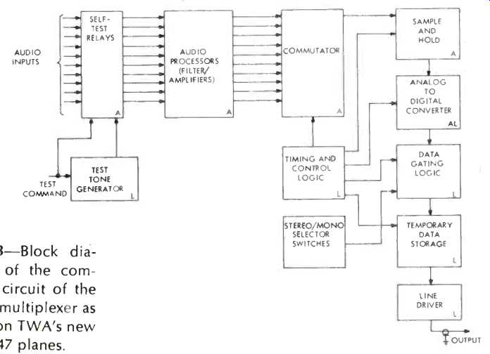
Fig. 3--Block diagram of the complete circuit of the main multiplexer
as used on TWA's new 747 planes.

Fig 4--Block diagram of a zone multiplexer. Five of these are used on each plane, and they combine the main signal with those which are unique to the particular zone-Stewardess PA, and the movie sound track.

Fig. 5--Passenger seat demultiplexer, where the digital line signal
is converted to analog form and the individual program is selected by
the passenger.
The main multiplexer is shown in more detailed block-schematic form in Fig 3. The 12 audio inputs are fed into the "self-test" relays, of which more later, and thence into the audio filter/amplifiers, or processors, which shape the audio signals to conform to the system requirements. The outputs from the processors--still 12 in number are then channeled to the commutator which samples them sequentially and delivers the sample amplitudes to the sample-and-hold unit, so it now has a waveform in a series of steps which represent the amplitudes of the 12 signals at the time of sampling, and these series are repeated 26,000 times per second, as directed by the timing and control logic.
The output from the s-&-h unit feeds the analog-to-digital converter, which is also under the control of the timing unit, and it generates a series of pulses for each of the steps, depending on the amplitude of each step. This digital signal now enters the data gating logic where the stereo "tags" are added onto the odd numbered channel of a stereo pair so as to indicate that the next higher even numbered channel is paired with it for stereo. Any odd-numbered channel may be paired with the next even numbered channel to produce a stereo pair. The signals finally feed the line driver, and thence the transmission line.
The transmission line is, of course, a coaxial cable, as one can determine from a consideration of the frequencies involved. For instance, there are 26,000 samples per second. These are converted in the analog/digital device to as many as four pulses per sample, and each pulse has a positive and a negative transition. Therefore, we have a minimum of 2 x 4 x 26,000, or some 208,000 "changes" in polarity. If we are to maintain a reasonably sharp waveform-that is, with well-defined pulses-we usually consider that we need about ten times the frequency of the pulse, so we are somewhere in the vicinity of 1 to 2 MHz, at least. Thus we enter the zone sub-multiplexer a number of other audio signals which are unique to the zones in the plane. These include the movie sound tracks and the zone PA system from the hostess. These new audio signals have to be processed in just the same manner as in the main multiplexer to result in a digital signal before they are added to the output of the main multiplexer to feed the passenger electronic de-multiplexers. This involves some reshaping of the original line signal, and the interweaving of the two digital signals. The output of the zone unit is then fed to the seats in the particular zone, and the input from the main multiplexer is multiplied onto the next zone, where the same process is repeated. There are five separate zone sub-multiplexers on each TWA 747, and each is of the configuration shown in Fig. 4.
The zone outputs feed all of the seat electronic units one strip of three-seat modules, and three strips of two-seat devices. These de-multiplexers, shown in Fig. 5. accept the signals from the zone multiplexers, separate out the digital "0" and "1" signals, and feed them to the seat logic modules where the stereo and PA over-ride "tags" are introduced.
The resulting outputs are fed to another converter-this time a digital-to analog unit-and thence to the Mosfet module,, which might be termed a "de-commutator," in that it picks out the desired portion of the amplitude modulated signal at the command of the seat selectors-two or three, depending on the string of seats in which the demultiplexer is located. (There are three seats in each group in the string along the left side of the plane, two strings of two-seat groups in the center, and one string of two-seat groups along the right side, of the plane. There are two aisles running the full length of the plane, making for easy movement of passengers.) The seat electronics de-multiplexers feed the separate pairs of headphone amplifiers, and thence drive the transducers. These are similar to hearing aid earpieces, and are built into the seat control unit which accommodates the 12-position program selector switch, a dual volume control, the overhead reading-light control, and the hostess call button. The acoustic outputs from the transducers are fed to the passengers' ears through the plastic tubing mentioned before. The typical seat control unit is shown in Fig. 6, which is the type used in the first-class section by TWA. A wide variety of control units is available, so no two airlines will lave exactly the same type-a matter of decor, undoubtedly-but they are all similar, and all perform the same functions.
In addition to the passenger entertainment system just described, another complete multiplexing system is employed on the 747 to provide for passenger services, without the need for large numbers of wires. These services are less demanding in frequency response, but work on a similar principle at a considerably slower rate.
If a passenger wants his reading light on, he pushes a switch button. This action places a "1" on his seat position time slot, and as the many seat groups are scanned, the "1" causes an SCR in the overhead unit to fire and light his reading lamp. Similarly he can signal the stewardess, using another time slot. All of this makes it possible for the stewardess to turn on all reading lights or turn them off simultaneously without the necessity of running the numerous wires that would be necessary if each circuit had to be of the same configuration as the "two-way" switching in our homes.
Self-Test
The "self-test" feature mentioned previously makes it possible for a maintenance man to test all of the systems in the plane in about fifteen minutes. He simply energizes the self test circuits, and proper functioning is indicated by some chosen method, such as a flashing of reading lights.
The method is to disconnect all the usual inputs to the main multiplexer and feed each channel with a tone.
This test tone is multiplexed and pulse coded and then distributed to all the seat electronics units, where it is de multiplexed and reconstructed as an audio signal, and has thus passed through the entire passenger entertainment system. A similar system tests the passenger service system, making it unnecessary for a maintenance man to go to each seat and try out everything-a job that would take several hours for the 342 seats.
Space Requirements
In spite of all each unit performs, none of them is large. The main multiplexer is about 3 x 4 x 19, and is shown with a pack of cigarettes alongside it in Fig. 2. The passenger seat electronics unit is about 5 x 6 x 2, and accommodates the entertainment and service electronics in this small package. The zone sub-multiplexer is about 4 x 8 x 12, and the entire multiplex system (exclusive of tape player, movie projectors, and the PA system)
weighs about 250 pounds, resulting in a net saving of the previously mentioned 500 pounds. The system requires about 5 kW of power, but that is a fairly simple problem since each of TWA's 747s has four 60-kw generators feeding 110/220-V, grounded neutral circuits.

Fig. 6--Passenger's control unit, located in the seat armrest. Program
selection, volume, reading light, and hostess call button are provided
here, as well as control for reclining seat back and the new "lumbar" inflatable
cushion for support to the passenger's lower back area.
Program Sources
The numerous programs are recorded on tapes which are played from open-space "cassettes-that is, there are no reels, but the tape feeds into the cassette, weaves back and forth in whatever space it can find, and finally comes out the other side to feed past the head, leaving room for more tape to enter the cassette.
The housing for the cassette player is shown in Fig. 8. and is located in the compartment under the floor of the passenger compartment. This space is simply loaded with electronic gear--radio equipment, radar equipment, navigation computers, passenger address audio, and so on.
The Movie Projection system
Fig. 7--Movie projector swung down from the overhead for servicing.
9600 foot reel provides four hours of continuous picture.
Each of the five movie projectors can be loaded with film long enough to play continuously for four hours, using a reel about three feet in diameter working on the same principle as the common 8-track cartridge. That is, the film comes out at the center of the reel and is fed back onto the reel on the outside, thus being "rewound" as soon as one showing is complete.
Figure 8 shows one of the projectors lowered from the overhead for servicing or changing the film. Four hours of 16-mm film means about 9600 feet of film, which accounts for the large reels. The hand of one of the maintenance men is shown at the lower right of the projector in the figure.
Performance
After all this, your question is certain to be, "How does it sound?" Surprisingly good, believe it or not. The tight coupling between the soft rubber pads and the passengers' ears makes for excellent bass response, and the high end extends to above 8 kHz. System frequency response is flat from 70 to 10,000 Hz, and the tape players maintain a ±3-dB tolerance. The movie screens are quite large and accommodate wide-screen pictures. The flutter is audible, but not worse than theatre movies,. of 1935, for example.
But you don't have to listen on the TWA 747s if you don't like the music and don't want to hear the movie. You can just sit there and eat if you wish.

Fig. 8--Amid a whole array of electronic equipment under the floor are
the main multiplexer (left center) and the tape reproducer (right center).
Below it is the main PA amplifier which feeds the 61 Jenson speakers.

Fig. 9--Grouped around the main multiplexer are two junction boxes,
zone multiplexers, and seat demultiplexers. Each is packed with solid-state
printed-circuit boards, as might be expected considering the complexity
of the circuits involved.

Fig. 10--Some idea of the spaciousness of the 747 can be gleaned from
the above. Nine seats across, the economy cabin is 20 feet wide and has
two aisles.

Fig. 11 (left)--William Gasper indicates hostess control panel for lights
and call signals. Above are the multilingual control for programmed announcements,
and the "boarding-music" control panel.
Historical
TWA has a long history of passenger entertainment, starting with their first demonstration flight with sound on December 7, 1960. This was done with very little fanfare, but proved so popular that it was introduced regularly with a press flight in July, 1961. The hollow-tube "headset" was introduced in 1964 because there was a large loss of the usual earphone units. People seemed to think they were legitimate souvenirs. (They still carry off many of the hollow-tube units. One wonders what they do with them when they get them home and try to plug into their hi-fi sets.) Stereo has been offered as regular fare since 1965, and now in the 747s you have your choice of 12 programs and two movies.
The writer is deeply indebted to TWA and ISC personnel for much of the information presented, and in particular to Charles C. Zambello, Manager-TWA In-Flight Entertainment, and William Gasper, Supervisor-Air craft Electrical Development, and for much of the technical information about the multiplex systems to J. Schachter, Vice President, Commercial Systems, ISC/Telephonics, whose seventeen years of experience in microwave systems and related equipment qualify him as an excellent teacher.
==========
(adapted from Audio magazine, May 1970)
Also see:
= = = =