
MANUFACTURER'S SPECIFICATIONS:
FM SECTION:
IHF Sensitivity: 2.0 µV or better.
S/N: 65 dB. THD: Less than 0.5%, mono or stereo. IM: Less than 0.5%, mono or stereo. Drift: 50 kHz maximum.
Frequency Response: 20 Hz to 15 kHz, ±1 dB.
Capture Ratio: 2.0 dB or less.
Selectivity: 55 dB or more.
Image Rejection: 70 dB or better.
IF Rejection: 100 dB or better.
Spurious Response Rejection: 90 dB or better.
Stereo FM Separation: 40 db @ 400 Hz; 35 dB @ 50 Hz.; 30 dB @ 10 kHz.
AMPLIFIER SECTION:
RMS Power Output (per channel, both channels driven): 60 Watts @ 4 ohms; 50 Watts @ 8 ohms; 30 Watts @ 16 ohms. THD: less than 0.5% from 20 Hz to 20 kHz at all power levels up to rated power. IM Distortion: Less than 0.25% up to and including full power output. Frequency Response: ±1 dB from 20 Hz to 20 kHz at indicated flat tone control settings.
S/N: Phono: 57 dB, ASA "C" weighting: High Level Inputs: 75 dB, "C" weighting.
Input Sensitivity: Phono: 2 to 5 mV (adjustable) for full power output; High Level Inputs: 200 mV for full power output.
Damping Factor: 8 to 20 @ 4 ohms; 16 to 40 @ 8 ohms; 32 to 80. (Lower figures at 20 Hz, higher figures from 75 Hz to 20 kHz.)
GENERAL:
Dimensions: (Less wood cover) 16 3/8 in. W. 5 1/2 in. H x 11 3/8 in. D.; With wood cover: 17 3/8 in. W. x 6 in. H. x 11 5/8 in. D.
Suggested Retail Price: $420.00 with black aluminum cover. Optional oiled walnut cover: $20.00.
With the introduction last year of the Model "A" integrated amplifier (Reviewed in Audio, Nov. 1969), Acoustic Research Inc. seems to have established a design philosophy which it has carried over into its new entry, a complete FM Stereo Receiver. The format seems to be to provide a basic, honest design which meets or exceeds all its specifications and leave out all "unnecessary" frills, gimmicks, seldom used controls, and soon.
There will be those who will differ with this approach, but there will also be others who will appreciate the uncluttered, almost austere front panel of this receiver, shown in Fig. 1. A long, narrow but well illuminated dial scale, including the usual stereo indicator light and a center-of channel tuning meter plus a good-sized tuning knob occupy the upper half of the flat, gold anodized aluminum front panel.
The dial scale is absolutely linear (every MHz is equidistant from its "neighbor," while the tuning knob is coupled to a weighted flywheel which provides what has to be the smoothest tuning action we can ever recall having tested! The lower half of the panel contains a three position selector switch (Phono, FM, and "Special," or high-level inputs), dual-concentric clutch-type bass and treble controls for individual tone control adjustment of left and right channels, a mode switch concentrically mounted with a balance control, and a master volume control which also serves as the power on-off switch in its most counterclockwise position. In addition, there are three "rocker" type switches which provide tape monitoring (or, tape playback input directly to the main amplifier section), muting on and off, and speakers vs. headphone selection. The lower right corner of the panel is equipped with a stereo headphone jack. That's all there is on the front panel. It is obvious that the engineers at AR felt that they preferred to provide outstanding performance at a price of $420.00 and elected to omit features offered by competitors, either because they felt they were not needed or because it would have boosted the selling price above desired target.
There is one feature found on the AR receiver control panel which is both novel and useful. The mode switch, in addition to having settings for mono and stereo operation, has a position called "null," which is used to balance aurally the two electrical output signals more accurately than can be done by "standing mid-way between the two loudspeakers." We first saw this circuit in early stereo amplifiers of the late nineteen-fifties and thought it was a good idea then. While other manufacturers never chose to incorporate it, AR has made it a feature of both their integrated amplifier and this particular receiver design. Here's how it works. When the mode switch is set in the NULL position, one input channel is reversed in phase, with unity amplification. It is then combined with the other channel and the combination is fed to both receiver outputs. If the input signals are identical except for amplitude, a sharp reduction in loudness is obtained through cancellation when the balance control is correctly adjusted. Obviously, a monophonic source of program material must be used in order for this circuit to work properly and the NULL circuit cannot compensate for two speakers of different efficiencies, but in our tests, it proved to be quite effective in establishing correct electrical balance, particularly when we fed tape-recorded material to the receiver, in which the two recorded channels were originally recorded at somewhat different levels.

Fig. 2-Rear panel view
A view of the rear panel of the AR Receiver is shown in Fig. 2. Speaker fuses, FM antenna strip, left- and right-speaker terminal strips are located at the left, while inputs and outputs for tape, the adjustable phono input level control and a chassis ground terminal are located at the right. All input and output connections are color coded, which is useful only if you happen to own AR turntable equipment and AR-supplied speaker cables. While spacing between "hot" and ground speaker terminals is adequate, the type of terminal used is the simple "wire wrapped under the screw" type, which has led most other manufacturers to use barrier terminal strips or other "short proof" types even if their output circuitry is protected against "dead shorts," as is the case with this receiver. A power line fuse and two convenience a.c. receptacles (one switched, the other unswitched) complete the rear-panel layout. The black aluminum cover supplied as standard equipment on the AR Receiver ( the walnut cover is a three-sided affair that fits over the existing metal enclosure) is a one-piece weldment which, when removed, discloses a rugged and sensible electrical and mechanical layout, as shown in top-side and under-side views of Figs. 3a and 3b. A completely sealed FM front end features FET's and a four section variable capacitor. The i.f. section features integrated circuits and a multi section crystal filter. Special audio circuits include a d.c. driver-clamping circuit to provide clean clipping and recovery from overloads. With power switch OFF, a special idler supply takes over to eliminate turn-on pulses and "pops." Besides the speaker fuses mentioned earlier, each channel is equipped with a self-resetting thermostatic circuit breaker. A total of seven printed-circuit modules are used in the receiver, and output devices are mounted on massive finned heat sinks which were only comfortably "warm to the touch" after hours of our laboratory testing with low-, medium-, and high power outputs. The driver stage is a little unusual in that it uses push-pull drivers with a transformer. Figure 4 shows the basic circuit. C1 prevents d.c. being applied to the transformer primary and R1, C2 form a high-frequency "step" circuit. The main feedback loop is applied via R2, C3 from the speaker output back to the emitter of the first transistor.
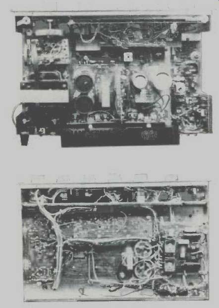
Fig. 3a--Top chassis view; 3b--Underneath view
Electrical Measurements
Important FM characteristics measured with respect to the AR Receiver are shown in Fig. 5. IHF sensitivity was exactly 2 µV, as claimed and full limiting (1 dB) took place at a very low 1.75 µV. Ultimate signal-to-noise ratio, reached at a signal input level of about 20 µV, was 65 dB, conforming nicely to published "specs" once more. THD in mono ( and, more significantly, in stereo) was 0.5%. Stereo separation, shown in Fig. 6, exceeded 40 dB (and the limits of our test equipment) at mid-band, and maintained a level of at least 30 dB all the way from 50 Hz to 10 kHz-about the best we have ever measured. The muting control (which AR chooses to call a "hush" control) was overcome by signals having an amplitude of between 5 and 7µV, but since listenable signals of as low as 3 and 4 µV were received in our listening tests, the mute defeat switch is a necessary front-panel control for those wishing to listen to such "fringe" signals. The mute threshold is not adjustable by the customer. The extremely linear FM detector response is shown in the 'scope photo of Fig. 7.
Because of the excellent performance of the amplifier section of this receiver, we decided to plot THD for a single channel with both channels driven as well as with only one. The results are shown in Fig. 8. With both channels driven, THD reached rated 0.5% at 53.8 watts, well above published claims. With only a single channel driven, power output attained was 57.6 watts for the same 0.5% distortion. The similarity between these two power-output extremes indicates that the power supply is very well regulated.
IM distortion, also plotted in Fig. 8 (for both channels driven) reached 0.25% at an output power of 51 watts. More importantly, neither IM or THD exhibited any rising characteristic at lower power outputs-a failing common with some solid-state designs. Readers may note the absence of the usual Power Bandwidth curve in this report. Its absence is a credit to the AR receiver for, quite honestly, our equipment only goes down to 10 Hz and up to 40 kHz, and at these frequencies, the AR receiver was not only able to supply "half power" as defined in Power Bandwidth Measurements, but just about full rated power at under 0.5% THD. We have to presume, therefore, that the actual power bandwidth (not stated by AR) actually extends below 10 Hz and above 40 kHz, making the actual end figures rather academic! Tone-control range is plotted in Fig. 9 and is seen to be completely symmetrical about the zero axis at both high and low ends. Frequency response was flat within 0.5 dB from 10 Hz to 30 kHz with tone controls set to mechanical center, while channel balance within 3 dB was maintained at all settings of the master volume control down to 65 dB below maximum.
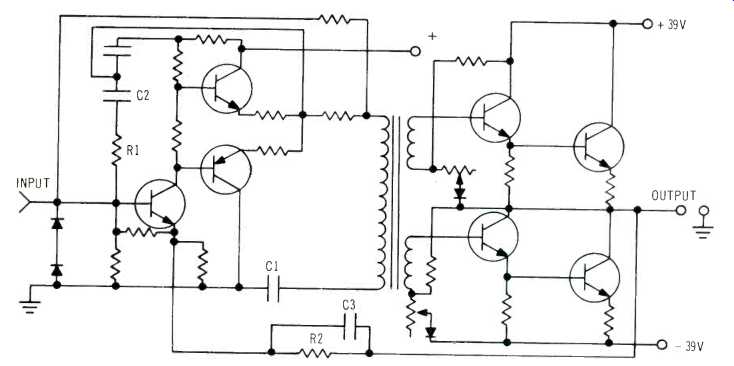
Fig. 4-Basic circuit of driver and output stages
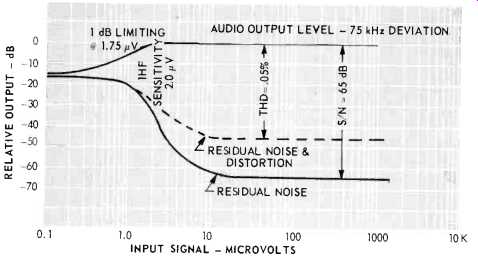
Fig. 5-FM characteristics
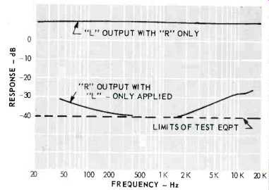
Fig. 6-Stereo separation
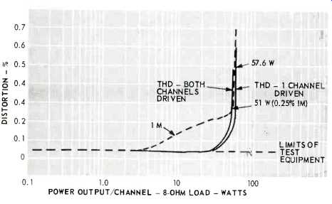
Fig. 7-THD and IM characteristics
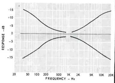
Fig. 8-Tone control curves
Listening Tests
The AR Receiver demonstrates its more-than-adequate reserve power at all dynamic levels, when auditioned with our low-efficiency speaker systems. Transparency of sound and good transient response were in evidence throughout our listening tests-so much so that we regretted the lack of multiple switching facilities for a second pair of speakers which this receiver could easily drive. Of course, a second set of speakers can be added with external speaker switching facilities, if desired, but this is one nicety that we feel could have been incorporated without destroying the "simplistic" approach inherent in the AR's external design philosophy. A third-channel output is provided, by the way, but it is for use with an additional power amplifier, not for direct use with a third, center-channel speaker.
In our FM listening, with indoor dipole, we managed to pick up 43 usable signals with the "hush control" turned off. With this control actuated, the number was reduced to 36, indicating that at least 7 stations had been previously received at signal levels of 7 µV or less and were still very listenable. Transferring antenna terminals to our out-door directional Yagi array, the number of stations received increased to 54, with no attempt made to rotate the antenna for even more stations which would undoubtedly have been satisfactorily received. Calibration was just about perfect, despite the expanded and linear scale.
Summary
The Acoustic Research FM Receiver offers more than its $420.00 worth of honest performance and it will appeal to those who favor high distortion-free power with a minimum of controls.
L. F.
(Audio magazine, May 1970)
Also see:
AR-7 loudspeaker (Equip. Profile, Feb. 1973)
Acoustic Research AR-6 Loudspeaker System (Jan. 1972)
AR (Acoustic Research) AR-7 loudspeaker (ad, Feb. 1973)
AR M1 Speaker (Equip. Profile, Jan. 1992)
Acoustic Research AR98LS Speaker (Jan. 1985)
AR (Acoustic Research) MGC-1 loudspeaker (ad, Nov. 1986)
Acoustic Research LST Speaker System (Dec. 1972)
= = = =