MANUFACTURER'S SPECIFICATIONS
POWER AMPLIFIER SECTION. IHF Music Power: 122 Watts @ 8 ohms; 1 95 Watts @ 4 ohms. Continuous (rms) Power, Both Channels Driven: 40 Watts/channel @ 8 ohms; 50 Watts/Channel @ 4 ohms. Power Output Over Entire Audio Range (20 to 20,000 Hz): 37 Watts/channel @ 8 ohms, both channels driven. THD: Less than 0.5% at rated output. IM Distortion: Less than 0.5% at rated output. Power Bandwidth: 10 Hz to 60 kHz. Damping Factor: 40 (at 8 ohms, 1 kHz). Frequency Response: 7 Hz to 80 kHz ± 1 dB. Input Sensitivity: 500 mV.
PREAMPLIFIER SECTION. THD: Less than 0.1 % at rated output of 500 mV. Frequency Response: 10 Hz to 20 kHz, +1 dB. Input Sensitivity: Phono 1 & 2, 3 mV; Mic, 2.7 mV; AUX, 200 mV; Tape Monitor and Tape Rec 1 & 2, 200 mV. Bass and Treble Tone Control Range: +10 dB at 100 Hz and 10 kHz. Muting Attenuator:-20 dB. Hum and Noise (IHF): Phono, Better than 85 dB; Aux, Better than 95 dB.
FM TUNER SECTION. IHF Sensitivity: 1 .8 µV. Maximum S/N: 70 dB. IHF Selectivity: Better than 70 dB. THD: Mono, less than 0.3%; Stereo, less than 0.5%. Capture Ratio: 2.0 dB. Image Rejection: Better than 85 dB. I.F. Rejection: Better than 100 dB. Spurious Rejection: Better than 90 dB. Am Suppression: 50 dB. Stereo Separation: Better than 40 dB @ 1 kHz. SCA Rejection: Better than 50 dB.
AM TUNER SECTION. IHF Usable Sensitivity: 10 V. IHF Selectivity: Better than 35 dB. Image Rejection: 80 dB. I.f. Rejection: 75 dB. S/N: 50 dB.
GENERAL SPECIFICATIONS. Power Consumption: 270 watts, maximum.
Dimensions: 19-1/16 in. W. x 5 1/8 in. H. x 15 3/8 in. D.
Weight: 30 lbs., 14 oz.
Retail Price: $349.95.
The "feature" that first impressed us about this good-looking medium-priced receiver from Pioneer was the very complete nature of the specifications listed by them and is shown above. More and more, reputable manufacturers in the industry are beginning to tell the "whole story" in their spec sheets and, in our view, that can only help them in the long run-providing the "whole story" is told with complete honesty, as it is in the case of this receiver. After long years of trying to follow the vague methods of the "package console" mass producers, our high fidelity component people are finally realizing that their customers are knowledgeable and perceptive. We are particularly impressed with the statement regarding "continuous rms power from 20 to 20,000 Hz at rated THD." It is possible that very soon the Federal Trade Commission will force all purveyors of sound equipment to adopt similar factual statements, but until that happens, it's nice to know that "our" manufacturers have voluntarily taken the lead in this respect.
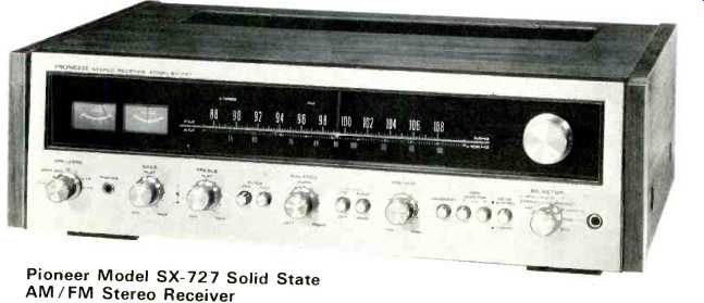
As for the receiver itself, the photo of the front panel layout shows that Pioneer has retained its familiar "look." The walnut cabinet is part of the package and, if it is removed for custom installations, the two walnut end-panels flanking the soft gold and black front panel make for a very rich looking unit. The large blacked-out dial area lights up in a soft blue when power is applied, and besides an expanded dial scale there are two signal meters and a series of illuminated words which light successively as the selector switch is rotated, indicating program source. The stereo FM light is also located in this line of lights, above the dial scale. The upper portion of the panel also contains the large tuning knob coupled to an effective flywheel. The "business" end of the panel is all arranged in a straight row across its bottom. Starting at the left, the power ONN/OFF switch does double duty as a speaker selector switch and, since there is provision for three pairs of speaker systems on this receiver, available positions of the switch include SPEAKERS A, B, C, A+B and A+C as well as a SPEAKER OFF position when only the headphone jack, located alongside the switch, is used.
The dual BASS and dual TREBLE controls, which come next, employ a unique feature which we have only encountered on separate integrated amplifiers to date. Although the controls themselves are continuously variable, "click-stops" have been included so that as you rotate the control for boost or cut, you can feel finite steps or stops (each worth about 2 dB of boost or cut at 100 Hz for the bass control and at 10 kHz for the treble control). This makes for easy resettability and gives the controls a very professional "switch" feel. The rear knobs (which control right channel tonal compensation) can be rotated separately, if desired, and they do not have the "click stop" feature. When the front knobs are used to adjust tone of both channels simultaneously, however, the clutch action of the two-section controls insures that the increments of boost or attenuation are equal, with respect to left and right channels. Very clever indeed! There follow Low and HIGH filter push-push switches, a BALANCE control, FM MUTING ON/ OFF switch and a matching AUDIO MUTING switch which, when depressed, lowers volume level by precisely 20 dB. This feature is beginning to appear on many receivers and is useful if you're listening is interrupted (say, to answer a phone) and you want to temporarily lower the listening level but restore it later to a pre-set point without having to alter the master volume control setting. Our only argument with Pioneer has to do with their choice of nomenclature. The word "mute," to an audiophile, has come to mean "FM mute"-or dead silence, but this is of small concern once you know what the button does. The master VOLUME control comes next, followed by more push-push buttons for LOUDNESS, a pair of TAPE MONITOR facilities, and the stereo-mono MODE switch. A seven-position program-selector switch and a microphone jack complete the picture. We rather wish that Pioneer had provided a pair of mic jacks (for full stereo live recording) rather than having the single mic input feed both channels monophonically; no additional circuitry would have been required just a slight change in switch wiring and another mic jack.
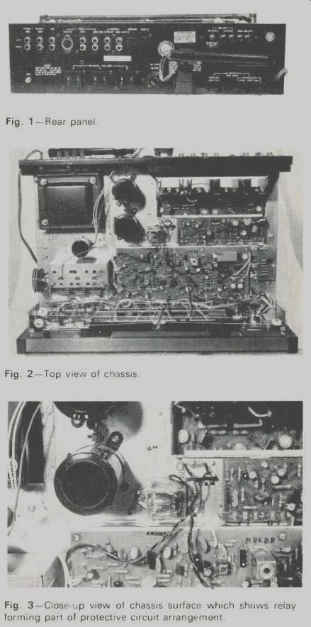
Fig. 1-Rear panel.
Fig. 2-Top view of chassis.
Fig. 3-Close-up view of chassis surface which shows relay forming part of protective circuit arrangement.
You may have noted that power amplifier and preamplifier specifications were quoted separately for this receiver. The reason for this becomes apparent as you examine the rear panel of the receiver, shown in Fig. 1. The small black "jumper block" at the right of the rows of input and output jacks connects PREAMP OUT jacks to MAIN AMP IN jacks. By removing this block, the unit can be considered as a separate preamplifier and amplifier, with all attendant advantages, such as the assembling of a multi-amp system with electronic crossover, etc. For those contemplating the addition of a four channel decoder and extra amplifier, this makes for a nice place to "insert" the decoder and leaves both tape monitor systems available for use in tape monitoring! Besides the usual signal input jacks, antenna terminals (for both 75 and 300 ohm transmission lines), switched and unswitched convenience a.c. receptacles, line fuse, AM antenna bar, and DIN recorder connector, special note should be made once again of Pioneer's unique speaker connection method, which seems to be theirs alone. Three polarized receptacles (one for each pair of speaker systems with which the receiver can be used) appear on the bottom section of the rear panel. Each receptacle accepts two polarized plugs, which are supplied in an accessory envelope (six in all). Your speaker wires are connected to these plugs which contain a red dot next to one of the prongs to help you phase the speaker connections properly.
Once you've got all the speaker wires wired to all the little plugs, you simply connect the plugs to the "left" and "right" portions of the chassis receptacles (they only go in one way) and you are assured of proper phasing. This may seem like much ado about very little the first time you make the connections, but wait till you want to move your system for cleaning, connecting other speakers, relocating of components, etc.
All you then have to do is unplug the speaker plugs which remain as part of your speaker cables. When you're ready to reconnect, just pop them back into their receptacles and you're "in phase" and all set to go once more.
Performance Measurements
As usual, we took a look at the "innards" of the SX-727 before putting it through its paces, and a view of the top surface of the chassis is shown in Fig. 2. Well-laid-out modular p.c. construction is used throughout, and there are separate modules for the FM front-end, the AM and FM i.f. section, the preamplifier, the tone control and switching stages, the power amplifiers, a special output protective circuit, and the power supply parts. The protective circuit connects to a two circuit relay, shown in the close-up view of Fig. 3. In addition to its "protective" function, this relay also delays connection to the speaker circuits for about two seconds when power is applied to the unit, effectively eliminating the "pops" or "thumps" associated with turn-on of many solid-state components. The FM front-end features a two-stage r.f. amplifier, of which the input stage is a FET. Ceramic filters and IC's are used in the FM i.f. section and an IC is used in the multiplex section as well. Tone controls are of the popular feedback type while the power amplifiers utilize negative and positive power supplies, facilitating direct coupling to the loudspeakers with no coupling capacitor required.
Performance
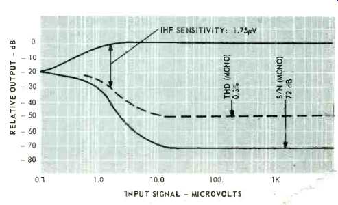
Fig. 4--Mono FM performance.
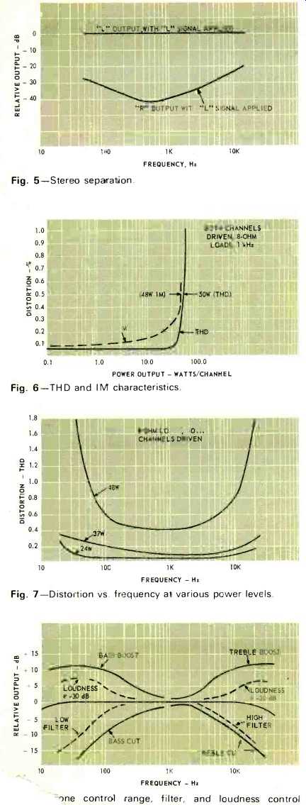
Fig. 5--Stereo separation.
Fig. 6--THD and IM characteristics.
Fig. 7--Distortion vs. frequency at various power levels.
Fig. 8--Tone control range, filter, and loudness control
FM performance equaled or exceeded published specs in just about every area. IHF sensitivity was 1.75 µV, as shown in Fig. 4. Ultimate S/N reached 72 dB, as opposed to the 70 dB claimed but, more importantly, with an input signal of only 5 µV, quieting was already better than 60 dB. Muting threshold is factory adjusted at about 6 µV and is "go-no-go," with no transitional distortion in evidence. With the muting switch on, therefore, that means that any station that defeats the mute circuit will be heard with a quieting of better than 60 dB. THD in both mono and stereo measured 0.3% and 0.5% exactly--as claimed and stereo separation measured 41 dB P at mid-band, with the rest of the separation characteristics plotted in Fig. 5. All spurious response figures were within spec although limitations of our measuring equipment can confirm an IF rejection figure only up to 90 dB so we can't verify the 100 dB figure quoted.
Since Pioneer was nice enough to detail all those lovely power output specs the way they did, we figured we had better take plots under all the conditions quoted. Thus, in Fig. 6 you can see our usual mid-band plot of THD and IM versus power output. Rated THD was reached at 50 watts per channel, as opposed to the 48 claimed while related IM was reached at a power output of just a bit below 48 watts per channel. The plots of Fig. 7, taken at various power levels versus frequency disclose that, indeed, the SX-727 cannot rightly be called a "48 watts per channel amplifier" at all audible frequencies, since low-frequency distortion at that power figure is excessive. Bear in mind, however, that Pioneer only rates the amplifiers as being capable of 37 watts per channel "across the board," and that is a nice, conservative figure--for at that power output, the highest distortion we observed was only 0.35% (at 20 Hz)as opposed to the 0.5% PP limit imposed by the manufacturer. Reducing the power output to 24 watts (half power point) resulted in readings that, for the most part, were just about equal to our audio generator distortion (0.05% or so). Power bandwidth, shown in Fig. 8, extends down to 10 Hz, as claimed, but goes out to 70 kHz, better than the 60 kHz claimed by Pioneer. Tone control, filter, and loudness characteristics are all plotted in Fig. 9 and correspond nicely to published claims. We questioned the phono hum figure (85 dB) only in the sense that no reference input is given, nor do we know what "weighting" curve was used. In any case, using maximum input sensitivity (2 mV) as a reference, we came up with a figure of just slightly better than 70 dB for phono hum and noise-and that's about as good as we have ever seen, so there's no argument of performance here just a question of terminology.
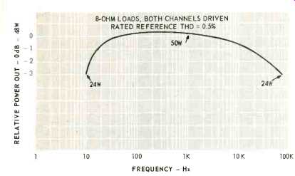
Fig. 9--Power bandwidth.
Listening Tests
Aside from our "FM station logging" tests, most of our listening was done using phonograph records and we can tell you that 37 watts per channel drove our low efficiency systems more than adequately. Even though Pioneer offers connections for three pairs of speaker systems, their switching wisely limits operation to only two out of three systems simultaneously. To do otherwise would tax the amplifier's power capability (we tried it), not to mention the problem of impedance matching. With speaker impedances varying greatly over the audible frequency range, you'll want to make sure that you are at least 8 ohms over the entire audio range if you plan to use two inefficient pairs as we did.
FM reception was all our measurements implied it would be. The center-tune meter was absolutely accurate in indicating proper center-of-channel tuning. This meter's lighting, by the way, is extinguished when you switch to AM, since the meter is of no use in that listening mode. Selectivity was excellent and with a bit of antenna rotating we picked up some 54 usable signals, of which 28 were broadcasting in stereo. With the mute switch engaged, this figure was reduced to 46, which means that we were previously receiving some 8 signals at strengths of less than 6 microvolts and still found them "listenable." Incidentally, we have had some comments about our "logging" numbers and hasten to point out that the absolute numbers from review to review are not always indicative of a set's sensitivity since, at various times of the day when we perform our tests, some of the low-powered educational stations occupying the lower portion of the FM band may or may not be broadcasting and this often affects our total markedly.
We understand that Pioneer has also introduced a higher powered version of this receiver, called the SX-828. Not having seen this "top of the line" receiver, we can't readily say whether the higher power is worth the added expense-but this much we can say: Having put the Pioneer SX-727 through every test we can perform and having listened to it for some twenty hours or more, we find it to be a rugged, reliable instrument that certainly represents state-of-the-art receiver technology in its design and performance.
--Leonard Feldman
(Adapted from : Audio magazine, May 1972)
Also see:
Pioneer Model SX-990 Stereo FM/AM Receiver (Jan. 1970)
Pilot Model 366 Four-Channel Receiver (Mar. 1974)
Pioneer Model SX-1980 Stereo AM/FM Receiver (Equip. Profile, Sept. 1978)
Pioneer SX-V90 Audio/Video Receiver (Jan. 1985)
Fisher RS-Z1 Receiver (Aug. 1990)
= = = =