I suppose few products in the Hi Fi world (with the exception of loudspeakers) are advertised with such exuberance as magnetic tape. Each manufacturer proclaims that his tape is the absolute best with the lowest noise, highest output and widest frequency response. New coating materials and improved formulations are launched almost every month with fanfares of publicity. And so we have Low Noise, Ultra Dynamic, Super Dynamic, High Efficiency, Low-Noise-High Output and dozens of other permutations-no wonder many people are confused and a little skeptical! Tape recording parameters are very much of a compromise with bias, equalization and output adjusted for frequency response, noise and distortion-all conflicting requirements.
For example, a high value of bias might well reduce distortion at mid-frequencies but at the cost of a lower output above 10 kHz or so. Thus a tape with a rising frequency response, a characteristic of the new formulations, will help matters considerably. Figure I shows what happens when a Low Noise tape is played on a recorder matched to a normal tape. It will be seen that the response rises from about 3 kHz.
If the amplifier treble control is turned down to get a more or less flat response, the inherent noise will be reduced too.
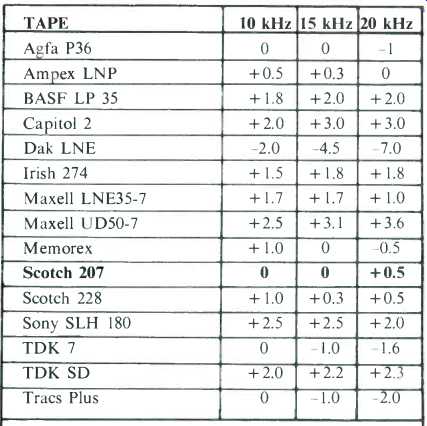
Present day recorders are fitted with a switch--usually labeled Normal and High to cope with these LN tapes by changing the bias and equalization and the net result is a reduction of noise by some 4 dB-plus an extended high frequency response. Machines are matched for one particular tape at the factory and the first objective of our survey was to determine how the tape characteristics varied. These tests were made with a TEAC 1230, a medium priced deck, selected for its high overall performance and because of the accessibility of the bias adjustments. First, it was carefully matched for Scotch 207 tape so the response was within 0.5 dB up to 20 kHz and then the other tapes were checked, without changing the bias. Frequency runs were made from 1 kHz to 20 kHz with a recording level of -20 VU. Levels were adjusted to 0 dB at 1 kHz and the results tabulated for three frequencies, 10 kHz, 15 kHz and 20 kHz as shown in the chart. Variations at 15 kHz ranged from -4.5 dB for the Dak to +3.1 dB for the Maxell UD. In theory, tapes with the highest increase would have the best signal-to-noise potential but this is also dependent on sensitivity and other factors.
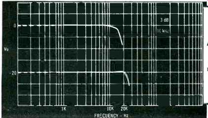
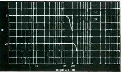
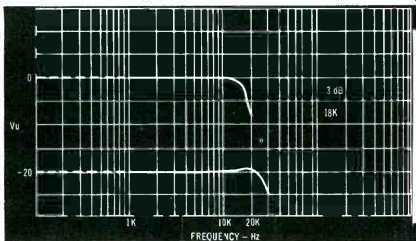
For the next series of tests, the recorder was adjusted to suit each individual tape, using only the bias control and frequency responses taken at the standard input level of -20 VU. Equalization was unchanged and only the bias was adjusted-not too difficult to do with most recorders. Results are shown in the graphs. The response below I kHz is not shown as the low frequency deviations were insignificant.
Then the measurements were repeated at a higher signal level -0 VU, a drastic test which shows the effect of tape saturation or maximum capacity. This has long been a limiting factor on obtaining good transient reproduction and it is also why it is still standard practice to measure recorders at the 20 VU level. Obviously this cannot give a true indication of performance and in the future our tests of recorders will be made at the higher signal level. It will be noticed that all the tapes show some falling off above 15 kHz but even the worst has more `headroom' than the best tapes of a few years ago.
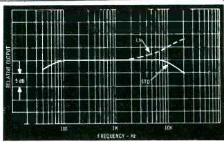
Fig. 1--Showing the frequency response of a typical LN tape played on a recorder
adjusted for normal tape.
Distortion was measured at 0 VU and +3 VU at 1 kHz and signal-to-noise computed. The standard 3% distortion level was used and the ASA weighting employed. It was felt that this method gives a truer indication as the curves are based on human hearing characteristics and it also reduces the effects of low frequency preamplifier noise, (See figure 2). The figures do include some residual electronic noise-note also that a half-track machine would give a further 3 dB improvement. Finally, output at 0 VU input (1 kHz) was measured using 0 dB with the Scotch 207 as a reference.
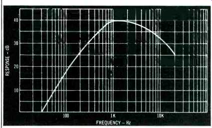
Fig. 2
Dropouts
Dropouts, not the scholastic kind, can be caused by minute imperfections in the tape which push it away from the head. The effects are more audible at high frequencies and tape speed plays a part too. A dropout might pass unnoticed at 7 1/2 ips but sound horrendous at 1 7/8 ips. And so they are more noticeable on cassette machines where mechanical difficulties compound the problem.
The usual method of assessing dropouts is to record a high-frequency signal on the tape for 3 to 15 minutes, then playing back and watching the variations on an output meter.
This is tedious and seems a little crude and so work is proceeding on an automatic counter detector (we are just lazy, that's all). In the meantime, the 15 tapes were checked using the first method and all were found satisfactory.
As far as open reel is concerned, we had long thought the dropout problem (when it was not due to pressure pads) was due to bad handling and some tests made by the Boston Audio Society seem to confirm this opinion. These tests were made by Alvin Foster who writes in the BAS publication.
"Dropout is particularly severe in the first and last feet of most open reel tapes due mainly to the mistreatment that these sections endure in the normal loading and unloading of the tape. This is the reason why some manufacturers include a few feet of leader tape and why tape recording perfectionists never record a signal on the first or last few feet of tape.... I was surprised to find such noticeable deterioration between new and slightly used tapes and was convinced that careful handling of tape is a prerequisite to good recording. Even the type of reel one used affected dropout.
Take up reels which cover the tape with only one or two small holes for threading protect it because the larger plastic area covering the tape inhibits pinching or creasing of tape as the reel is handled. The pressures exerted when handling the reel of tape are distributed more evenly over the tape edges." We would add that the back coatings used by Scotch and Capitol are definitely a step in the right direction as they not only tend to improve traction but strengthen the tape as well.
What do the tests show? In brief, they confirm that the new generation of tapes, Low-Noise, Super-Dynamic or whatever, do give a worthwhile improvement; moreover, signal-to-noise is so good that you can record at a lower level and avoid the risk of peak overloading. But the divergences mean that the recorder must be adjusted to suit. That is, if you want the best results-and who doesn't.
Next month, we compare cassette tapes.
==============
Table 1--Frequency responses compared with Scotch 207
===========
Agfa PE 36 I mil polyester, plastic case, leader tape. Output +1 dB, signal/
noise 67 dB. Distortion 0 VU 1.1%, +3 VU 2.5%.
Ampex LNP 1 mil polyester, plastic case, no leader tape. Output 0 dB, signal/noise
67 dB. Distortion 0 VU 0.95%, +3 VU 2.8%. Frequency response nearly identical
to Scotch 207.
BASF LP 35 1 mil polyester, plastic case, leader tape. Output +0.5 dB,
signal/noise 69.5 dB. Distortion 0 VU 0.6%, +3 VU 1.1%. Low distortion with
good headroom.
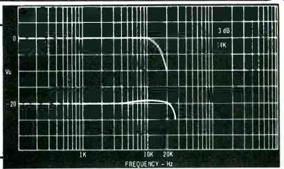
Capitol 2 1.5 mil polyester, plastic case, no leader tape. Output 0 dB,
signal/noise 68 dB. Distortion 0 VU 0.75%, +3 VU 2.0%. "Cushion-aire" back
coating.
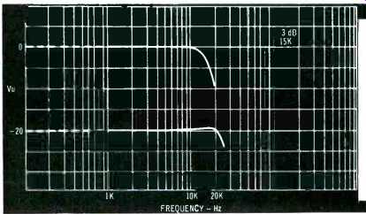
Dak Low Noise 1 mil polyester, cardboard box, no leader tape. Output +
0.5 dB, signal/noise 62 dB. Distortion 0 VU 1.2%, 0 VU 3.2%. An inexpensive
tape with excellent frequency response, good headroom but with slightly
inferior signal/noise.
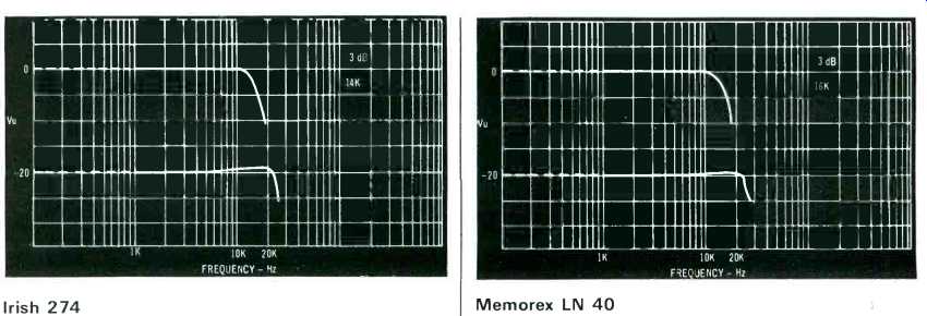
Irish 274 1 mil polyester, cardboard box, leader tape. Output-2 dB, signal/noise
68 dB. Distortion 0 VU 0.6%, +3 VU 2.1%. Memorex LN
40 1 mil polyester,
plastic case, leader tape. Output-0.5 dB, signal/noise 67 dB. Distortion
0 VU 0.7%, +3 VU 2.8%. Rear coating. Bias requirements similar to Scotch
207.

Maxell LNE 35-7 1 mil polyester, leader tape. Output 0
dB, signal/noise 70.5 dB. Distortion 0 VU 0.65%, +3 VU 1.6%. Excellent
signal/noise and good headroom. Scotch 207 1 mil polyester.
Scotch 206 is similar but is 1.5 mil polyester. Output 0 dB signal/noise
68.5 dB. Distortion 0 VU 0.6%, +3 VU 1.6%. Rear coating.
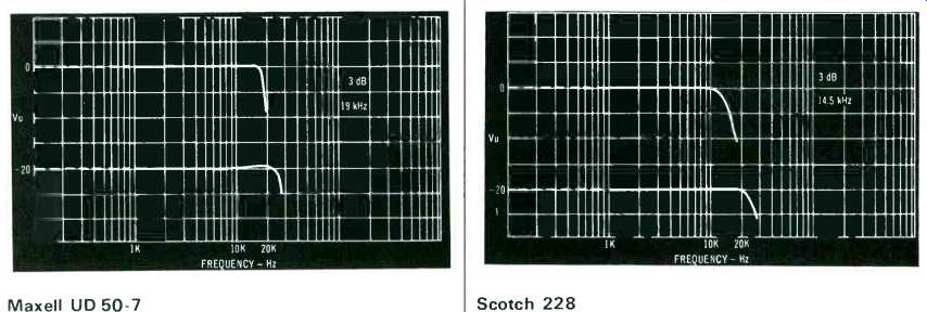
Maxell UD 50-7 1.5 mil polyester, cardboard box, leader
tape. Output-0.5 dB, signal/noise 70.5 dB. Distortion 0 VU 0.7%, +3 VU
1.5%. Similar to LNE with greater headroom-one of the best. Scotch
228 1.5
mil polyester. Scotch 229 is similar but is 1 mil polyester. Cardboard
box, leader tape. Output-1 dB, signal/noise 68 dB. Distortion 0 VU 0.9%,
+3 VU 2.8%. One of the Highlander series-probably a best buy for those who
like Scotch tapes but prefer to save money and do without the fancy plastic
box!

Sony SLH 180 1 mil polyester. Cardboard box, leader tape.
Output -1 dB, signal/noise 69 dB. Distortion 0 VU 0.7%, +3 VU 1.9%. TDK
SD 1 mil polyester. Plastic case, leader tape. Output +2 dB, signal/ noise
70 dB. Distortion 0 VU 0.6%, +3 VU 1.6%. Similar to TDK 7, but greater headroom.

TDK 7 1 mil polyester. Plastic case, leader tape. Output +2 dB, signal/noise
70 dB. Distortion 0 VU 0.7%, +3 VU 1.6%. One of the highest outputs in
the group tested. Tracs Plus 1.5 mil polyester. Plastic case, leader
tape. Output 0 dB, signal/ noise 68.5 dB. Distortion 0 VU 0.7%, +3 VU 1.8%.
A new tape from Audio Magnetics.
==============
Simple Volume Compressor
by Daniel Shanefield
Present Address: Western Electric Co., Princeton, NJ. 08540
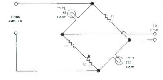
Fig. 1--Volume compressor, for fractional-wattage speaker dissipation.
The type 48 lamp is a 2 volt pilot light, which is a 33 ohm, hot-filament
resistor at its rated 60 ma but is about 12 ohms when cold. The type 222
is a two cell penlight bulb, which is rated 250 ma and is 9 ohms hot and
3 ohms cold.
With medium-quality music reproducing systems, the details of very quiet recorded passages can only be heard by turning the gain control to a high value.
However, louder passages will inevitably follow, also at the high gain. The listener's family or neighbors are often not so vitally interested in the music as to enjoy the ensuing blasts. (The listener himself may not enjoy the ensuing counterblasts from the other people!) To promote harmony of the interpersonal kind, a compressor is useful for limiting the louder passages to a maximum volume, while allowing the desired high gain for the softer passages.
A volume compressor can be obtained as a built-in part of at least one commercial amplifier [1], or it can be constructed at home according to the various plans described in previous articles [2,3,4]. These are sophisticated and complex circuits.
A very simple compressor is illustrated in Fig. 1. It does not perform as well as the more complicated circuits (for instance, it is not as fast), but most listeners will find it to be adequate. At the correct setting of the variable resistor, this circuit limits volume peaks without being an intrusive presence.
The main circuit element is a pilot lamp which acts as a nonlinear resistor.
The effect is multiplied by making a differential comparison to a fixed resistance, using a Wheatstone bridge design.
The types of lamps should be chosen according to whether the speaker is efficient or inefficient. The values in Fig. 1 are for cases where less than 1 watt is dissipated in the speaker. This is as much as most people actually use with efficient systems. Less efficient speakers can be handled by a pair of type 222 bulbs instead of the combination shown. For people who can listen to several watts of actually-dissipated output, type 13 bulbs for three-cell flashlights can be used, instead.
One of the circuits shown is required for each stereo channel.
References
1. Bogen Model BR 360 Receiver, as listed in Audio, Sept. 1971, p. 34.
2. R. R. Russell, “Build a Hi-Fi Volume Compressor/Expander," Popular Electronics, Oct. 1964, p. 41.
3. J. C. Wright, "Audio-Compression Preamplifier," Electronics World Nov 1964, p. 32.
4. S. S. Andrews, "Low-Cost High-Performance Volume Compressor," Audio, Dec. 1964, p. 19.
(5) C. Caringella, "Distortionless Audio Compressor," Popular Electronics, December 1971, p. 25.
================
(Audio magazine, May 1973)
Also see:
A Primer on Choosing Audio Tape (Sept. 1974)
Cassette Deck Transport Problems (Sept. 1974)
= = = =