MANUFACTURER'S SPECIFICATIONS:
FM TUNER SECTION:
IHF Sensitivity: 2.0 V. S/N Ratio: 70 dB.
THD: Mono, 0.4%; Stereo, 0.5%.
Capture Ratio: 1.6 dB. Selectivity: 60 dB.
AM Suppression: 60 dB.
Image Rejection: 90 dB. IF Rejection: 90 dB.
Spurious Response Rejection: 90 dB.
Stereo FM Separation (1 kHz): 37 dB.
AM TUNER SECTION:
IHF Sensitivity: 300 microvolts/meter (internal antenna).
Selectivity: Better than 35 dB.
IF Rejection: Better than 60 dB.
Image Rejection: Better than 60 dB.
AMPLIFIER SECTION:
Power Output: 4 x 32 watts continuous, into 8 ohm loads, at any frequency from 20 Hz to 20 kHz, all channels driven; in two-channel mode, 90 x 2 watts continuous power, 8-ohm loads, 20 Hz to 20 kHz, both channels driven.
THD: Less than 0.5 percent at rated output.
IM: Less than 0.15 percent at rated output.
Power Bandwidth: 10 Hz to beyond 40 kHz.
Hum and Noise: Better than -75 dB (unweighted).
Damping Factor: 30 at 8 ohms.
Frequency Response: 4 Hz to beyond 70 kHz, ± 0.5 dB; from 1 Hz to beyond 100 kHz + 1 dB.
Phono Sensitivity: Variable, depending upon separation of CD-4 adjustment.
Bass Control Range: + 12 dB at 50 Hz.
Mid-Range Control: + 12 dB at 1 kHz.
Treble Control Range: + 12 dB at 10 kHz.
GENERAL SPECIFICATIONS:
Dimensions: 20 1/8 in. W x 17 in. D x 6 1/4 in. H.
Weight: 45 pounds.
Price: $749.95, including walnut enclosure.

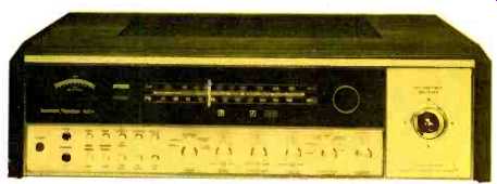
Harman/Kardon was one of the first high fidelity component manufacturers to introduce 4-channel receivers that provided higher-powered stereo operation at the option of the user by permitting back and front amplifier pairs to be "strapped" or paralleled together until such time as the owner elects to purchase that second pair of loudspeaker systems and go "all the way" to quadraphonic sound. The success of the format is evidenced by the growing number of manufacturers who have followed this lead since H/K's introduction of the concept with their earlier 75+, 100+ and 150+ receivers more than a year and a half ago. Now, H/K has come up with more powerful (and much more flexible) receivers that combine the multi-channel 2/4 concept with a host of other features worth talking about--and listening to. The Model 900+, the most powerful of the three new receivers in the line, carries over into it many of the design innovations of that company's famous Citation components. For example, the left portion of the blacked-out dial area features a very large meter which operates differently from the usual signal-strength meter. Its pointer reads all the way up-scale until you tune to an FM station, at which point the needle deflects down scale and indicates noise quieting rather than just signal strength. Numerical calibration of the meter is opposite to that of conventional signal-strength meters and, while this might seem to be a minor point, we found the meter circuit to be far more useful in tuning for best signal than the other kind. As a further aid towards best, lowest-distortion tuning, the lighted words "IN TUNE" appear next to the meter when a station is correctly tuned. AM and FM dial scales are well spread out and a logging scale is also provided. Numerals below the dial scale light up to denote mode of operation, such as "1," "2," " 4-2-4," "2-4," and "4-4" for mono, stereo, matrix, stereo enhance and discrete four-channel positions of the mode switch.
The lower section of the control panel contains an illuminated power on/off switch, a pair of phone jacks (for front and rear channels), the mode switch, bass, treble and midrange tone controls (each of which is a dual concentric type for separate control of front and rear channel tonal settings), a program selector switch and the master volume control. Just to the right of the headphone jacks are a series of ten push buttons. Four of these individually control front and back main and remote pairs of speakers, while the remaining six control the two tape monitoring circuits, FM muting on-off, loudness on-off, and high and low filter on-off. The rightmost section of the front panel is entirely devoted to a joy-stick four-channel balance control, which H/K calls a sound-field balance control.
We have reported on this multi-function control before, and again find that it is the easiest type of control with which to balance all four channels simply. This version of the joystick has very positive positions (at 45-degree angles to either the vertical or horizontal) which permit listening to a single speaker at a time with no audible sound coming from the other three--a feature we found particularly useful in adjusting the CD-4 calibration controls for proper operation with our test phono cartridge.
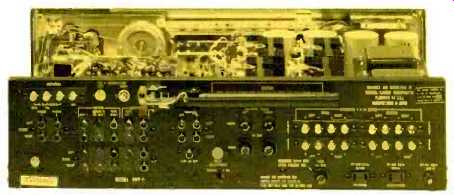
Fig. 1--Rear panel layout.
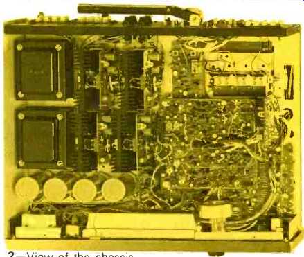
Fig. 2--View of the chassis.
These separation calibration controls, along with a muting threshold adjustment, are found on the rear panel, shown in Fig. 1. The rear panel also contains all the usual input and output jacks as well as a four-channel FM output jack for use with a future decoder when FM discrete four-channel broadcasting begins. There are two pairs of phono inputs, either one of which may be used for stereo or CD-4 cartridges. In addition to the two tape monitor groups, there are jacks specifically labeled for use with a Dolby external accessory box, which are part of the Tape Monitor 2 circuitry. Four speaker fuses and a line fuse are also replaceable from the rear panel. Antenna input terminals for both 300-ohm and 75-ohm connection are provided, as are front and back speaker terminal strips for main and remote quartets of speakers. A stereo/4-channel slide switch located below the FM mute adjust control has a protective metal strip retaining it in the tour-channel position to prevent accidental switching. A pair of a.c. outlets (one switched, the other unswitched) and a pivotable AM ferrite bar antenna complete the rear panel layout.
We are unable to obtain a full schematic diagram of the H/K 900+, nor is one supplied with the owner's manual, so that a detailed description of the circuitry used cannot be given here.
A look inside the chassis (Fig. 2) helps to explain how Harman/Kardon was able to build this much receiver into so small a cubic volume. Circuit board modules are actually "layered" inside the unit, which might make servicing a bit more difficult if it is ever required. However, all circuits are arranged in an orderly fashion and, visually at least, we could see no problems insofar as rigidity of mounting or potential heat problems are concerned. Neither the CD-4 demodulator circuitry nor the SQ decoder uses IC chips for complete decoding, although we saw a sprinkling of stock IC's in these and other circuit modules.
Laboratory Measurements
The FM tuner portion of the receiver was measured in our laboratory and was found to have an IHF sensitivity of 2.4 µV-a bit short of the 1.8 µV claimed. Quieting of 50 dB (in mono) was achieved with a signal input of only 3.8 microvolts-a very acceptable figure for this amount of S/N quieting. (See Fig. 3). Ultimate S/N measured 68 dB as against 70 dB claimed, but mid-frequency THD exceeded claims in mono mode, with a reading of 0.25 percent. In stereo mode, the reading was a bit higher than claimed, at 0.6 percent. We found, however, that if the unit was re-tuned in stereo, this figure decreased to 0.3 percent. However, the minimum distortion point in stereo tuning did not correspond with the separation point, as we learned when making separation measurements, later on.
In terms of actual use, whenever we run into a situation of this kind, we favor the "low distortion" tuning point, since separation is usually more than adequate on modern stereo receivers even if it is not "meter optimized." Stereo S/N was only about 55 dB, but the residual content was not really "noise," as such, but rather residual subcarrier product outputs. If this output is ignored, actual S/N exceeds 60 dB in the stereo mode. Since we were concerned with this rather high level of 38-kHz residual output, we made some single tone recordings from FM, using a cassette deck (which usually has a lower bias frequency than do open-reel machines) and encountered no audible "beats" in the recorded results, despite the relatively high" level of sub-carrier output.
Figure 4 reveals that stereo FM separation was better than 30 dB from 50 Hz all the way up to 10 kHz, reaching its maximum of 42 dB at mid frequencies. THD in mono remains under 0.5 percent for all audio frequencies used in FM and under 1.0 percent for stereo under the same conditions. In making this measurement, the tuner was re-tuned slightly to achieve lowest distortion readings, as previously noted. Other measurements made on the tuner section and not shown in the graphs included capture ratio, at 1.5 dB, selectivity, which measured just over the 60 dB claimed, and AM rejection which was 60 dB, exactly as claimed. I.f., image and spurious rejection were at least -90 dB, and possibly higher, measurements being limited by our equipment.
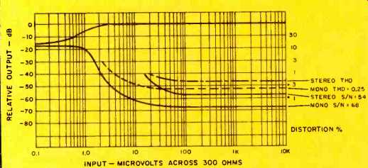
Fig. 3--FM quieting and distortion characteristics.
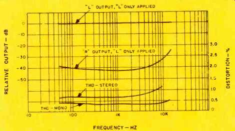
Fig. 4--Separation and distortion vs. frequency.
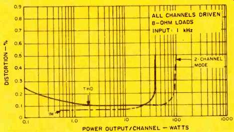
Fig. 5--Harmonic and intermodulation distortion characteristics.
Amplifier Section
If tuner performance was a bit marginal (compared to published specs), amplifier capability of the H/K 900+ exceeded claims in almost every respect. Less conservative manufacturers would surely have rated the power output of this unit at 40 watts per channel, in 4-channel mode, for that is exactly what we measured with a THD of 0.5 percent and a frequency input of 1 kHz. At lower power levels, THD measured a consistent 0.1 percent, except at very low power levels when it tended to increase slightly, as shown in Fig. 5. IM distortion, also plotted in Fig. 5, was about 0.08 percent at listening levels below rated output, rising almost exactly like the THD curve to reach 0.5 percent at an output of 40 watts per channel. Power bandwidth, plotted in Fig. 6, extends from 10 Hz to 60 kHz-a good deal broader than claimed. Harman/Kardon has always believed in wide band amplifier response and the 900+ certainly follows that design philosophy. As shown in Fig. 7, rated output (32 watts per channel) is attainable from 20 kHz down to 30 Hz at less than 0.5 percent. At 20 Hz, it is 0.6 percent-certainly close enough to H/K's claims. Although all measurements were not repeated for the higher-powered "strapped" 2-channel mode, we did check for rated THD of 0.5 percent and found that each channel produced 100 full watts (against 90 claimed) before this value of THD was reached. At half power levels (also shown in Fig. 7), THD remained close to or under 0.1 percent for all audio frequencies.
While we have previously tested other receivers and amplifiers equipped with separate bass, mid-range, and treble controls, the H/K mid-range control operates over a narrower frequency range than most, as can be seen in Fig. 8. As such, it provides a very immediate and noticeable effect on voice recordings and does not overlap the action of the bass and treble controls, also shown in Fig. 8. More about this feature when we discuss use and listening tests. Both high and low frequency filters have a slope of only 6 dB per octave and follow bass and treble cut curves almost exactly, making them not significantly more effective than these continuously variable controls. Loudness contour action, measured at-30 dB from full volume setting, conforms nicely with theoretical requirements. Hum and noise level of high level inputs, referenced to full output, was 84 dB, while phono hum and noise was 62 dB below full output.
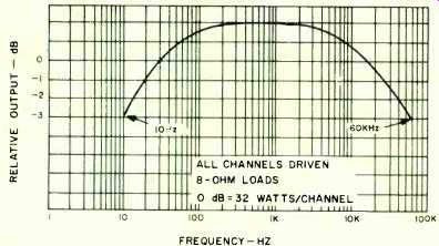
Fig. 6--Power bandwidth characteristics.
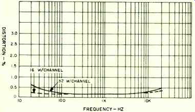
Fig. 7--Distortion vs. frequency.
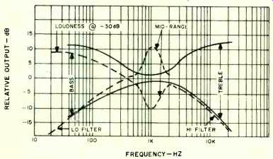
Fig. 8--Tone control range, filter and loudness characteristics.
Use and Listening Tests
It was only when we tried to use the tuner section of the H/K 900+ to receive a variety of stereo stations that we realized that there was another adjustment we had missed. It is not mentioned in the owner's manual and has to do with the stereo threshold settings. This additional adjustment is located under the chassis where you are unlikely to find it unless you know it's there. In any case, we were able to adjust the stereo threshold to a low setting of 15 µV (before our adjustment, it took over 25 µV of input signal strength to cause the circuits to "switch" into stereo-too high a figure in view of the good quieting characteristics of the tuner section). The muting range of adjustment is from 4.5 µV to 90 µV--a more reasonable pair of end points. Of the two tuning indicators present (the quieting meter and the "in tune" light), by far the most useful one is the quieting meter. It performs much better than a signal strength meter and really does show the "quietest" (and therefore best) tuning point when used in accordance with instructions. The "in-tune" light, we feel, is more of a psychological "security blanket" than anything else, in that its "window" or the number of kHz over which it remains lit, is a little high.
Fortunately, the if. and detection system of the tuner is so good that even if one tunes to the "edge" of the range over which the light stays on, distortion measures less than 1.0 percent. Incidentally, we consulted some of the engineers at H/K and, after getting a brief description of how the quieting meter works, we can confirm that it is NOT just a signal-strength meter "hooked up to read backwards"--as one might at first suppose. We feel, therefore, that it is a significant contribution to good FM tuner design and use and hope that it will find Its way into many more FM products.
In general, FM reception was clean, free of audible interferences, and as sensitive as we would expect from the measurements made on the bench. Dial calibration was a bit off at the high end (about-300 kHz at 108 MHz). The discrepancy between "best separation" tuning and "lowest distortion" tuning was really not observable in actual practical use of the receiver.
Four-Channel Use Tests
The 12-in. LP test record which H/K gives away with each receiver is a very good way to introduce the user to CD-4 records. In addition to containing a well-narrated calibration band (far better than the one contained in the older 7-in., 45 rpm disc made by JVC and distributed with most competitive receivers), the record contains a variety of well-recorded selections designed to demonstrate the virtues of CD-4 discrete discs.
It succeeds in this respect, and so does the demodulator circuitry of the 900+, which afforded well over 20 dB of separation in every direction between all channels. Separation nulls achieved by varying the two separation adjustment controls on the rear panel were very positive and easily set even "by ear" (the way most users will have to set them). Several other CD-4 discs were auditioned on the H/K 900+, and all performed well, with noticeably lower distortion than we have heard on earlier demodulator circuitry.
As far as the "matrix" positions and the playing of matrix discs is concerned, the circuitry contained in the 900+ includes no logic and is therefore a bit limited in terms of front-back separation capabilities. In this respect it is no different from most other SQ circuits contained in the current crop of "all-in one" four-channel receivers.
Harman/Kardon describes one very interesting mode of operation in their owner's manual which we could not resist trying. By connecting a pair of audio jumper cables from the tape monitor jacks to the tape out jacks (front channels only) and a stereo tape recorder to the back channel tape monitor receptacles, it is possible to use the 900+ as a "double stereo system." That is, when the tape monitor switch is activated, you can listen to any program source selected from the front panel reproduced over the front speakers, while the back speakers can be used to listen to the tape recorder. Obviously, this comes off a lot better if the pairs of speakers are in different rooms (or, if the front main speakers are used for one stereo program, and the back remote speakers are used for the other--which amounts to the same thing). A nice feature, and probably one of the reasons H/K refers to these receivers as "multi-channel," rather than just 2/4 channel.
Audio performance is excellent, transparent and powerful enough for our low efficiency speaker systems. We found that anything above moderate use of the mid-range tone control (on the "boost" side) leads to a rather high amount of "presence," but when used in moderation, the control is a welcome addition to the front panel. Action of the sound-field balance joystick is smooth and despite the limited physical travel of the stick in any direction we had no trouble balancing all channels or favoring any one of them to the precise degree desired. A wonderful control, as we've said before! With such an excellent panel layout, compact size (for its power capability), and performance, plus the "bonus" CD-4 record, we wish H/K would devote a little more effort to their instruction manual. Besides overlooking reference to that "hidden" stereo threshold control, the book offers no data about the circuitry of the receiver, nor does it give performance specifications (we had to obtain these from a separate brochure supplied, after request, by H/K). We realize that not every owner is "technically-oriented" and we are all in favor of "broadening the base" of high fidelity component acceptance, but since the reader is at liberty to "skip" those sections that seem too technical, we don't see any harm in including as much information as possible for the interested user.
At $750.00, the Harman/Kardon 900+ ranks right up there with the few "better" quadraphonic receivers available on the market this year.
--by Leonard Feldman
(Audio magazine, May 1974)
Also see:
Harman-Kardon Model 930 AM/FM Stereo Receiver (Jun. 1972)
Harman/Kardon Rabco ST-7 Turntable (Jan. 1977)
= = = =