By Martin Clifford
LANGUAGE, basically intended to improve communications, sometimes behaves perversely and, seemingly deliberately, compounds confusion. The word components is an example. In high fidelity it refers to the parts of a system-the tuner, amplifier, record player, tape deck, and speaker system. But it also means the individual parts that comprise these components--parts such as resistors, capacitors, coils, conductors, tubes, and solid-state devices.
These electronic parts or components, although different in appearance and behavior, all have a common function--to take a signal voltage, guide it, strengthen it, and to let it emerge unscathed to the final transducer-the speaker system. Unfortunately, the word voltage is a simplification and gives us no inkling of the large variety that exists.
Voltages are easy to produce; so easy in fact, it's almost impossible to avoid doing so. Walk across a rug, rub your lapel, drive your car--in each instance you produce a voltage, sometimes more elegantly known as an electromotive force and promptly made less elegant by abbreviating it as EMF. These voltages are not always controllable--often just a nuisance, but sometimes are dangerous. Controlling a voltage is easy if it is man-made rather than naturally produced. One of the earliest man-made techniques (now about 200 years old) for producing a controlled voltage is to use a chemical technique--a battery.
Electrons
The word volt is a name identifying a physical condition, but does not describe it. Voltage is predicated on the behavior of extremely tiny particles called electrons. Electrons are associated with atoms and form part of their structure, and because of this may be termed bound electrons. Electrons, though, may also be independent or free. Their unique feature, whether atom associated or not, is that they all carry a negative electric charge. Get enough of them together on some surface and you will have developed an electrical pressure, or force, between the electron crowded plate and a nearby plate relatively free of electrons. This electrical pressure, created by the fact that each electron demands its lebensraum and repels other electrons, is voltage.
Voltage, or electrical pressure, or electron pressure, or EMF, is due to a difference in electron quantity on two surfaces, often adjacent. However, when electrons do move, they are referred to as a current. And so voltage and current are inextricably bound. It is possible to have voltage without current flow just as it is possible to have physical pressure without movement, hence the use of separate labels, voltage and current, makes electronic sense.
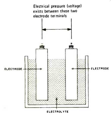
Fig. 1--Electrons taken from the electrode at the right make it positive.
The electrons move through the electrolyte […] the electrode at the left, making
it 4g EMF now exists between […].
The Battery
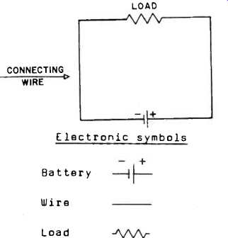
Fig. 2--A load is any device drawing current from a voltage source, such as
a battery.
A battery is a chemical method for removing electrons from one substance and then transferring and storing them on another. Two identical metal plates adjacent to each other in a glass of water do not supply a voltage since the number of electrons on each plate may be about the same. Change the plates so they are of different metallic substances, immerse them in an alkaline or acidic liquid and you have a voltage producing device. The liquid (Fig. 1) called an electrolyte, robs one of the plates of electrons and transfers them to the other plate. Since electrons have a negative charge, the electron-enriched plate or electrode becomes negative (or minus). The other plate, deprived of many of its electrons is less negative than formerly, or, saying the same thing, is positive (or plus). An electrical pressure or EMF now exists between the two plates. There is an electron migration inside the battery from one plate to the other and because there is no longer an electron balance there is a voltage between the exposed terminals connected to the electrodes.
Connect a wire (Fig. 2) from one terminal to the other and there will be a flow of current through it, external to the battery. It is this external current we want to use and control.
Cells and Batteries
Technically, this voltage producing chemical factory isn't a battery, but a cell with two or more connected units does form a battery. The current obtainable from a cell is a function of its physical construction. The larger the electrode plate area, the greater the current capability. A 12-volt car battery is much larger and heavier than eight 1 1/2-volt transistor batteries. The big difference is one of current capability, not voltage.
More Voltage, More Current, Or Both
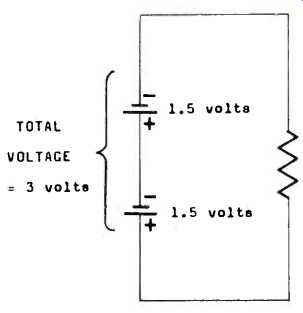
Fig. 3--When cells are connected in series the total voltage is the sum of
the individual cell voltages.
To get more voltage we connect cells in series (Fig. 3), an arrangement in which the plus terminal of one cell is wired to the negative terminal of the next, analogous perhaps to circus elephants proceeding in single file, trunk to tail. To get more current (Fig.4), we wire cells in parallel (or shunt) with all plus terminals connected, and all minus terminals connected. To get more voltage and current (Fig. 5), we combine series and parallel wiring methods.
Current Flow Opposition
The movement of current, whether through a liquid or solid, isn't smooth or free, but encounters a certain amount of opposition generally known as resistance. Any substance that permits the relatively easy passage of electrons through it is called a conductor, but the amount of opposition or resistance to electron passage varies, depending on the material of which the substance is made, its volume, and the temperature. Copper is a commonly used conductor. So is aluminum. Silver is a much better conductor (it has less resistance) but is much more expensive.
However, we are not only interested in forcing a current to flow through a wire but to get it to do some useful work in the process. Thus, the external current flow of a battery can be made to do this by inserting some component, such as a light bulb, in the wire connecting the battery terminals. (Fig. 6)
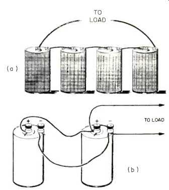
Fig. 4-Cells can be wired in series (a) to supply more voltage, or in parallel
(b) to supply more current.
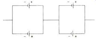
Fig. 5--Circuit diagram of a parallel arrangement of cells.
Current Control
To permit current to move with minimum opposition from one point to another, we connect them with copper wire. This permits maximum flow, but it is often in our interest to regulate the amount of current, to permit only precise amounts to flow between parts. Resistors are simple devices for letting us do so. Made of carbon compressed with a special binder or a. special kind of wire alloy (such as the wires used inside your toaster), they can govern current quantity quite effectively. The larger the amount of resistance, the smaller the flow of current. A substance that allows very little or no current flow at all is called an insulator. Resistors are used to govern amount of current flow; insulators for keeping currents in their proper paths.
The basic unit of resistance is the ohm, often represented by the Greek letter omega, Ω. Multiples of the ohm are the kilohm, abbreviated as KΩ, or thousand ohms, and the megohm, often abbreviated to meg.
Some resistors, particularly those designed for use in test instruments, are manufactured with considerable precision. Inexpensive, mass-made receivers may use resistors having wide tolerances.
Precision costs money but precision is often needed for very fine current control.
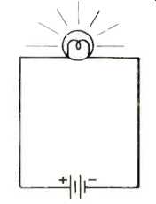
Fig. 6--In this diagram the current is utilized to light a lamp.
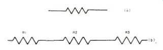
Fig. 7--Symbol for a resistor (a) and resistors in series (b). When resistors
are series connected, the total resistance is equal to the sum of the values
of the individual resistors.
Resistor Combinations
Although the resistor is a current controlling component, further refinement in current control is obtainable by connecting resistors in various combinations. One technique is to wire resistors so that the total opposition to current flow is increased. Known as a series circuit, just as in the case of series-wired cells, the resistors are connected so that the same current flows through each. Thus, a 100-ohm resistor in series with another 100-ohm resistor, behaves like a single 200-ohm unit. Resistors can be wired in series to obtain values not normally obtainable. The total resistance is then equal to the sum of the value of the individual resistors.
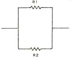
Fig. 8--Resistors in parallel.
Another current controlling technique using resistors is to wire them in parallel or shunt (Fig. 8), a method that reduces the overall resistance. When two resistors are in parallel, the current has two paths, hence the opposition to flow is lowered. To find the equivalent resistance of two resistors in parallel involves arithmetic, but nothing more than ordinary multiplication and division. Multiply the values of the two resistors and then divide by their sum. If you have a 6-ohm resistor in parallel with a 3-ohm unit, 6 x 3= 18.
The sum of 6 and 3 = 9. 18 divided by 9 = 2. Thus, a 6-ohm resistor in parallel with a 3-ohm resistor behaves like a 2-ohm component.
Of course more than two resistors can be connected in parallel and since more current paths are supplied, the overall resistance is reduced further*.
Codes and Values
Resistors in a circuit are often identified by the letter R followed by a number. R1, known as a code, refers to resistor No. 1. R18 is resistor No. 18.
The code identifies the resistor, but tells you nothing more-nothing of the value of the resistor, its size, shape, or purpose.
Adjacent to the resistor in a circuit diagram you will often find the value.
This may be given as a simple number, such as 1,000, or the number may be followed by the omega symbol for resistance. The value supplied in the diagram is the median value--that is, it does not take into account that the resistor has a certain tolerance. A 100 ohm resistor with a tolerance of 10% may have a value ranging from 100 ohms + 10% to 100 ohms 10%. On the diagram, though, the resistor will be identified as 100 ohms, but its true value may be anywhere from 90 ohms (100 ohms 10%) to 110 ohms (100 ohms + 10%).
Voltage, Current and Resistance
Voltage is often represented by the letter E, current by the letter I, and resistance by R. These three are inextricably involved, for we start with an electrical pressure, E, produce a current I, which flows through a conductor or resistor having a certain amount of resistance, R. The relationships of E, I, and R are simple and direct and are best represented by a simple formula known as Ohm's law: E = I X R. This formula (Fig. 9), probably the most widely used in electronics, is less formidable than it looks.
It simply states that if you know the amount of current (in amperes) and multiply it by the amount of resistance (in ohms) your answer will be the voltage (in volts). The formula can be rearranged to read: I = E/R. Divide the amount of voltage by the amount of resistance, and the answer will be the amount of current. And in its third form, Ohm's law looks like this: R = E/I. Divide the voltage by the current value to obtain the amount of resistance.
Fixed vs Variable Resistors
The technique for current control by wiring resistors in series, in parallel, or possibly series-parallel combinations, is useful but it has limitations. Sometimes the amount of current flow needs to be varied smoothly and continuously over fairly wide ranges. This can be done by means of a variable resistor (Fig. 10), known formally as a potentiometer and less formally as a pot.
Every hi-fi system has a number of these components controlled by knobs from the front panel or as a screwdriver adjust type on the rear apron of a component such as an amplifier or speaker system. The pot consists of a resistive element on which a sliding element makes contact.
Power
There are a number of types of energy: chemical, heat, light, electrical. Power is the fate at which energy is produced or used. The basic unit of electrical power is the watt, with submultiples such as the milliwatt (thousandth of a watt) and the microwatt (millionth of a watt). Going in the other direction, a kilowatt is a thousand watts, and a megawatt is a million.
There are various ways of calculating power, one of the more commonly used being the product of voltage and current. Multiply the current (in amperes) by the voltage (in volts) to obtain the amount of power (in watts).
Some electronic parts, notably resistors, both fixed and variable, are rated in terms of watts, a measure of their power handling ability. Resistors range from as little as 1/8th watt to units having values of 100 watts or more. The wattage of a resistor is an indication of its ability to dissipate heat, a consequence of the friction of electron movement through the resistor. The wattage rating of a resistor is an economic factor: the higher the wattage rating, the greater the cost. Wattage ratings are also applied to components, such as audio power amplifiers, but in this instance the rating indicates the sound power output capability of the amplifier.
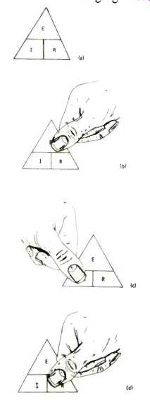
Fig. 9--Ohm's law. The triangles are a memory aid for remembering the various
forms of the law. Ohm's law triangle (a). Drawing (b) shows how to determine
voltage. Cover E with a finger and the answer is I x R. In (c)
I = E/R and in (d) R = E/I.
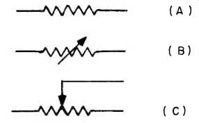
Fig. 10--Resistors can be fixed or variable. Symbol for a fixed resistor (a).
Two symbols can be used for variable resistors, as in (b) or (c).
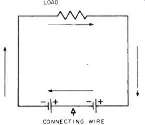
Fig. 11--Arrows are often used to indicate direction of current flow.
* The formula for more than two resistors in parallel is: 1+Re = 1+R1 + 1+R2 + 1+R3 .. .
Let R1 = 3 ohms, R2 = 6 Ohms, and R3 = 2
.... then 1+Re = (1+3) + (1+6) + (1+2)
1/6+3/6= 1 ohm.
Meaning of D.C.
The movement of current external to a battery is uncomplicated. Current always flows from the negative terminal of the battery, through a device (Fig. 11) such as a lamp or a resistor, and then back to the positive terminal. Inside the battery the current moves from the positive to the negative terminal, but normally our concern is with the external movement only.
Current movement is unidirectional no matter what arrangement of resistors or other components are wired to the battery. Because of this steadfastness of direction, the current is called direct, promptly abbreviated as d.c., and leading to such anomalous phrasing as d.c. current which could be translated as direct-current current. The voltage that produces a direct current is a direct voltage, also abbreviated as d.c. and translatable as direct current voltage.
Because of this moderate confusion in terminology, d.c. is often specified as d.c. current or d.c. voltage. Some of the currents that flow through high-fidelity components (tuners, receivers, etc.) are direct. Others, however, more or less periodically, reverse their direction of movement.
Alternating Voltages and Currents
It is possible to reverse the direction of current flow from a battery by transposing its connecting leads. The external battery current still flows from negative to positive or minus to plus, but now the current direction through the resistor is reversed.
An easier method of producing current reversal is through the use of a generator, a large sized version of which delivers voltage and current to the outlets in your home. The basic idea of the generation of a voltage by mechanical rather than chemical means (as in a battery) is an extremely simple one. A magnet (Fig. 12) is plunged into a coil and then removed, with the process being repeated regularly.
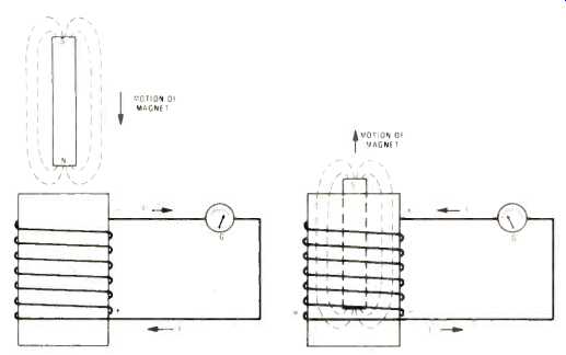
Fig. 12--Electromechanical method of generating a voltage. The voltage produced
is a.c. The small circle with the letter G indicates a galvanometer, a sensitive
current measuring instrument.
The moving magnetic field of the magnet as it goes into the open form around which the coil is wound causes some of the electrons inside the coil wire to collect at one end of the wire, leaving the other end with a deficit. However, an electron displacement, just as in the case of a battery, means the production or generation of a voltage. In the case of the coil, the end with the electron surplus is negative; the other end is positive.
However, when the freely moving magnet is pulled out of the coil, the situation is reversed. The electrons rush from the crowded end to the opposite end of the coil. This crowded end is now negative, because of its electron surplus, while the opposite, electron-poor end, is positive. Note that the voltage hasn't disappeared, but the polarity has been transposed. Because of this action, the voltage is referred to as alternating; the polarity of the voltage at the ends of the coil changes alternately. The back and forth surge of current in the coil, reminiscent of the current inside a battery, can be taken out by connecting some device to the ends of the coil-a device such as a resistor or a lamp. The current, of course, will move back and forth through the external device, hence the current is also referred to as alternating. Alternating voltage and alternating current are both identified by the abbreviation a.c. A.c. current means alternating-current current bringing us right back to our earlier terminology fracas. Just say a.c. voltage or a.c. current and be done with it.
Back To The Sine Wave
The movement of the magnet into and out of the coil results in a sine wave (described in the previous installment) of voltage and current (Fig. 13). As the magnet moves into the coil, current starts to flow until it reaches a peak. Ultimately, of course, the magnet will need to stop to begin its reverse travel. At the moment it stops there is no voltage or current. This is indicated at the point where the graph crosses the X-axis or zero line. When the magnet is pulled out of the coil, the current increases to maximum again and then decreases as more and more of the magnet comes out of the coil form. When the magnet is completely out and stops moving, the graph once again crosses the X-axis.
There is nothing mysterious about the sine wave. The portion above the X-axis indicates that the current is flowing in one direction. The portion below the X-axis shows that the voltage has reversed its polarity and that the current is now moving opposite to its original direction.
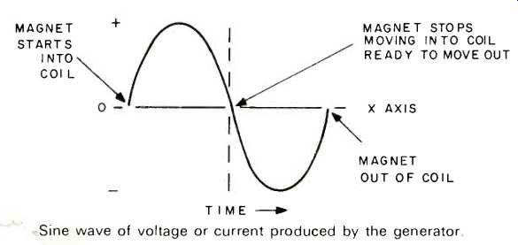
Fig. 13--Sine wave of voltage or current produced by the generator.
Back To Frequency
The faster the magnet is pushed in and out of the coil form, the more often the polarity of the voltage reverses, simply another way of saying that the frequency is higher. The amplitude or strength of the sine wave depends on the strength of the magnet, and on the number of turns of wire of the coil.
The voltage produced across the ends of the coil is sometimes referred to as an induced EMF. Any wire carrying an alternating current is surrounded by a varying magnetic field, capable of inducing a voltage in any nearby conductor, not necessarily a coil. That is why it is inadvisable to place power line cords (such as lamp cords) adjacent to FM antenna lead-ins, or to put a record player directly on top of a tape unit.
The combination of coil and magnet is known as a generator, an electromechanical device for producing a.c. It is eminently suitable for power line frequencies, such as 60 Hz, but purely electronic generators are used for the much higher frequencies required in broadcasting.
( Audio magazine, Jun. 1972)
Also see:
The Language Of High Fidelity—Part I (May 1972)
The Language of High Fidelity--Part III: Basic Electronic Components (cont.) (Aug. 1972)
The Language of High Fidelity--Part VII: The Basic High-Fidelity System (Dec. 1972)
The Language of High Fidelity--Part VIII (Feb. 1973)
Language of High Fidelity--Part XI (May 1974)
= = = =