by Alan G. Ogilvie
THIS ARTICLE describes the construction of a simple low-cost stereo preamplifier for use with magnetic cartridges. The project uses the minimum number of components and can be completed in one to two hours by anyone possessing the minimum of skill with a soldering iron.
A Signetics PA239 dual low-noise amplifier, or the equivalent, is the only active device used in the circuit. This device is a linear monolithic circuit featuring two identical matched 68-dB amplifiers designed for use with low-level signals in low-noise applications. Consequently, it is well suited for use with magnetic cartridges. An additional feature is an internal zero-regulated power supply which eliminates the need for i.f. or r.f. decoupling and allows the device to be powered from a single unregulated power supply. Channel separation at 1 kHz is typically 90 dB. The typical equivalent input noise voltage (100 Hz to 10 kHz) is 0.7 µV rms or 1.2 IN rms maximum, which gives a signal-to-noise ratio of 72 dB or 68 dB respectively, with a magnetic cartridge output voltage of 3 mV rms. The total harmonic distortion without feedback is typically 0.5 percent.
The schematic diagram and connection diagram are shown in Figs. 1 and 2 respectively. Figure 3 shows the circuit required to match the amplifier response with the RIAA recording characteristics. The measured response of the amplifier is shown in Fig. 4 with the theoretical response shown dotted for reference. The corner frequencies are specified at F, = 50 Hz; F, = 500 Hz, and F, = 2120 Hz. The lower corner frequency F, is determined by the capacitance C, and calculated from the formula:

(1)
where A, = the feedback gain 45 dB, or 178, at pin 3 and Z, = the input impedance, 2400 ohms, at pin 3.
Substituting in equation (1)

The value 200 µF was selected by the writer although the reader may wish to try 250 uF as an experiment.
The midband gain is determined by letting R1 = 33 ohms and calculating the value of R, from the formula

(2)
A voltage gain of 40 dB was selected as this allows a useful dynamic range and gives sufficient amplification for cartridges with outputs of 3 to 5 millivolts rms to drive most power amplifiers.
Substituting in equation (2)
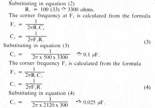
[3,4]
An additional capacitor C4 provides roll-off at high frequencies and is the compensation recommended by the manufacturer.
Printed circuit board layout is not critical with the PA239 as long as the input and output lines are kept separate. A suggested layout is shown in Fig. 5. Alternatively, a neat layout can be made with breadboard if printed circuit facilities are not available.
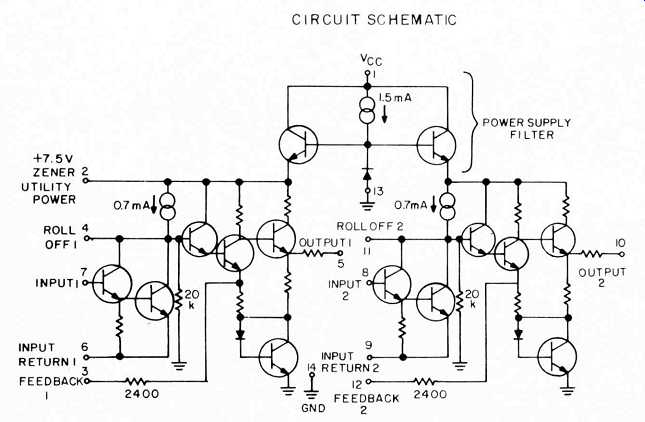
Fig. 1-Circuit schematic.
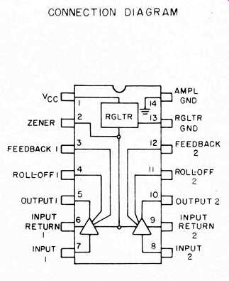
Fig. 2-Connection diagram.
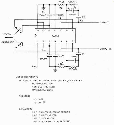
Fig. 3-Circuit showing RIAA compensation.
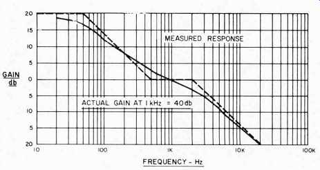
Fig. 4-Measured response of the amplifier.
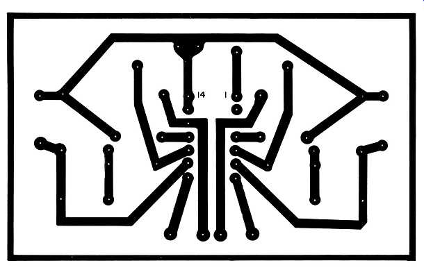
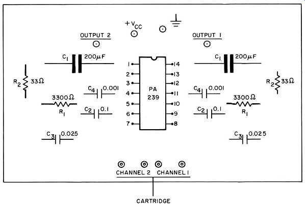
Fig. 5--Suggested layout.
Note that each channel of the stereo cartridge has two wires going to the input of each amplifier and that neither wire is grounded. You may have to separate two wires on your pick up terminal board as the majority of systems common one side of each channel, and then take it to ground/earth. If you do have to separate two wires, take care to connect them to the same side of the dual amplifiers, e.g. pins 3 and 12 or 8 and 7, or you will reverse a phase on the cartridge and reduce the bass response of your system. If each pair of wires from the cartridge is screened and maybe a third screens the two screened pairs, all three screens should be earthed near pin 14. Note also the absence of the usual 47k or 68k ohm damping resistors across the cartridge coils. These have been omitted as their insertion did not improve the circuit performance. The reader may wish to verify this with his own cartridge.
The supply voltage is not critical-any value between 9 and 15 volts at 22 milliamperes is satisfactory. In fact, the current drain on some amplifiers is less than 16 milliamperes and therefore a small battery could be used. Obviously, if a battery is used, the internal regulator is not an advantage, but the hum input is zero and the reproduction of low level signals is improved.
(Adapted from Audio magazine, Jun. 1974)
Also see:
How Phono Cartridges Work (Mar. 1982)
Phase Testing in Phono Cartridges (Mar. 1983)
Birth of a Spec? PHONO CARTRIDGE NOISE (March 1977)
Understanding Phono Cartridges (Mar. 1979)