Manufacturer's Specifications
FM Tuner Section
Mono Usable Sensitivity: 10.8 dBf (1.9 uV).
50-dB Quieting Sensitivity: Mono, 16 dBf (3.5 uV); stereo, 37 dBf (40 uV).
S/N: Mono, 75 dB "A" weighted; stereo, 70 dB "A" weighted.
Frequency Response: 30 Hz to 15 kHz, ±0.5 dB.
Selectivity: 65 dB.
Capture Ratio: 1.5 dB.
Image Rejection: 50 dB.
I.f. Rejection: 75 dB.
AM Suppression: 60 dB.
THD: Mono, 0.2 percent at 1 kHz, 0.2 percent at 100 Hz, and 0.3 percent at 6 kHz; stereo, 0.3 percent at 1 kHz, 0.3 percent at 100 Hz, and 0.4 percent at 6 kHz.
Stereo Separation: 42 dB at 1 kHz; 32 dB from 30 Hz to 15 kHz.
AM Tuner Section
Usable Sensitivity (Internal Antenna): 250 p V/m.
Selectivity: 30 dB. Image Rejection: 50 dB. IA.
Rejection: 40 dB.
Power Amplifier Section
Power Output: 20 watts/channel, 8 ohm loads, 20 Hz to 20 kHz.
Rated THD: 0.02 percent.
SMPTE-IM: 0.02 percent.
TIM: Less than 0.02 percent.
IHF-IM: Less than 0.02 percent.
Dynamic Headroom: 3.0 dB. Clipping Headroom: 1.5 dB.
Slew Factor: Higher than 50. Slew Rate: 15 V/uS.
Damping Factor: More than 50.
Frequency Response: Through "Lab" input, see text, 10 Hz to 70 kHz,-3.0 dB.
Preamplifier/Control Section
Phono Input Sensitivity: 0.5 mV.
Phono Overload: 270 mV at 1 kHz.
RIAA Response Accuracy: ±0.3 dB. Phono S/N: 75 dB.
High Level Input Sensitivity: 30 mV.
High Level S/N: 86 dB.
Frequency Response: 20 Hz to 20 kHz, ±0.5 dB.
Bass Range: ±10 dB at 50 Hz.
Treble Range: ±7 dB at 10 kHz.
Filters: Infrasonic, 15 Hz, 12 dB/octave; infrasonic phono, 15 Hz, 12 dB/octave, may be cascaded with infrasonic for 24 dB/octave; ultrasonic, 35 kHz, 12 dB/octave.
Audio Muting: -20 dB.
General Specifications
Dimensions: 16 1/2 in. (41.25 cm) W x 41 1/16 in. (11.72 cm) H x 9 1/2 in. (23.75 cm) D.
Power Requirements: Switchable between 50/60 Hz, 110/220 V.
Weight: 15 lbs. (6.82 kg) .
Price: $330.00.
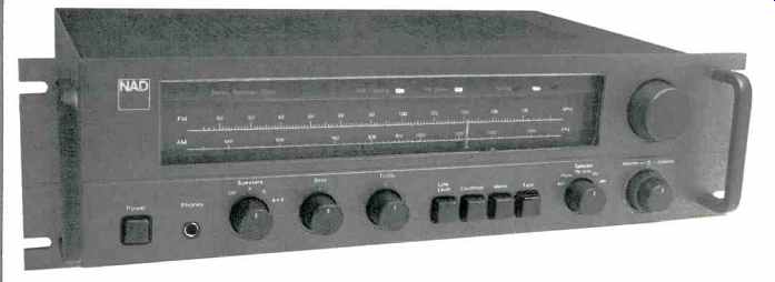
Every once in a while we run into an audio product which turns out to be unexpectedly excellent, the proverbial "sleeper." Running into two such products from the same company (and a relatively new company, at that) was really a surprise, but that is exactly what happened when we tested the new NAD 7020 receiver delivered by NAD (USA) Inc., a company that believes in concentrating on audibly superior performance rather than on superficial cosmetics or superb-looking numerical specifications. We had had an earlier opportunity to test one of the firm's separate components, their highly acclaimed Model 3020 integrated amplifier, and were extremely impressed with its measured as well as its sonic performance. The 7020 receiver clearly follows the same design philosophy as the earlier introduced separates. If anything, this NAD receiver entry is a bigger bargain for the budget minded audio enthusiast, if that is possible.
The all-black front panel of the NAD 7020 is fitted with a minimum of controls, but it does have those that are really necessary. A separate power on/off switch is at the lower left, adjacent to the usual stereo headphone jack. A rotary speaker selector switch follows, and next to it are bass and treble controls, each with a decent-stop at center of rotation for easy return to flat response. The cluster of four push-button switches that follows includes an audio muting switch (which NAD elected to identify as "low level"), a loudness circuit switch, a mono/stereo selector switch, and a tape monitor switch. The program selector switch is a rotary type and includes settings for AUX, Phono, FM Mute, FM, and AM. Concentrically mounted but separately operable volume and balance controls are at the lower right of the panel, and above them is the tuning knob.
The dial cut-out area of the receiver incorporates a linearly calibrated FM frequency scale with calibration marks at every 200 kHz, a long AM frequency scale, and a series of indicator lights located above these scales. Two of the indicator lights are shaped like arrows, each pointing in opposite directions.
These red lights tell the user in which direction to fine-tune as station signals are encountered on the FM dial. A green indicator light between the arrow indicators illuminates when precise center tuning has been achieved, and its intensity is a measure of signal strength. How's that for doing away with cumbersome and expensive mechanical meters that don't do the job nearly as well as these lights? A third indicator light turns on when a rear-panel switch is flipped to the so-called "soft clipping" position, about which more presently. Other facilities located on the rear panel include spring-loaded 75-ohm, 300-ohm and external AM antenna terminals, the required low- and high-level input jacks, tape out jacks, and a European-type DIN multi-pin connector for record/play connection of tape decks equipped with that type of plug.
Just below the antenna terminals is a three-position slide switch which offers a choice of de-emphasis values (75, 50 or 25 uS), making the receiver suitable for use in other parts of the world as well as for reception of Dolby FM broadcasts (with the additional aid of a separate Dolby adaptor). Jacks identified as "normal in," "preamp out," and "lab in" come next and require a word of explanation. Normally, the pair of wire jumpers supplied with the receiver would be connected from the "preamp out" terminals to the "normal in" jacks.
This choice of connections inserts an infrasonic and an ultrasonic filter in the signal path between the preamp and main amp. The subsonic filter cuts off below 15 Hz, while the ultrasonic filter has a cut-off point of 35 kHz. With these jumpers connected between preamp-out and lab-in, response extends well beyond these frequency extremes. The jumpers may, of course, be removed altogether if the user wishes to interpose a signal processing component such as an audio time-delay unit, a graphic equalizer, or a speaker equalizer such as those supplied by some loudspeaker manufacturers.
The soft-clipping switch mentioned earlier is located just above these in/out jacks, while to the right are two sets of color-coded spring-loaded speaker connection terminals. A pair of a.c. convenience outlets (one switched, the other unswitched) are located near the right end of the panel, along with a line fuse-holder.
Circuit Highlights
The NAD 7020 contains a rather sophisticated six-transistor circuit for the phono preamp section which is designed to interface correctly with :he impedance of phono cartridges.
The receiver combines modular circuit elements such as solid-state i.f. filters and ICs in the tuner circuitry to obtain good performance at reasonable cost. FM signals are amplified first through a junction FET-.i.f. amplifier. A total of three linear phase ceramic i.f. filters are used in the FM i.f. section. An integrated circuit phase-lock-loop multiplex decoder, supplemented by crosstalk cancelling circuitry, is used in the stereo FM-decoder circuitry.
The power-supply circuitry for the output stages of the NAD 7020 is of the very "soft regulation" design, supplying relatively high voltages to the output stages at 8-ohm loads and during musical waveforms of short duration, hence the very high dynamic headroom specification. An entirely separate supply circuit, operating from another secondary winding on the power transmitter, is used to provide regulated operating voltages for the preamplifier and tuner stages. The receiver is equipped with thermostatic circuit breakers which will interrupt sound to tie speakers if excessive output current flows through them. When that happens, it is necessary to turn the volume down, as there is no way for the user to defeat the protection circuit breakers externally.
FM Measurements
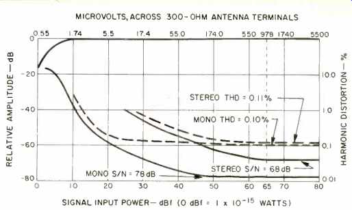
Fig. 1--Mono and stereo quieting and distortion characteristics, FM section.
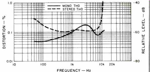
Fig. 2-Mono and stereo FM distortion vs. frequency, NAD receiver.
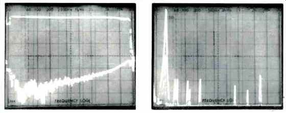
Fig. 3--Frequency response and stereo FM separation characteristics. Fig. 4--5-kHz
left-channel stereo FM output (tall peak at left) compared with right-channel
crosstalk and other components, including distortion.
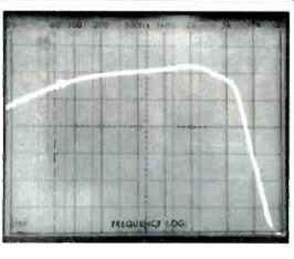
Fig. 5--Frequency response, AM tuner section.
The FM tuner section of the NAD 7020 exceeded the manufacturer's published specifications in every respect. Usable sensitivity in mono FM measured 1.7 pV (9.8 dBf), while in stereo it was 28.3 dBf or 8.0 pV. Fifty-dB quieting was reached with input signals of only 12.4 dBf (2.3 uV) in mono or 34.7 dBf (30 uV) in stereo, compared with the 3.5 uV and 40 uV claimed by NAD. Signal-to-noise ratio in mono, for strong 65-dBf signals, was an impressive 78 dB, while in stereo the S/N measured 68 dB, still somewhat better than the 65 dB claimed. Mono THD for a 1-kHz test signal was 0.1 percent, while in stereo it was very nearly as low with readings of only 0.11 percent.
These numbers, n and of themselves, do not tell the entire story concerning this remarkable tuner section. Referring to Fig. 1, a plot of noise and THD for mono and stereo, you can see that the THD level of 0.1 percent in mono is reached, or very nearly reached, with relatively low signal strengths so that an incoming signal of, say, 30 dBf (around 18 uV) provides as distortion-free reception as does a much stronger signal. Relatively speaking, the same holds true for stereo signals though, of course, greater signal strengths are demanded for equivalent performance levels.
Distortion remained extremely low in mono across the entire audio spectrum, with readings of 0.05 percent at 100 Hz and 0.075 percent at 6 kHz, the other two test frequencies at which THD is supposed to be reported. Again, these results are far better than claimed by NAD. As for THD in stereo, it too is amazingly low from around 200 Hz to above 6 kHz, as can be seen from the curve plotted in Fig. 2. The apparent rise in THD as test signals approached 10 kHz is, in reality, caused by the appearance of "beats" which appear in the output. Though undesirable, they are not, strictly speaking, harmonic distortion components. In any event, even taking these extraneous components into account, the distortion analyzer read a combined percentage of these components equal to 1.0 percent far better than we have measured on many receivers costing a good deal more. Stereo separation measured 49 dB at mid-frequencies, decreasing to 45.5 dB at 100 Hz and 35 dB at 10 kHz. A graphic plot taken directly by means of a sweep signal from our spectrum analyzer is reproduced in Fig. 3 and shows frequency response (upper trace) and separation. In this figure, sweep is from 20 Hz to 20 kHz and is logarithmic, while vertical spaces represent 10-dB increments.
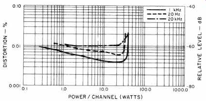
Fig. 6--Power output vs. distortion, both channels driven into 8-ohm loads.
In Fig. 4 the sweep has been altered and is now linear, extending from 0 <Hz to 50 kHz. The tall spike at the left represents the left-channel output of a 5-kHz signal modulating left only. Switching to a right-channel modulation, but continuing to read left-channel output, a second sweep was made. The spike within the tall spike is the actual 5-kHz separation between channels (approximately 40 dB), while the other spikes to the right of the display represent distortion components and sub-carrier components of the crosstalk signal observed at the left-channel output.
Capture ratio measured 1.3 dB, while AM suppression measured exactly 60 dB as claimed. Our sample had an alternate channel selectivity of 68 dB, as against 65 dB claimed. Image, i.f., and spurious rejection measured 55, 75, and 90 dB respectively. Stereo threshold as well as muting threshold both measured between 7 and 8 uV (around 22.5 dBf), a perfectly reasonable threshold setting for most listening conditions.
Even the AM frequency response, plotted in Fig. 5, was better than average, with the-6 dB cut-off points extending from 50 Hz to just beyond 5 kHz. The superiority of this AM section was later verified during our extended listening tests, and you would be amazed at how much better an AM set with reasonably good response out to 5 kHz sounds compared with the run-of-the-mill variety that cut off at around 2.5 to 3.0 kHz.
Amplifier Measurements
Impressed as we may have been with the excellence of the tuner section in such a low-cost receiver, our real amazement occurred when we began to measure the power amplifier section. At mid-frequencies this amplifier delivered exactly twice its rated power output per channel, or 40 watts into 8 ohm loads, before we observed a THD reading of 0.02 percent. Even more amazing, the same power output was observed for a test frequency of 20 kHz and for our SMPTE-IM tests, using 60-Hz and 7-kHz two-tone equivalent signals.
The power output available for 0.02 percent THD decreased to 32 watts at 20 Hz, but remember that this amplifier is officially rated (in terms of the FTC rule) at only 20 watts per channel! Figure 6 plots output power versus distortion for test frequencies of 20 Hz, 1 kHz, and 20 kHz.
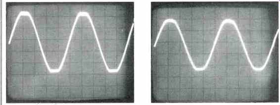
Fig. 7--Normally, clipping during overload of the NAD 7020 is sharply squared
off, as in most solid-state amplifiers (A). When the "soft clipping" circuit
is switched on, clipping resembles that of a tube amplifier (B).
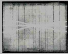
Fig. 8--Tone control range.
Using the IHF-prescribed test signal required for measuring dynamic headroom (20 mS of a 1-kHz burst followed by 480 mS of the same frequency at lower amplitude), we observed IHF dynamic headroom of 3.2 dB. This means that for short-term musical peaks, the amplifier could be expected to deliver around 41.8 watts of power per channel into 8-ohm loads before any evidence of clipping would occur.
Speaking of clipping, we wanted to find out just what the "soft clipping" circuit of the NAD 7020 was all about. Therefore, with this switch in the off position, we drove the amp hard into clipping with a 400-Hz sine wave tone; the output waveform was that shown in the 'scope photo of Fig. 7A. The sharp cornering of the waveform as it enters the region of clipping is clearly evident. It is this sort of clipping that produces harsh power-supply buzz sounds as well as even-order distortion components that prompt some people to talk about the harsh sound of solid-state amplifier designs.
Without changing input signal levels in any way, we now moved the rear-panel switch to the soft clipping on setting, and the waveform immediately took on the appearance shown in the 'scope photo of Fig. 7B. Notice that the waveform near the peaks is now softly rounded. The appearance of the waveform of Fig. 7B should bring back memories of tube amplifiers to those readers who can remember them and who were involved in audio "way back then." We attempted to measure IHF-IM but found that even using our spectrum analyzer to detect the unwanted spurious components generated during these twin-tone tests, such components were too low to be detected, meaning that the IHF-IM was well below the 0.02 percent claimed by NAD. Preamplifier and Control Section Measurements Range of the bass and treble tone controls provided on the 7020 is shown in the sweep frequency plots of Fig. 8. Sweep is again logarithmic, from 20 Hz to 20 kHz in this presentation, and vertical sensitivity of the display is 10 dB per division.
Note how the manufacturer has elected to shelve the response of these controls when they are in their extreme positions instead of allowing the boost (or cut) to continue to increase with increase or decrease of frequency. This is a wise approach for use in a receiver of limited power output and acts to prevent overly enthusiastic (but tone deaf) users from overloading the amp by turning everything fully clockwise! Before going any further we wish to commend the people at NAD who wrote the specifications. They are among the first to fully utilize the new IHF Amplifier Measurement Standards. We have been using these standards since shortly after they were approved, and readers will, for the first time, actually be able to compare our S/N and input sensitivity results with those claimed by the manufacturer without having to perform any mathematical manipulations or conversions. For example. NAD claims a S/N ratio in phono (properly referred to 5-mV input and 1-W output) of 75 dB. We measured a superb 80 dB, using the same input and output references. They claimed 86 dB of S/N for the high-level inputs, and that's precisely what we measured. Phono overload at 1 kHz measured 280 mV against a claimed 270 mV. With the jumpers connected to the "normal" inputs, high-level frequency response was down 1 dB at 16 Hz and 35 kHz; 3 dB down points were at 14 Hz and 40 kHz, indicating the swift takeover of those permanently in-circuit 12 dB/octave filters (not the phono filter, incidentally).
Use and Listening Tests
The NAD 7020 is, in our opinion, one of the best sounding receivers in its power and price class that we have ever had the pleasure of auditioning. Whether we listened to FM or to our own selected and demanding discs, we had to repeatedly remind ourselves that this receiver is nominally rated at only 20 watts per channel and that its suggested retail price is barely more than $300.00. We can definitely attest to the fact that the "soft clipping" feature does reduce audibility of clipping significantly. However, we had to go some to cause the amp to clip in the first place, since we were using relatively high-efficiency ported speaker systems to test the unit and even we have an SPL tolerance limit. Of course, when we wore ear protectors and continued to increase loudness (and gain) levels beyond first clipping, eventually we could hear the overload distortion even with the soft clipping circuit activated. We wouldn't venture to guess what power level we were at when that happened.
Most of our listening was conducted under more sensible conditions, and we found the NAD 7020 to be a receiver that delivers the kind of good sound we like to live with. FM stereo reception was superb, and accurate FM tuning was easily done thanks to NAD's unique tuning indicators. The low image-rejection figures offered by this tuner may cause some problems for those living in areas where transmission outside the FM band has a way of creeping into the public frequencies (e.g. if you live near an airport control tower), but we encountered no such difficulties in our difficult listening locale. If NAD can maintain the quality of the 7020 at the level which we encountered in this first production sample, they clearly have a winner on their hands, both in performance and in price.
-Leonard Feldman
(Source: Audio magazine, Jun. 1980)
also see:
NAD 7130 Receiver (Sept. 1985)
NAD 7220PE Receiver (Sept. 1987)
NAD 7400 Receiver (Equip. Profile, Aug. 1989)
= = = =