
Manufacturer's Specifications
Preamplifier:
Frequency Response: 5 Hz to 30 kHz, ±0.25 dB; -3 dB below 1 Hz and above 100 kHz.
Maximum Output: 60 V (into high impedance).
Harmonic Distortion: 0.01% at 2 V rms output, 20 Hz to 20 kHz; mid band, typically 0.002%.
SMPTE and IHF IM: 0.002% at 2 V rms equivalent.
Input Sensitivity: Phono (MM or MC), 0.125 mV; high level, 35 mV.
Phono Overload: 300 mV at 1 kHz; 1V at 10kHz.
S/N Ratio: Phono (MM or MC), 86 dBA; high level, 90 dB below 1-V in.
MM Phono Input: Capacitance, 40 pF; impedance, selectable, 10, 30, 100 ohms, 10 or 47 kilohms.
Dimensions: Two pieces, each 19 in. (48.3 cm) W x 5 1/4 in. (13.3 cm) H x 10 1/4 in. (26 cm) D, plus 15/8 in. (4.1 cm) forward extension for handles and 7/8 in. (2.2 cm) projection for rear fittings.
Weight: 31 lbs. (13.9 kg).
Price: $3,450.00.
Amplifier:
Power Output: 65 watts per channel, 4-, 8- or 16-ohm loads, 20 Hz to 20 kHz, 1% THD
Power Bandwidth: 10 Hz to 60 kHz; 15 Hz to 30 kHz at 1% THD
Slew Rate: 12 V/µS
Input Sensitivity: 950 mV.
Dimensions: 19 in. (48.3 cm) W x 7 in. (17.8 cm) H x 16 1/2 in. (41.9 cm) D, plus 1 5/8 in. (4.1 cm) forward extension for handles.
Weight: 51 lbs. (22.9 kg).
Price: $1,995.00.
Company Address: 6801 Shingle Creek Pkwy., Minneapolis, Minn. 55430.
Audio Research's SP-10 is their most-evolved, top-of-the line preamplifier. The D-70 is the smallest of three models that represent the company's current thinking on tube power amplifiers.
Among the design principles involved in these units are the use of 6DJ8 dual triodes, "Wonder Cap" polypropylene coupling and bypass capacitors, new signal circuitry, elaborate power-supply regulation, use of superior-sounding wire in the signal and power-supply construction, and new output transformer designs.
The SP-10 consists of two parts, the preamp itself and a separate power supply; both are 19-inch rack width. Interconnection is via a 1-meter cable with gold-plated "aircraft type" connectors. Rotary controls on the preamp front panel are, from left to right: "Gain," "Balance," "Mode," "Input" selector, phono loading "Impedance," and phono "Cartridge" selector. Toggle switch controls include: Bypass/ normal, high/low gain, mute, and tape monitor. Also on the lower center portion of the front panel are two green LED indicators, one to indicate power on, and the other, by alternately flashing dim and bright, to indicate automatic mute mode. On the rear panel are the usual signal connectors, power-supply connector, and a pair of binding posts for connecting the chassis to signal common-a useful feature in rack installations, to break ground loops.
Controls on the power supply's front panel are two toggle switches for preamp and outlet power; green LED indicators show when these are switched on. Rear-panel features : include the three-wire a.c. power cord, a connector for voltages to the preamp. line and high-voltage fuses, and one unswitched and three switched three-wire a.c. outlets.
The third or ground wire of the power cord goes to the third wire of the a.c. outlets and to the chassis and signal ground.
Since the preamp and power amp both have third-wire ground a.c. plugs, I would recommend grounding only one of the units, preferably the power amplifier, to the a.c. line via the power plug, aria isolating the other units (and any other equipment in one's system). One way to do this is by equipping the other components having three-wire power cords with ground-lifter adaptor plugs. This will avoid unwanted ground loops between units.
The D-70 power amplifier is also rack width. Its one front panel control is a toggle switch for power. Two green LEDs show when power and output-tube screen voltage are on, and also serve as fuse-out indicators. Line and screen supply fuses are easily accessible on the front panel. (An aside on what a screen grid is: It is an accelerating grid, in pentode and beam power tubes, which gives the tubes high gain, high output impedance, and low saturation voltage drop, enabling higher power to be obtained from a given high-voltage supply than triode output tubes can.) On the rear panel are the power cord, two signal input jacks, and two four-terminal barrier strips for output connections for 4-, 8-, and 16-ohm loads.
Two output transformers and the main power transformer are mounted behind the front panel. The bulk of the circuitry, including the output tubes and filter capacitors, is on one large p.c. board taking up the remainder of the top area of the chassis. A perforated screen covers the components on the p.c. board, keeping one from possible severe burn and shock hazards. The p.c. board and parts quality are first-rate. The boards have been drilled with many holes to let air flow up through them in the area of large heat-dissipating parts.
I find the Audio Research pieces very attractive and functional in appearance.
Preamplifier Circuitry
The signal circuitry in the SP-10 is a departure from past Audio Research preamps in that the tubes used are 6DJ8s, instead of 12AX7s, and the phono circuit is more elaborate.
Overall, there are two blocks of gain, consisting of a phono preamp/equalizer and an output amplifier, yielding minimum circuit topology regarding number of amplifiers in the signal path. The first stage acts as a grounded-cathode (i.e., usual connection) amplifier which is RC-coupled to the second stage. Operation of this second stage is as a cascode connection of two tubes, the bottom of which is a grounded cathode amplifier and the top, a grounded-grid amplifier.
Resultant characteristics of this combination are high gain, linearity and speed. These are appropriate to the second stage, since signal level is higher than in the first stage.
Output of this second stage is direct-coupled to the third stage, which operates as a grounded-plate or cathode follower amplifier, yielding low output impedance and high E. linearity for driving the outside world (tape output), the mode, volume and balance network, and the RIAA feedback network.
The output amplifier is of more usual topology and more like previous Audio Research circuits. It consists of a grounded-cathode first and second stage and, again, the cathode-follower output stage. Frequency-independent negative feedback is applied around the output amplifier for wide frequency range, low distortion, and low output impedance.
In the phono preamp, both elements of each 6DJ8 are connected in parallel. This gives the advantage of lower stage noise, which is most important in the first stage.
Additionally, lower plate-resistor values, along with higher currents than were formerly used with 12AX7 tubes, give higher speed operation of the overall circuit. In the output amplifier circuit, single halves of 6DJ8s are used in the first and second stages, whereas two paralleled elements are used in the cathode-follower output stage.
Power-supply distribution and regulation is more elaborate in the SP-10 than any other preamp that I am aware of.
To supply regulated and low-noise heater voltages to the preamp tubes, the SP-10 uses two transformer windings, each with its own bridge rectifier and filter capacitor, plus a total of six, three-terminal TO-3 power regulators. The basic high-voltage supply starts out with a full-wave, bridge-rectified, 550 V d.c., terminating in 100 µF of filter capacitance.
The high-voltage regulator provides an output of 305 V d.c. and is a hybrid circuit using two triode-connected 6L6 output tubes connected in parallel as the series-pass element. A 12AT7 tube, with the two halves paralleled, is used as a voltage amplifier to drive the grids of the series-pass tubes. The error amplifier is a solid-state op-amp whose output drives the grids of the 12AT7 tube. This regulator is in itself a low-noise, highly regulated source of d.c. voltage.
Four additional regulators, consisting of op-amp error amplifiers and Darlington-connected series-pass transistors, furnish 293 V d.c. to each channel's three phono stages and three output amp stages. The 293 V d.c. from the phono first-stage regulator is dropped down to +43 V d.c. in a two transistor discrete regulator, and, finally, a circuit similar to the 293-V regulators supplies +32 V d.c. to the grids of the upper phono second-stage tubes! Polypropylene capacitors are liberally used as bypass elements in all the regulator circuitry.
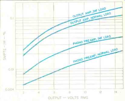
Fig. 1--SMPTE-IM distortion, SP-10 preamplifier.

Fig. 2--Phono EQ error with IHF load at tape out, SP-10 preamplifier.
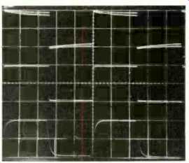
Fig. 3--Response of SP-10 phono section to pre-equalized square waves. Top,
40 Hz with 90 and 10 kilohms; middle, 1 kHz with IHF load; bottom, 10 kHz with
IHF load.
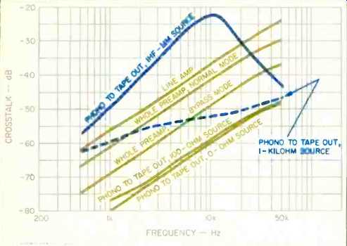
Fig. 4--Interchannel crosstalk (right to left) vs. frequency, SP-10 preamp.
Line-amp crosstalk measured with 1-kilohm source and high-gain setting, volume control fully clockwise. Whole-preamp measurements made with high-gain setting, 0-ohm source, and volume control at 12 o'clock.
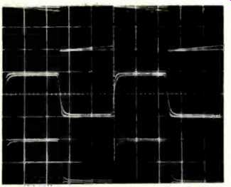
Fig. 5--Response of SP-10 line section to square waves. Top, 20 Hz with 90
or 10 kilohms; middle, 20 kHz with normal and IHF loads; bottom, same as middle
but volume control at 12 o'clock.
A time-delay automatic mute circuit is provided to prevent gross turn-on/turn-off surges to connected power amplifiers.
Delay time upon turn-on is about 2 1/2 minutes. Automatic mute upon preamp turn-off is rapid enough to prevent output surges. Since the SP-10 really takes longer than 2 1/2 minutes to settle out and stabilize, it is recommended that the "Mute/Operate" switch be placed in "Mute" (which actually shorts the preamp main outputs) when the preamp is turned on or off. One should wait about 5 minutes before switching the muting switch to "Operate" after turning the unit on. This is particularly important for high-power transistor pc /tier amps and is not so important for tube power amps. The auto-mute circuitry will also mute when the preamp is on and operating if the a.c. line voltage drops below about 100 V a.c., preventing really gross output surges that would occur if the power-supply regulators dropped out of regulation-which would happen at about 90 V a.c.
A word about the gain structure and signal path of the SP 10: The input noise of the phono stage is quite low for tube circuits, allowing a satisfactory S/N for medium-output moving-coil pickups without step-up devices. Further, the total maximum preamp gain of about 72 dB with the gain switch in the high position is entirely adequate for enough system acoustic output. The SP-10 was really designed with just this in mind. A more normal preamp gain of 60 dB is possible, for higher output moving-magnet cartridges, with the gain switch at low.
A nice purist feature of this preamp is a bypass switch which connects the output of the phono preamp directly to the volume control. This eliminates the switches and wiring of the selector, tape monitor, gain, and balance controls from the signal path. Under these conditions, one has full 72-dB gain (volume controllable, of course), committed phono operation, and no balance or mode functions. A related feature is the use of high-conductance rotary switches for phono input-resistance loading and "Phono 1/Off/ Phono 2" selection.
Amplifier Circuitry
The first stage of the D-70 power amp is a push-pull, or differential, voltage amplifier using the two halves of a 6DJ8 tube. Often, such a first stage performs the phase-inversion function by having one input-tube grid grounded. The D-70 uses a single half of a 6DJ8 as a "plate-follower" inverting amplifier fed back to unity gain to feed one grid of the input stage, while the other grid is fed by the input signal itself.
Having established a solid push-pull or balanced signal out of the first stage, we proceed to the second stage, which I would best describe as a cross-coupled output-driver stage. This composite second stage uses two 6DJ8 tubes so arranged that the second of these tubes, whose plate signals are the outputs which drive the output-tube grids, has push-pull grid drive via direct coupling from the output of the first stage. Combination direct and capacitor coupling from the first stage is also used to drive the grids of the second stage's first tube, which is used as a cathode follower. The cathodes of this tube are cross-coupled to the cathodes of this stage's second tube. This ensures that each phase of the final output has both phases of the stage input involved in creating it. Such an arrangement yields better push-pull balance in the output phases, despite any drift and aging of the tubes involved.
The output of the second stage is capacitor-coupled to the grids of the output tubes, a pair of 6550 beam power tubes. Regulated fixed bias is used in this grid circuit. The primary winding of the output transformer is not screen tapped as in ultralinear operation, because the output tubes are operated as pentodes with a regulated screen-supply potential of +325 V d.c. The B+ supply for the output-tube plates is 430 V; it is unregulated but has enormous filter capacitance for tube circuits, some 1,000 µF of electrolytic bypassed with 2 of polypropylene.
Since the final intent of this design is to have balanced push-pull feedback from the output back to the input stage, the 4-ohm tap of the output transformer secondary winding is grounded, causing the 0and 16-ohm taps to have equal but opposite-phase voltages in respect to ground. To complete the picture, local output-stage negative feedback of about 6 dB is obtained by connecting the output-tube cathodes through 1-ohm, current-monitoring resistors to the "0" and "16" output taps. Having the 4-ohm instead of the usual 0-impedance tap grounded offers little practical difficulty in driving speakers, but one mustn’t have a common ground between the input ground and the 0-ohm tap during use or measurement, or one-half of the output transformer secondary will be shorted out.
The main regulator in the power supply for the screen supply is a hybrid design like that in the SP-10. A triode connected 6550 tube is used as a series-pass element. Input to the plate of the 6550 is 570 V, obtained from a separate winding and rectifier and capacitor system added to the 430 V for the output-stage plate supply. A 12AX7 tube with elements paralleled is used as a voltage amplifier to drive the control grid of the 6550. The error amp is a TLO-71 op-amp. A solid-state "zener-follower" regulator is connected between the raw 570-V and regulated 325-V output of the screen regulator, to provide a regulated 430-V supply to the plate resistors of the second tube of the amplifier driver stage. A full electronic-feedback regulator-with Darlington connected, transistor series-pass elements and an op-amp error amplifier-is fed from the screen supply to deliver a regulated 327 V to the plate resistors of the amplifier's first stage and the plates of the first tube in the second stage.
Another winding on the power transformer is bridge-rectified and capacitor-filtered to-56 V, then electronically regulated to 42 V for the output-tube bias supply. This regulator uses Darlington-connected series-pass transistors, with a one-transistor error amplifier. The driver stage, output tubes, and screen-regulator series-pass tube heaters are a.c.-powered. The rest of the tube heaters are fed with regulated d.c.
As in the SP-10, the various regulator circuits in the D-70 power supply are liberally bypassed with polypropylene capacitors. A useful feature of this power supply is a circuit designed to prevent excessive a.c. inrush current upon amplifier turn-on. A thermistor, placed in series with the power-transformer primary winding, is bypassed by a relay after a suitable time delay. Control voltage for the relay coil is from the rectified d.c. for the tube heater supplies. Since heaters have a low resistance when cold, the amp's turn-on delay is essentially the time these heaters take to warm up to a higher resistance, allowing this d.c. voltage to rise and pull in the thermistor-shorting relay coil. Novel-and much easier on components.
Another interesting aspect of the power supply is an interconnection of the regulated bias-supply output and the 12AX7 in the screen supply. If, for some reason, the bias supply drops below some threshold value which would cause excessive output-tube dissipation, the screen voltage is also dropped, keeping dissipation in line.
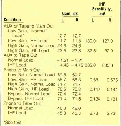
Table I--Gain and IHF sensitivity, SP-10 preamplifier.
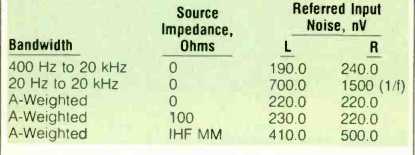
Table II--Phono noise, referred to input, SP-10 preamplifier.
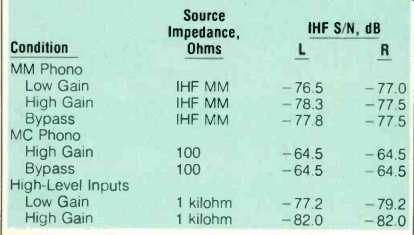
Table III--Phono and AUX IHF signal-to-noise ratios, SP-10 preamplifier.
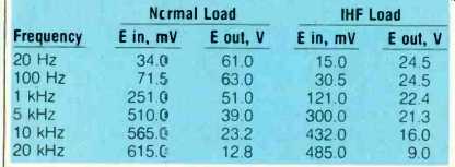
Table IV--Phono overload vs. (left-channel) frequency and loading, SP-10 preamplifier.
Preamplifier Measurements
Interested readers are referred to my review of the Spectral DMC-10 in the September 1983 issue of Audio for helpful comments or IHF measurements. With this in mind, I won't repeat them here.
Circuit gains and IHF sensitivities of the Audio Research SP-10 were measured first (Table I). Next, phono noise was measured for various bandwidths, weighting, and source impedances (Table II). IHF signal-to-noise ratios were measured for phono and high-level inputs, and results are presented in Table III.
Phono THD plus noise was measured at output levels of 2 and 5 V rms with an IHF load. At 2-V output, for the worse (right) channel, it was 0.1% at 20 Hz, 0.011% at 1 kHz, and 0.01% at 20 kHz. At 5-V output, it was 0.26% at 20 Hz, 0.024% at 1 kHz, and 0.02% at 20 kHz.
The SMPTE-IM distortion was measured as a function of output level and phono preamp loading, and results are shown in Fig. 1. Two-tone CCIF distortion, with frequencies of 10 and 11 kHz (equal amplitude), was measured at 3-V rms output from the phono preamp and was found to be less than 0.01%. Phono overload versus frequency and loading at tape output is enumerated in Table IV. Relevant conditions are: Volume control full counterclockwise, tape monitor to "Source," and bypass switch to " Normal." The basic limitation at low frequencies is onset of clipping of the negative half-cycle of the output waveform. At high frequencies, a stewing aberration near the peak of the negative half-cycle is the limitation.
Phono equalization error versus frequency for a resistive source is plotted in Fig. 2. A test that I always look at in phono preamps (although not always reported), is how symmetry of a 1-kHz pre-equalized square wave varies with output level. This circuit looks just about perfect up to ±5 V output; at ± 10 V output, the negative half-cycle has some tilt while the positive half-cycle is still straight. This is very good for this measurement. A 'scope photo of various pre equalized square waves applied to the phono input is presented as Fig. 3. The top trace in this figure shows the effect of the 10-kilohm part of the IHF load causing more low frequency tilt.
Phono input impedance could be represented to a satisfactory degree of accuracy by a resistance of 46.8 kilohms in parallel with 300 pF. Phono crosstalk was looked at with a short or zero-impedance source on the input of the undriven channel, which is the way I've usually measured this. One drives one channel with a pre equalized sine wave and measures the leakage into the undriven channel in respect to the driven channel's output.
Results are very good with the zero-impedance source and are plotted in Fig. 4.
Something devious within urged me to try terminating the undriven channel with my IHF moving-magnet noise-source impedance, which is a parallel network of a 500-mH inductor in series with 1,000 ohms and 125 pF of capacitance. As can be seen, this made matters much worse. The reason for the peaking at about 10 kHz is the resonance of the 500-mH inductor with the shunt capacitance of 125 pF in the IHF source and 300 pF in the SP-10. I don't know if this is unique to this preamp, and I suspect it's not, but it does suggest a possible reason why moving-magnet pickups with high inductance don't seem to have imaging and dimensionality as good as the better moving-coil pickups, which have much lower high-frequency electrical impedance. Crosstalk of the phono and line sections of this preamp are both in phase, which means that the leakage or crosstalk signal is positive going for a positive-going pre-equalized square-wave edge in the driving signal.
To investigate how much phono crosstalk might be degraded by a moving-coil step-up transformer, which transforms the pickup impedance upwards by the step-up impedance ratio of the transformer, I measured phono crosstalk for terminating impedances of 100 and 1,000 ohms.
Considering the various moving-coil impedances and step-up ratios of transformers, 1 kilohm is a reasonable value but not worst-case. This information is plotted in Fig. 4 along with crosstalk for the line section and a few combinations through the whole circuit. What does it all mean? A moving coil pickup fed in directly will have superior channel-to channel electrical crosstalk, virtually that of a zero-impedance source, while a moving coil fed in via a step-up transformer might have the crosstalk of a 1-kilohm source, which is considerably better than the crosstalk of most pickups themselves. High-inductance moving-magnet pickups will likely have crosstalk similar to that of the IHF source, which is on the order of the high-frequency crosstalk of most pickups.
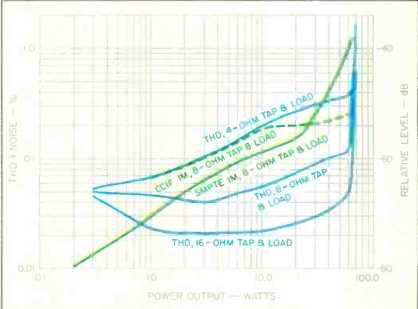
Fig. 6--Total harmonic distortion plus noise, SMPTE IM, and CCIF IM vs. power
output, channel 2, D-70 amplifier.
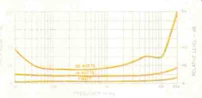
Fig. 7--Total harmonic distortion plus noise vs. frequency and power, channel
2, D-70 amplifier, with 4-ohm tap and load.
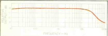
Fig. 8A--Frequency response of D-70 amplifier, 16-ohm load.
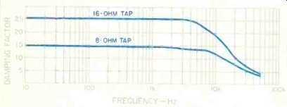
Fig. 8B--Damping factor vs. frequency, D-70 amplifier.
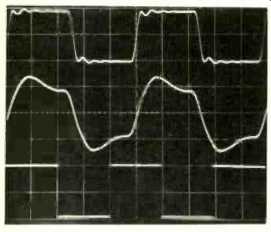
Fig. 9--The effect of a difficult load on the D-70 at high frequencies is
shown by the difference in the 10-kHz square wave into a 16-ohm load (top)
when the same load is paralleled by 2µF (middle). The bottom trace is 50 Hz
into a 16-ohm load.
These pure-phono-stage crosstalk considerations are somewhat complicated by the line section of the SP-10. For instance, in the bypass mode there is lower overall crosstalk than in the normal mode. The final point here is that the whole preamp will have better crosstalk with moving-coil pickups than with moving-magnet pickups of high inductance. It is to be emphasized that I'm not specifically condemning the SP-10 on this count, as further investigation may well reveal that other preamps have similar behavior.
Figure 1 shows the SMPTE-IM distortion for the output amplifier. My "normal" load is the parallel combination of the Sound Tech distortion meter input, 'scope, and interconnecting shielded cables. Resistance is about 90 kilohms, and capacitance is about 250 pF. The IHF load is 10 kilohms in parallel with 1,000 pF. Total harmonic distortion plus noise was measured as a function of frequency, output level, and loading for the line amplifier. At 2-V rms output, it was less than 0.01% with either load. At 5-V output, it was 0.013% at 20 kHz with normal load and 0.02% with the IHF load. Two-tone CCIF equal-amplitude 10and 11-kHz distortion was less than 0.01% with either load at 3-V rms output.
Various square-wave responses of the output amplifier are illustrated in Fig 5. The top trace shows the effect on low-frequency tilt of decreasing the load from 90 to 10 kilohms. The middle trace shows the effect of adding the IHF load to the normal load on a 20-kHz square wave (the smaller amplitude wave is with the IHF load). The bottom trace shows the effect of the normal versus IHF load with the volume control at 12 o'clock (the faster waveform with some overshoot is with the normal load). Rise-time of the output amp with the volume control fully clockwise was 1.4 µS with normal load and 2.5 uS with the IHF load.
Slewing could be induced in the output amp and mostly occurred in the plus-to-minus transition of a pulse or square wave. At 35-V peak-to-peak output, it was 20 V/µS for the normal load and-6 V/uS for the IHF load. The reason for slewing in the negative direction is that single-ended follower circuits can't take a capacitive load in the negative direction faster than the cathode or emitter resistor can discharge the capacitance. Speed in the positive direction is higher because the follower device is actively turning on and becoming a lower dynamic impedance.
Output impedance of the phono function at tape output was about 1 kilohm. Output impedance at the main outputs was 840 ohms for the right channel and 965 ohms for the left. The AUX input impedance was about 59 kilohms shunted by 150 pF on low gain and 180 pF on high gain.
Amplifier Measurements
First thing done to the D-70 was to measure its bias and balance conditions. Output-tube idling current was about 60 mA for both channels. Both channels were set to 65 mA per Audio Research's recommendation. The d.c. balance of the front-end was close but was set right on.
I must say that setting output-tube bias by oneself is a bitch in this design. I had to measure the voltage drop across 1-ohm sampling resistors which have terminals on the p.c. board near the hot output tubes. Holding two meter probes on these terminals with one hand in order to have the other hand available to adjust the bias pot is a bit of a trick. Have someone else help with this if you can.
When attempting to set the a.c. balance controls for minimum second-harmonic distortion, I noticed that the second couldn't be eliminated on the 4-ohm taps but could be on the 16-ohm taps. The a.c. balance controls were set to null out the second harmonic at 10-watts output, 1-kHz, 16 ohm taps. Harmonic distortion plus noise was then measured as a function of frequency and power with 4-, 8-, and 16-ohm loads on their respective output taps. Harmonic distortion versus power at 1 kHz for 4-, 8-, and 16-ohm loads, and SMPTE and CCIF distortion with 8-ohm loads, are shown in Fig. 6. Harmonic distortion versus frequency for the 4-ohm tap is shown in Fig. 7. Note that distortion on the 8- and 16-ohm taps will be lower than shown in Fig. 7.
The reason for differences in distortion on different output taps is because the coupling in the output transformer between secondary windings is somewhat less than perfect. In a recent discussion, Bill Johnson of Audio Research said this phenomenon was less prominent in the higher power (and cost) D115 and D250 amplifiers, which implies better coupling in their output transformers. Some people have reported better sound from Audio Research tube power amps on the 16-ohm taps even though their speaker impedances were lower than 16 ohms. This may be related to better circuit balance affecting sound on the 16-ohm taps. Unfortunately, I didn't try this when listening to the D-70. (Postscript: As I was finishing typing this review, I started to listen to the D-70 on the 16-ohm tap with the Infinity RS IIa speakers and find that it sounds smoother and less offensive that way.) Voltage gain of the D-70 on the 8-ohm taps loaded with 8 ohms was 25 x , or 27.9 dB, which is close to "normal" power amp gain of 26 dB. IHF input sensitivity on the 16 ohm taps loaded with 16 ohms was 118 mV (channel 1) and 116 mV (channel 2). Measured rise-time on the 16-ohm taps was about 4.5 µS at 5-V peak-to-peak output level. Running the amp up to clipping with a 10-kHz square wave yielded a large-signal rise-time of 5µS. This is a good quality for an amp to have, approximately the same small- and large-signal rise-times.
Frequency response at the 1-watt output level and damping factor versus frequency are shown in Fig. 8. A 'scope photo illustrating square-wave responses is shown in Fig. 9.
The top trace is 10 kHz into 16 ohms. (The nature and degree of ringing was not materially different on the other output taps.) The middle trace is with 2 across the 16 ohm load. Bottom trace is at 50 Hz and shows excellent low frequency response. Finally, dynamic headroom measured out at about 0.16 dB with both channels operating into 16 ohm loads. Clipping headroom was about 0.32 dB. Use and Listening Tests Equipment used in evaluating the SP-10 and D-70 included an Infinity air-bearing turntable and arm using a Koetsu EMC-1B cartridge; Fidelity Research XF-1 Type M moving coil step-up transformer; Marantz Model 9, Dyna Stereo 35, and Acrosound 20-20 power amplifiers; Audio Research SP-3 and GC/BHK developmental tube reference preamp; Infinity RS II and RS IIa and Magneplanar loudspeakers, and always, Stax SRX Mk Ill headphones.
Early on, the SP-10 was compared to the tube reference preamp using Marantz 9s to drive the Stax headphones via the Stax SRD-7 power supply and step-up transformers.
(Note: I used the FR transformer only with my tube reference preamp.) The sound of the SP-10 was, by comparison, not as spacious and airy by an appreciable margin. Spectral balance, harmonic structure, and revelation of detail were very good with the SP-10. One observer characterized the SP-10 as "spatially compressed" by comparison. Next, the D-70 was listened to in the same setup, using the reference preamp as the signal source. Compared to Marantz 9s, the D-70 sounded noticeably less open and spacious and was slightly hard and metallic-sounding in the upper midrange.
Another interesting listening experiment was to interpose one power amplifier in series with the other and then to reverse the order. More specifically, the reference preamp was fed via a dual 50-kilohm volume control into the input of the D-70. The output of the D-70 was loaded with 50 ohms on the 4-ohm output tap and then fed into the inputs of the Marantz 9s, which drove the Stax phones. The 50-kilohm level control was adjusted so that overall level, as adjusted with the M-9 input level controls, was the same as when the M-9s were used alone and with the M-9 level controls at the same degree of rotation. In effect, I was inserting the D-70 as a gain-of-one device and noting how the sound changed as a result of this insertion. The sound of this arrangement was less spacious and generally sounded more like the D-70 alone. Instrumental texture was-good, and 'the hardness of the D-70 alone was less noticeable. The order was then reversed, with the Marantz 9s first, attenuated by the 50-kilohm level control and loaded with 50 ohms on the 4 ohm taps, and then the D-70 driving the Stax phones.
Interestingly, the sound took on the character of the M-9s, being more open and spacious. This means that neither amplifier is perfect; otherwise, there would be no change in the sound wherever a perfect amplifier was inserted in series with an imperfect one.
I personally prefer the sound of the Marantz 9s to this particular D-70 sample, both in headphone listening and on the speakers I have used. Another observer, who uses Magneplanar speakers and Quicksilver tube amps, said of the D-70: "Punchy, very powerful-sounding for its rating, dimensionally flat, clear, metallic-sounding in upper ranges, less apparent low bass." I have heard very good reports about the D-70 in other situations from people whose listening ability I respect.
The SP-10 I find highly listenable and have used it extensively in my system and in other systems. I took it over to the house of the same friend who has the Magneplanars. On his system, the SP-10 produced excellent resolution and detail, with good spectral balance. We compared it to an old Audio Research SP-3, which sounded more spacious and three-dimensional, but the SP-10 was more textually honest.
A few caveats on the SP-10 and D-70. I can generally judge preamps' susceptibility to external r.f. interference by how much of a thump I get at playing levels on phono function when I turn my turntable on and off. The SP-10 makes a horrendous crack when I do this. I definitely have to mute it when turning on my turntable. Also, when my kitchen oven cycles on and off, I get a zap in my stereo when playing records with the SP-10. Other preamps, under the same conditions, produce less or no interference. The D-70 has a moderate turn-off thump, which is odd for a tube power amp.
In conclusion, I feel the Audio Research components reviewed here are both attractive and functional pieces. I would wholeheartedly recommend the SP-10 as a "state of the available or purchasable art" preamp. My less enthusiastic feelings about the D-70 may be related to my personal preferences and possibly a less than representative sample. On this count, I would have to say, go listen to the D-70 in as many situations as you can and judge for yourself.
-Bascom H. King
[AUDIO magazine/June 1984]
Also see: Audio Research M-300 Amplifier (Nov. 1988)
Audio Research LS3 B Line Preamp (Mar. 1993)
Audible Illusions Modulus Preamplifier (Nov. 1984)
[adapted from Audio magazine]