
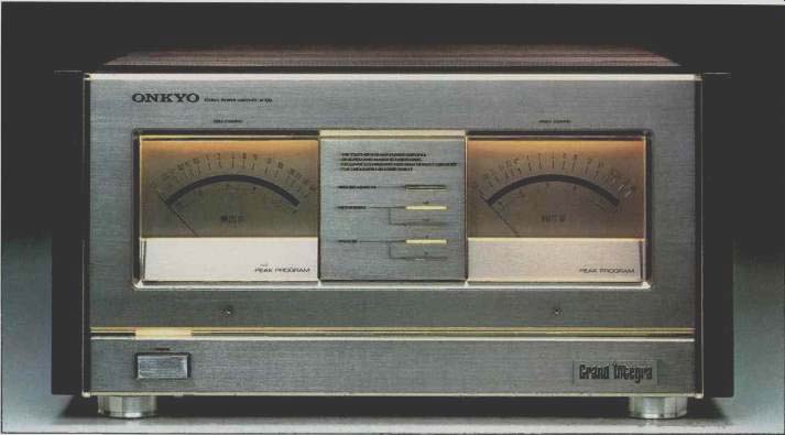
The ONKYO Grand Integra M-510 Power Amplifier combines transparency, musicality, and accurate spatial imaging together with sufficient power to drive any high quality loud speaker system, regardless of efficiency or load impedance.
Conservatively rated at 300 watts per channel, the M-510 features Onkyo's unique Real Phase power supply design, which prevents sonic degradation due to amplifier/speaker interaction.
Loudspeakers represent complex electrical loads, compared to the rather simple resistive loads used by engineers who design power amplifiers. Recently, many designers have examined the loudspeaker's impedance characteristics, and quality amplifiers now feature the ability to provide increased power output into lower impedance loads. This low impedance drive capability is necessary due to the changing impedance of a real loudspeaker, as well as to properly drive the growing number of low impedance rated speaker systems.
However, these designs still fail to take into account the reactive nature of the speaker load. The ONKYO Grand Integra M-510 Power Amplifier combines for the first time the Real Phase power supply design, with Onkyo's True Low Impedance Drive Capability.
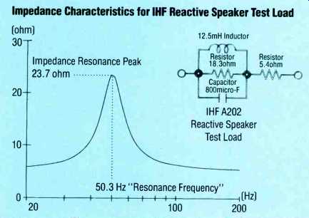
--------Impedance Characteristics for IHF Reactive Speaker Test Load--Loudspeakers
present complex, reactive loads to the amplifier. This is the impedance curve
from a loudspeaker load test model, showing a peak of 23.7 ohms at the 50.3
Hz resonance peak.
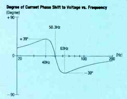
--------The graph shows the amount of phase shift between current and voltage
relative to frequency, with a phase shift of + 39 degrees below the resonance
point and-39 degrees above the resonance point.
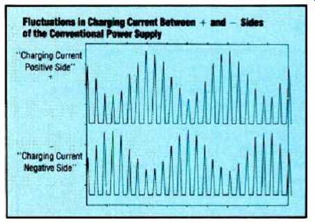
---- Fluctuations in the power supply charging cur rent between the '+'
and '-' sides of a conventional supply; these fluctuations cause a loss of
image specificity, "smearing" the stereo image.
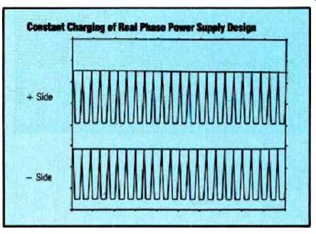
----The ONKYO Real Phase power supply design eliminates these fluctuations,
providing stable power on demand, resulting in precise stereo imaging, with
no loss of detail even during the most dynamic passages.
Power Supply:
The M-510 features three separate power supply systems. Essentially, the amplifier is a Dual Mono type; that is, the left and right channels are separate all the way back to the power switch and AC cord. Each of the two main power supplies features two power transformers; one, a large toroidal unit, features tremendous power handling capacity; the second, a Real Phase transformer about half the size of the main unit, smooths out fluctuations in charging current due to amplifier/speaker interaction. AC from the transformers is converted to DC by high current rectifiers, and each channel features two massive 33,000 micro-Farad 100 Volt filter/ storage capacitors.
Input Controls:
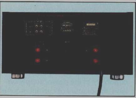
Two sets of inputs are provided on the rear panel. The set labeled "Direct" bypasses the front panel attenuators. The other set of inputs allow attenuation via the two precision potentiometers hidden behind the flip down front panel door. Both sets of inputs are direct coupled.
ONKYO's exclusive Super Servo circuit cancels DC and extremely low frequency AC (below 3 Hz) without the use of coupling capacitors.
Meters and Relays:
The third power supply system provides separate DC energy for the front panel lights, the protection circuitry, and the speaker relays. This ensures that large peak outputs can not affect these important sages in any way. Two sets of speakers can be hooked up to the M-510, and the switchable relays allow System A, System B, or System A + B operation.
The four output relays wired in parallel per channel provide extremely high current handling capability, with very low contact resistance so that damping remains high.
The front panel meters are peak reading, with fast attack and slow decay for maximum effectiveness. Each meter draws from a separate power supply, so the activities of one channel cannot affect the meter indication of the other. The meters are calibrated using 8 ohm loads, and are very accurate. Meter sensitivity can be changed from normal to-10db by a pushbutton; in the -10db mode full scale (0db) deflection indicates 30 watts into 8 ohms load. Approximate power output into 4 ohm loads can be calculated by doubling the meter readings. Approximate power output into 2 ohm loads can be calculated by quadrupling the meter readings.
Protection Systems:
The amplifier must protect both itself and the loudspeaker systems from damage in the event of component failure and/or severe overdrive conditions, but these systems must not interfere with musical integrity under normal conditions. Short term power available from the M-510, depending upon load impedance, can be over 2.5 kilowatts per channel, which can cause severe thermal damage to even the most rugged loudspeaker system.
The M-510 protection circuits will disrupt operation in the presence of the following conditions:
1. Overheated output stage(s)
2. Excessive DC at the input terminals
3. Amplifier output stage component failure reproducing DC
4. Excessive current flow at the speaker terminals in the presence of extremely low impedance loads at full power, including short circuit.
The protection circuits monitor the various conditions, but are totally isolated from the audio circuits by photoelectric opto-couplers. The protection systems are powered by the third main power supply and are thereby unaffected by high power consumption during peak audio signal conditions.
Start-up Sequence:
The start up sequence of the amplifier’s various stages is carefully controlled, in order to prevent excessive inrush current from the house AC line. Due to the massive storage capability of the power supply systems, the amount of current required during turn on of all three supplies at the same time would trip the house AC circuit breaker(s) or blow the fuse. Also, excessive turn on currents can damage circuit components, so the M-510 switches on in a gradual, con trolled manner.
Start up of the M-510 energizes the three power supplies in sequence, and after the DC storage is stabilized, the four audio stages are energized in sequence. Meter lighting is gradually increased to normal or low intensity, depending on the lighting switch selector, and after all stages are settled, the output relays close. The process takes about ten seconds. The front panel "Waiting Monitor" indicates the sequential turn-on of the four stages.
Pre-conditioning:
The input and driver stages of the M-510 amplifier are biased in true Class A constant current fashion. The output stage consists of fourteen high current transistors per channel, with a dissipation capability of 2 800 watts continuous. The output transistors are biased partially on all the time ( Class AB) using Onkyo's exclusive Linear Switching system to eliminate switching distortion. When the amplifier is first turned on, a special pre-heat system increases the output stage bias, until the correct output stage temperatures are reached. The front panel "Waiting Monitor" indicates correct output stage temperatures when all the LED's are lit. The amplifier will operate from approximately ten seconds after initial turn-on; however, distortion is higher when the output stage is cool, so we recommend the unit remain idle until the Waiting Monitor indicates correct output stage temperature. Idle current from the AC line is approximately 250 watts when cold, settling down to about160 watts when correct out put stage temperatures are reached.
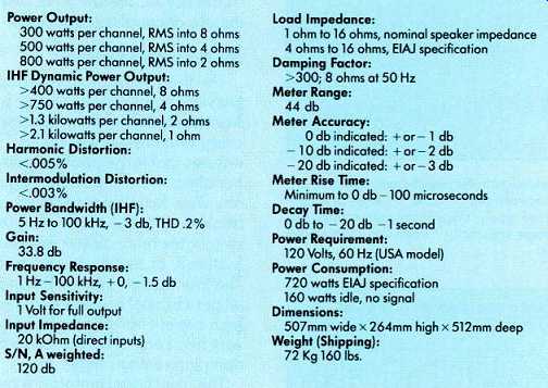
----PERFORMANCE SPECIFICATIONS
(Audio magazine, Jun. 1986)
Also see:
Onkyo--Artistry in Sound (ad, Apr. 1991)
Onkyo Acculinear 18-bit CD player (ad, Nov. 1988)
Onkyo DX-300 Compact Disc Player (ad, Sept. 1984)
Onkyo Audio System (Dec. 1972)
= = = =