Rockford Fosgate RF200 Preamp
Manufacturer's Specifications:
Frequency Response: Phono and high level, 20 Hz to 20 kHz, ±0.4 dB.
Maximum Output: 9.25 V rms.
Rated T HD: 0.005%.
Input Sensitivity: MM phono, 0.6 mV; high level, 60 mV.
Phono Overload: 75 mV at 1 kHz.
Maximum Input Signal: High level, 7.4 V rms.
S/N Ratio: Phono, 83 dB; high level, 90 dB.
Tone Control Range: Bass, ± 13 dB at 38 Hz; treble, ± 11 dB at 20 kHz.
Crossover: 12 dB per octave; supplied as -3 dB at 100 Hz for both high and low cut, modules available for other frequencies.
Crosstalk: Phono, -78 dB; high level, -90 dB.
Separation: Phono, 72 dB; high level, 76 dB.
Input Impedance: Phono, 47 kilohms in parallel with 150-pF capacitance; high level, 19.5 kilohms.
Dimensions: 17 1/2 in. W x 2 3/4 in. H x 8 1/4 in. D (44.5 cm x 7 cm x 20.6 cm).
Weight: 5.9 lbs. (2.7 kg).
Price: $575.
Company Address: 613 South Rockford Dr., Tempe, Ariz. 85281, USA.
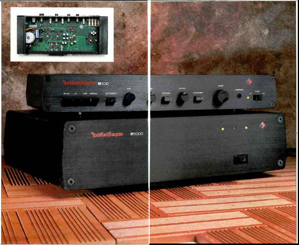
The Rockford Fosgate RF200 is a fitting companion for the RF2000 power amplifier, also tested for this issue. It is designed to be placed on a shelf, although a rack-mount front panel is optional. The RF200 has an external processing loop in addition to the usual tape monitor loop. There are also dual sets of preamp outputs so that several power amplifiers can be connected. An unusual feature is this preamp's set of active adjustable crossovers, which can be adjusted by exchanging modules (eight-pin DIP packages) accessible from the back panel.
The unit's power supply, like that of the matching RF2000 amp, employs a toroidally wound transformer. Its smaller size, higher efficiency, and freedom from stray magnetic fields make it an ideal choice for a preamplifier of this high quality. There are few frills on the RF200, which is perhaps indicative of the fact that Rockford has chosen to stress performance and sound quality rather than needless switches and knobs.
Control Layout
On the left of the preamp's front panel are four pushbutton selectors for choosing "Phono," "CD," "Tuner," or "Video/ AUX" inputs. Nearby but separated from these others is a "Tape Monitor" pushbutton. "Bass" and "Treble" tone control knobs come next, together with a separate "Tone By pass" switch. Between the rotary "Balance" and "Volume" knobs is a "Mono/Stereo" switch. A 'phone jack, power indicator light, and on/off power switch complete the front-panel layout.
The rear panel is equipped with the required pairs of input jacks. Phono jacks accommodate only moving-magnet cartridges, so if you want to use a moving-coil pickup, you will need either a suitable step-up transformer or a separate pre-preamplifier. Tape loop record-out and tape-in jack pairs are also found on the rear panel, as are the jacks for the external processor loop. These are shipped with jumper bars installed, but if the bars are removed, external processors, such as a graphic or parametric equalizer or a dynamic range expander, can be connected to the system.
In addition to the pair of "Main Out" jacks, outputs la belled "High Out" and "Low Out" are provided in case you plan to configure a biamplified system. As an option, you can press a button behind the crossover's cover to bypass the "High Out" crossover network. Doing so will cause the signal at the "High Out" jacks to be the same as that at the "Main Out" jacks. The RF200 is capable of simultaneously feeding all three sets of outputs--main, low, and high. A switched a.c. outlet and a ground terminal are also on the rear panel, as is a crossover module access cover. Removing this cover reveals the frequency module used to create the crossover filters. Other frequency modules are avail able, but if the specific crossover frequencies you want are not available, the owner's manual offers advice on how to build your own, complete with a table of resistor values for some 18 different crossover frequencies.
Measurements
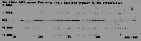
Fig. 1--Frequency response via high-level inputs.
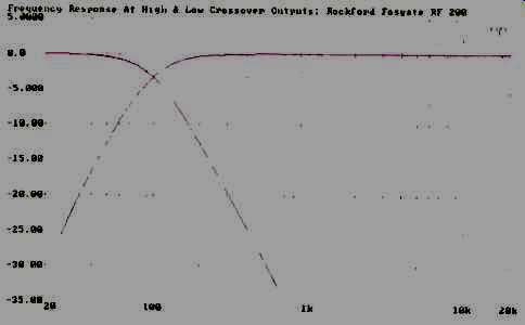
Fig. 2--Response of built in crossover, set for 100 Hz, measured at
high and low outputs.
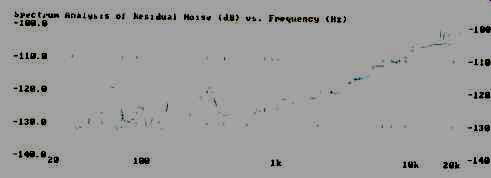
Fig. 3--Spectrum analysis of residual noise (in dB, re: 0.5 V), with
high-level input selected and volume set for unity gain.
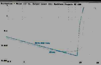
Fig. 4-THD + N vs output level.
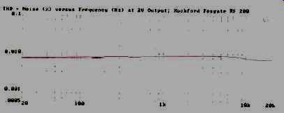
Fig. 5-THD+ N vs. frequency, at 2 V out.
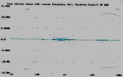
Fig. 6--Tone control range.
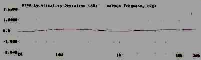
Fig. 7--RIAA equalization error, using MM input.
High-level frequency response was virtually flat from 10 Hz to 200 kHz, as shown in Fig. 1. I also measured frequency response at the "High Out" and "Low Out" jacks and superimposed the curves in Fig. 2. As you can see, the crossover frequency, as supplied by Rockford, was almost precisely at 100 Hz, and attenuation was exactly -3 dB at that point. High-level, A-weighted S/N ratio measured 88.1 dB for the left channel and 86.8 dB for the right. These results were obtained using an input level of 0.5 V and adjusting the volume control to produce unity gain, or an output of 0.5 V.
Figure 3 is a spectrum analysis of residual noise versus frequency, referred to the same input and output levels.
Note the minimal contribution of the power-line frequency (60 Hz) and its harmonics and the similarity of the noise spectra of each channel. These plots reveal the advantages of using a toroidal power transformer and show its ability to contain any magnetic fields generated in the power supply.
Figure 4 shows how THD + N varied with increasing output levels, for 20-Hz, 1-kHz, and 20-kHz signals. It is important to understand that, while the percentages of THD + N seem higher for lower output levels, these tests include the sum of distortion plus noise. At lower levels, the residual noise adds to the overall percentage read by the test equipment; at higher levels, however, what you see is dominated by the distortion itself. At 5 V output, for example, the total THD + N at all three test frequencies was only about 0.004%. Figure 5 shows that THD + N remained virtually constant at around 0.007%, decreasing slightly at the extreme treble frequencies, when output was regulated by the test equipment to remain constant at 2.0 V. Again, these results represent the sum of THD + N. Had I been able to separate distortion from noise, I have no doubt that the figure would have been well below the 0.005% claimed.
The range of the bass and treble tone controls is shown in the multiple sweeps of Fig. 6. Of particular significance is the fact that, even at maximum boost or cut settings of both controls, very little alteration of mid-frequency response occurs. If a preamp is going to be limited to bass and treble tone controls, I've always maintained that this is the way they should be designed. All too often, controls of this type have a very significant effect upon the important midrange frequencies, which, I feel, makes them virtually useless in compensating for problems of room acoustics or in allowing some tweaking at the frequency extremes on certain pro gram material.
High-level input sensitivity measured 55 mV for an output of 0.5 V. Overall maximum gain of the high-level circuitry was, therefore, 19.2 dB. Maximum output for the high-level inputs was 8.2 V.
Input sensitivity for the phono section was 0.5 mV for 0.5 V out, so overall gain from phono input to output was exactly 60 dB. A-weighted S/N ratio for the phono inputs was 76.9 dB for the left channel and 72.7 dB for the right. These figures are referred to 5 mV input, with volume adjusted to provide 0.5 V output. Phono overload occurred with an input signal of 77 mV at 1 kHz.
This preamp's RIAA equalization was one of the most accurate I have ever measured. Figure 7 shows deviation from perfect RIAA playback equalization, with the tone controls set flat (or defeated). There was never more than 0.2 dB of equalization error, and that maximum occurred way out at 20 kHz.
Conclusion
As Rockford states in the owner's manual, they set out to design and build a reliable preamplifier devoid of needless frills and capable of delivering accurate, distortion-free signals to a power amplifier. In this they have succeeded eminently well. Everything about this preamplifier connotes quality and care--from the nicely crafted knobs used for tone, balance, and volume control to the high-quality internal parts on the well laid-out circuit board. As for the RF200's sound quality, I will discuss that in my companion report on the Rockford Fosgate RF2000 amplifier. These two components together, though not inexpensive, could certainly be the foundation for an audio component system anyone could happily live with.
-Leonard Feldman
ROCKFORD FOSGATE RF2000 POWER AMP
Manufacturer's Specifications:
Power Output: 200 watts per channel into 8-ohm loads, 20 Hz to 20 kHz; 300 watts per channel into 4-ohm loads, 20 Hz to 20 kHz; bridged mode, 600 watts into 8-ohm load.
Rated THD: 0.05% with 8-ohm loads, 0.1% with 4-ohm loads.
Rated IM Distortion: 0.01 % with 8-ohm loads, 0.02% with 4-ohm loads.
Slew Rate: 80 V/uS.
Frequency Response: 20 Hz to 20 +0.1, -0.25 dB; 5 Hz to 75 +0.1, -3.0 dB.
S/N Ratio: 110 dB, re: full power.
Peak Output Current: 50 amperes.
Dimensions: 17 1/2 in. W x 4 1/2 in. H x 13 in. D (44.5 cm x 11.4 cm x cm).
Weight: 35 lbs. (15.9 kg).
Price: $1,250.
Company Address: 613 South Rockford Dr., Tempe, Ariz. 85281, USA.
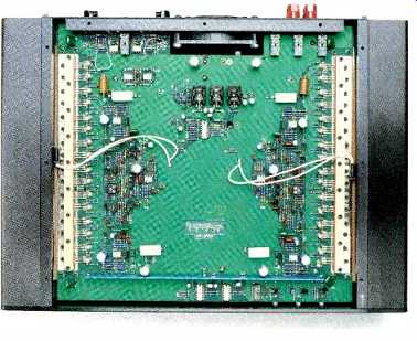
The RF2000 power amplifier is the first in a series of high-performance audio components offered by Rockford Fosgate, an Arizona-based manufacturer which has gained a good reputation in the professional audio field.
In fact, in most details, the RF2000 is similar to the company's PRF2000 professional model. The chief differences lie in the input arrangement: The pro version permits balanced or unbalanced operation and uses XLR or phono-jack input terminals, whereas the version I tested has standard RCA photo jacks.
Tie RF2000 uses a total of 32 MOS-FET output devices, 16 per channel. Each device is rated at 4.0 amperes continuous current drain at a tempera ture of 100° C. The amp is fully rated for loads of 8 and 4 ohms and is stable down to load impedances of 2 ohms. A form of analog computing system protect; the output devices: Device temperature is continuously calculated and compared to a maximum limit; if the limit is reached, the power is automatically cut back and the front-panel LED for the affected channel turns red.
A pair of thermistors, one on each heat-sink, measures temperature of the input system. The thermistors control fan speed and provide thermal shutdown when temperatures are too high for safe operation. The cooling fan has continuously variable speed control and is extremely quiet. As the amp is driven harder, the fan turns on and gradually speeds up to whatever extent will allow the power dissipation needed for the operating conditions.
The amp's power supply uses a 1,000-VA toroidal transformer. Energy storage for the supply consists of two 42,000 uF capacitors. This large capacity provides a low impedance source of high current to handle surges, musical transients, and wide variations in speaker impedance.
Four output modes of operation are available. The RF2000 can, of course, be operated as a two-channel stereo amplifier or, in bridged mode, as a single-channel amp for higher power requirements. In addition, the amplifier can be operated in dual mono, with both channels driven by the same input signal. You might, for example, use this configuration to bi-amplify a speaker which has separate inputs for the high- and low-pass sections of its internal crossover network. Or you might want to drive multiple speakers whose parallel impedance would be too low if driven from the amplifier in its single-channel bridged mode.
Finally, this amp can be operated in stereo-plus-bridged mode, which allows you to drive a pair of satellite speakers and a bridged mono subwoofer or bridged center channel speaker simultaneously, using only a single RF2000 amplifier. This is the first home stereo amplifier I've encountered that offers this last configuration, which I suspect will be welcomed by many owners of three-piece satellite/subwoofer systems.
Control Layout
A three-LED multicolor display on the unit's front panel shows amplifier status, including power, signal level, distortion, and thermal condition. The channel status LEDs remain off when there is no signal or when output levels are below about 200 mW; they turn green when output power exceeds this figure-so long as the amplifier's distortion remains low-and turn red when the output signal becomes distort ed. The power status LED also has three indications, being off when the RF2000 is shut off, green in normal operation, and red when the amplifier's overheat-protection system is activated.
On the right of the rear panel are the left and right input jacks, each accompanied by its own gain control. Gain can be varied from 0 to 36 dB by means of these controls. The fan grille is at the center of the rear panel; to its left are color coded, five-way speaker terminals and individual 5-ampere fuse-holders. The fuses are for speaker protection only; during my tests, I found it necessary to replace them with fuses of higher amperage in order to conduct tests of rated power output.
Pushbutton switches are provided for setting any of the operating modes previously described, so that it is not necessary to alter any internal wiring to achieve bridged mono, dual mono, stereo, or stereo plus bridged mono operation. Another pushbutton switch selects either "Floating" ground (chassis and output sections grounded separately) or "Chassis" ground (chassis and output grounded together).
Measurements
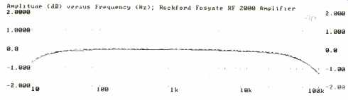
Fig. 1--Frequency response.
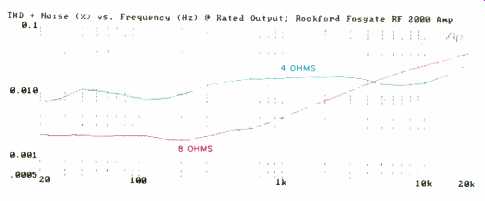
Fig. 2--THD + N vs. frequency, at rated power output of 200 watts per
channel into 8 ohms and 300 watts per channel into 4 ohms.
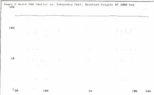
Fig. 3--Power output for rated distortion of 0.05% into 8 ohms.
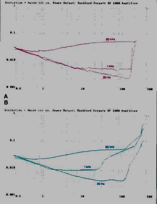
Fig. 4--THD + N vs. power output per channel into 8 ohms (A) and 4 ohms
(B). The distortion at high power output levels for 4-ohm loads is due
to limitations of test setup; see text.
Figure 1 is a plot of frequency response over the range from 10 Hz to 100 kHz. At 20 Hz, response was down about 0.2 dB, while at 20 kHz, it was off by a mere 0.14 dB. At 100 kHz, response was off by only 1.25 dB.
Figure 2 shows how THD + N varied with frequency for both 8- and 4-ohm loads. With input signals carefully regulated by my test system to maintain a constant output of 200 watts per channel into 8 ohms, I measured only around 0.002% below 200 Hz, 0.0041% at 1 kHz, and 0.043% at 20 kHz-all well within the manufacturer's published claims.
For 4-ohm loads, with output regulated to a constant 300 watts per channel, THD + N was only 0.0065% at 20 Hz, rising to an insignificant 0.018% at 1 kHz and to 0.03% at 20 kHz-all far lower than the 0.1% specified by Rockford.
I was curious to see just how much power the amplifier could produce for its rated THD, so I tried a new test:
Plotting power output for rated distortion--in this case, 0.05% for 8 ohms. The results are shown in Fig. 3. I was amazed to find that this rugged amplifier was able to deliver around 250 watts per channel, with both channels driven into 8-ohm loads, over almost the entire audio spectrum.
Figures 4A and 4B show how THD + N varied as a function of power output for three test frequencies-20 Hz, 1 kHz, and 20 kHz-with 8- and 4-ohm loads. In making the 4 ohm measurement (Fig. 4B), I noted that THD + N at the rated power level of 300 watts per channel exceeded the manufacturer's 0.1% rating. I was puzzled by this, until I discovered that the regulation of my variable-voltage trans former--used to maintain a steady 120 V a.c. for powering amps during these tests--was not as good as I had thought it was. As the sweeps of Figs. 4A and 4B progressed from low power levels (0.2 watt per channel or less) to higher power levels, I noted that the line voltage began to dip below the 120 mark at the end of each sweep. The lesson is, if you want to get full power out of any power amplifier, you'd better make sure your line voltage is really at 120 V! Figure 5 shows low SMPTE-IM distortion varied with power output. With 8-dhm loads, SMPTE IM measured only 0.0066% at an output of 200 watts per channel; with 4-ohm loads, it was 0.03% at an output of 300 watts per channel.
Once again, the poor regulation of my variable-voltage transformer caused the line voltage to dip slightly below 120 V at the high end of this sweep, which accounts for the SMPTE-IM figure being slightly higher than specified for 4-ohm loads. I confirmed that this was so by taking a fixed, or spot, reading of SMPTE IM, manually adjusting the line voltage to precisely 120 V. Now, for an output of 300 watts per channel with 4-ohm loads, SMPTE IM was indeed well below 0.02%, measuring only 0.015%. I also conducted a test of CCIF-IM (twin-tone) distortion as a function of power output, using 18- and 19-kHz test signals mixed in equal proportions (Fig. 6). For 8-ohm loads, CCIF IM was only 0.002% at an output of 200 watts per channel; for 4-ohm loads, CCIF IM was 0.025% at an output of 300 watts per channel.
A-weighted S/N ratio measured 89.9 dB for the left channel and 86.3 dB for the right channel. These measurements were made with respect to 1 watt output. Translated to a reference of full output (200 watts into 8-ohm loads), this would work out to be 112.9 dB for the left channel and 109.3 dB for the right channel.
With 8-ohm loads, the RF2000 exhibited an extremely high dynamic headroom of 2.44 dB. So, for short bursts, the amp can be expected to deliver peaks up to 350 watts per channel! Damping factor, also referred to 8-ohm loads and using a test signal of 50 Hz, measured 210.
Input sensitivity was approximately 640 mV for rated output, with gain controls fully open. In terms of EIA standards, it would therefore take approximately 45 mV to produce 1 watt output into 8-ohm loads.
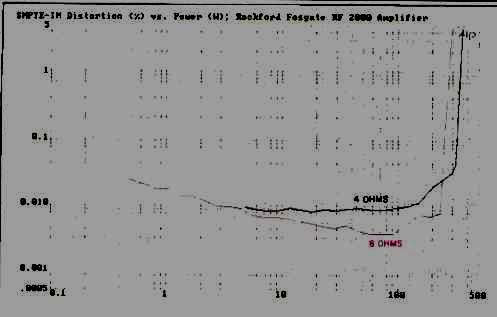
Fig. 5--SMPTE-IM distortion vs. power output into 8- and 4-ohm loads.
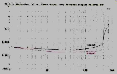
Fig. 6--CCIF-IM (twin-tone) distortion vs. power output into 8- and
4-ohm loads.
Use and Listening Tests
The attributes of the RF2000 can be summed up in a couple of sentences. It is a remarkably stable and reliable amplifier that seemed impervious to any failure-no matter how hard I drove it. Of course, I popped some speaker fuses during my tests, but not once did the amp shut down because of thermal problems or for any other reason. I can assure you that my bench tests subjected this amp to far more stressful conditions than it is likely to encounter under normal use as a music signal amplifier in a home system.
Since I tested the Rockford Fosgate RF2000 power amplifier and the RF200 preamplifier during the same couple of weeks, it seemed appropriate to do my listening tests with both units in the setup. The power amp was used to drive KEF 105/2 reference loudspeakers with a Sony CDP 650ESD reference CD player as a source. In addition, a DAT recorder I acquired overseas is not incorporated in my listening setup, so I played one of the few prerecorded DATs I own. It is a Classic Masters recording of Mozart piano sonatas played by Richard Shirk (CMDT-1005); the same program material is also available on CD (CMCD 1005). Among the newer CDs I used to confirm the sound quality of these components were two Telarc releases. The Young Bach (CD-80179) features Michael Murray playing the organ at the College of St. Thomas in St. Paul, Minn. The power and majesty of that organ sound was beautifully reproduced by this pair of components, which showed no sign of strain or overload--even during the deep bass passages. The second disc (CD-80186) presents four of Mozart's lesser known symphonies--Nos. 24, 26, 27, and 30--and was recorded with Sir Charles Mackerras and the Prague Chamber Orchestra. This disc illustrates how a relatively small instrumental ensemble can create a well balanced sound on CD that, with the aid of good equipment such as this Rockford Fosgate pair, can transport the listener into an imaginary concert hall of the appropriately small dimensions suited to this music. Oh, yes--I subjected the combination to more contemporary works as well-including some New Wave music. No matter what I fed these top performing components, they seemed equal to the task, and then some. Interestingly, although I sought material with extremes of dynamic range, I was never bothered by the fan in the RF2000 amplifier. Either it wasn't running at all or it was running at such slow speeds and so quietly that it did not serve as a noise-floor limit to my extended listening. I had thought the RF2000's $1,250 price tag was a bit high.
Happily, the $575 price for the RF200 preamp is, if anything, on the low side, considering its performance. So, in my opinion, the total cost for these two components comes in just about where it belongs.
-Leonard Feldman
(Audio magazine, Jun. 1990)
Also see:
SAE Mk IIICM Basic Amplifier (Jan. 1975)
Robertson Sixty Ten Amplifier (Jan. 1986)
= = = =