Input Impedance and Volume Setting
Q. I have seen it stated that a power amplifier's input impedance is "independent of level pot at input." How can this be?
-M. Notkins, New York, N.Y.
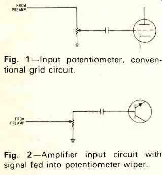
A. You know that tube amplifiers have high impedance inputs. The impedance at the grid of an input circuit is high enough so that, even when the slider of pot to which it is connected was moved to its highest setting, this grid circuit will not appreciably load down the preamplifier's output circuit.
See Fig. 1.
If a pot is wired in the same as a tube circuit, but using transistors, and if the impedance of the input transistor is very high, as compared to the, resistance of the input pot, any change in loading will not significantly change the loading on the preamplifier's output. Of course, if you inject the input signal at the wiper of the pot, and if the pot is completely counterclockwise, the input impedance will be zero ohms because the pot presents a short to ground. See Fig. 2.
Any amplifier designed in this manner cannot meet the statement in your question. The input impedance varies between a maximum and zero ohms.

Fig. 1-Input potentiometer, conventional grid circuit.
Fig. 2-Amplifier input circuit with signal fed into potentiometer wiper.
Four-Channel Sound
Q. In a two-channel system of tape deck, turntable, four 80-watt speakers, and a 240-watt receiver, can a four channel amplifier be satisfactorily integrated to produce four-channel sound effect? If so, what size (in watts) is recommended?
-Sp/4 James C. Gunter.
A. […] two-channel …. is to obtain an integrated two-channel amplifier. If it is of the same basic design as your receiver, so much the better because phase relationships will be preserved. You will not need as much power to drive the rear channels, at least for classical music listening.
This may even be true of some "pop" material.
Where you are using four separate channels from tape right on out through speakers, however, I suggest that you have the same amount of amplifier power feeding the rear channels as feeds the front ones so that in the event there is primary information on any of the channels, including the rear, it can be recovered as it should be heard. In your case, therefore, each rear channel should be capable of 120 watts of amplifier power, for a total of 240 watts--equaling the power available from the front two amplifier channels. Where your speakers are very efficient or where you do not plan to do loud listening, you can settle for considerably less power in both the front and rear channels. In the event you already have your amplifier for the two front channels, you can, given the above conditions use less power in the rear channels. However, it seems to me that you might have some problems with phase relationships when using an amplifier whose design is different from that which you are using for the front channels.
The loudspeakers should have sufficient power so as to be capable of all the power you plan to deliver to them. How much power that actually represents will depend on such factors as your listening level preference and room acoustics. Speaker efficiency, too, can play a role.
Capacitor Life Span
Q. Do mylar tubular capacitors and ceramics deteriorate with age? If so, is the deterioration gradual or is there usually a sudden failure? If gradual, what is the effect upon power amplifier performance? Is there an average life span for these components, beyond which replacement is advisable? Similar advice re electrolytic capacitors will be appreciated.
-Walter Diehl, Great Neck, N.Y.
A. Tubular paper capacitors and ceramic units do not usually fail; their life span is indefinite. When they do fail, however, they will fail suddenly and completely. They will either completely short or they will open.
Electrolytics will fail after a time. I do not know if we can specify a definite life span for them, but perhaps ten years is about what can be expected of most of them. Some will last longer and others a shorter length of time. Electrolytic capacitors fail gradually, losing their capacitance little by little, Depending upon their location in a circuit this gradual decrease in capacitance can lead to loss of bass response, crosstalk between channels, leakage of signal even with the gain control turned down fully, motor boating, and hum.
As is true of paper and ceramic capacitors, electrolytics are also subject to catastrophic failure. Sometimes, too, the internal connections between the lugs and the foil can become defective, leading to intermittent operation of the capacitor.
If you have electrolytic capacitors in the "junk box," you may find that they deteriorated in another respect. Their breakdown voltage may become lower than their nominal rating. If you plan to use a capacitor which has been stored for long periods, you can take precautions to see that it does not fail when placed in service. You can reform the electrolytic coating. This requires the use of a variable voltage power supply. Connect the capacitor in series with a resistor whose value is in the order of 50K or 100K ohms, ten watts. Connect this series combination across the power supply, being careful of polarity. If the capacitor is rated at 450 V, start with approximately 200 volts. Over a period of several hours, gradually bring up the voltage to the rated value. You should allow at least 12 hours for this operation.
It is possible that the capacitor will short out during this reforming process. Of course, it must then be discarded. The resistor, therefore, is used to limit the current flowing in the circuit, thereby protecting the power supply from possible damage.
(Audio magazine, Jul. 1972, Joseph Giovanelli)
= = = =