Discrete vs. SQ Matrix Quadraphonic Disc
An address before the 1972 Midwest Acoustics Conference April 15, 1972.
By Benjamin B. Bauer
THE PRESENT-DAY MULTIPLICITY Of contradictory proposals and extraordinary efforts by many people directed to the problem of offering four-channel sound on a disc record reminds me of the legend of three friends lost in a jungle. Said one, "This calls for the direct approach: Let us clear a path with our machetes which will lead us out of this jungle." So they hacked furiously ahead for several hours and finally gave up exhausted. Then the second said, "Let's sit down and wait; `they' surely will send a search party after us, and eventually they will find us." After several days of waiting, the three friends were starved and drenched and in a desperate mood. Then, the third one had an idea; he climbed the tallest tree, got an overview of the jungle, and at once saw the route that would lead them out.
Since I have the privilege of being the first speaker at this symposium, it is appropriate that I try to take such an overview; and I can do this best by reviewing just two of the several quadraphonic disc projects we have conducted at CBS Laboratories during the past years, one of the "discrete" or "carrier" variety and the other involving "matrices." Out of this review I trust you will understand our reasons for adopting the SQ matrix record system, rather than continuing to hack straight ahead with a carrier approach or to just sit and wait for someone else to solve the problem. And, I also hope that our experiences with carrier systems may prove valuable to those who are still working on this alternate route.
But first, let me engage in a brief philosophical observation: Modern science opens up numerous options to the engineer--a heady potion if not taken with thoughtful moderation. It is easy to become lured by technological sophistications and lose sight of the need to develop products that truly serve the larger public interest. Since we are meeting in the Chicago can't help but remember the admonition of Paul … a convocation of the Institute of Radio Engineers, right here, over three decades ago: What he said was "you engineers should remember to serve not your own vanity, but the needs of the public." And, with this motto, he proceeded to build a great industrial enterprise. Today this motto is more applicable than ever. Let me paraphrase it and apply it to the quadraphonic disc record by reminding all of us that our ultimate objective in this area should be to provide an excellent quadraphonic experience to millions of listeners utilizing, rather than outmoding, the investment they have made in record players and FM multiplex receivers, and not merely demonstrating the technical feasibility of a quadraphonic approach that will be available to but a few. The four channel market will not be significant for the artist, the hardware manufacturer, the broadcaster, or for the record company unless, through an appropriately designed disc medium selected to serve as a solid foundation for future progress, it can also become a mass market for all to enjoy.
Compatibility
All of this brings us to consideration of compatibility. The owners of record players simply have too great an investment in equipment and records to allow us to disregard their interests. Thus, early in the game we decided that we had to insist that our quadraphonic records be fully compatible with current equipment. This concept of compatibility has many dimensions.
For example, we decided that our compatible record should not just produce pleasing sound on existing mono and stereo phonographs, but also that it would have to perform flawlessly thereon. And this high quality of performance would have to extend to all operating characteristics including: recording time and level; signal-to-noise ratio; frequency response and stereophonic space perspective. All these must be equal or superior to those produced by the existing stereophonic records.
And, to be truly compatible, it should be suitable for transmitting quadraphonically over existing FM/multiplex systems, as well as in the monophonic mode over existing AM radio systems.
With the above requirements in mind, we can now take an overview of carrier and matrix quadraphonic record technology.
Carrier-Type Quadraphonic Record Technology
Fig. 1-Matrixing arrangement, experimental SSB quadraphonic disc system.
The direct approach for placing four independent audio signals on a two-channel medium is by time-division multiplexing or by using carrier methods. When we began our carrier efforts we were aware of the potential capabilities and pitfalls of this approach, having had an occasion about a decade earlier to master a stereophonic test record, the STR 120, which spanned the frequency range of 10 Hz to 50,000 Hz.
(The STR 120 is currently unavailable for sale since all the metal parts for stamping this record have been exhausted.) Since even the most advanced disc cutters do not operate efficiently above 20 kHz, it is necessary to slow down the recording turntables in order to scale down the frequencies; which in turn creates trouble at the bass end, and requires the use of specially lapped styli with miniscule burnishing facets for the shortened wavelengths, which tend to produce a noisier lacquer than conventional styli and to fracture unexpectedly in the middle of a cut. Nevertheless, despite this prior information, it was our contention that carrier methods should not go unexplored and thus our initial work on quadraphonic disc systems at CBS Laboratories was based on the use of carriers.
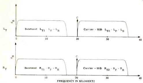
As shown in Fig. 1 each disc channel was provided with a baseband of 20-15,000 Hz, and to this we added a 20 kHz carrier, single-sideband modulated (SSB) from 20,000 to 35,000 Hz. In this manner four independent channels, LT1 and RT1 on the baseband and LT2 and RT2 on the carriers, each with a capacity of 20-15,000 Hz, were obtained. On these we recorded a linear combination or "matrix" of four input signals, LF (Left-Front), RF (Right-Front), LB (Left-Back) and RB (Right Back), in the following manner:
Upon replay and detection, we recover the four left-hand side signals of Equations 1-4.
The original four signals can now be obtained as follows:
It should be noted that this "discrete" disc is not naturally discrete but is responsive to a matrix action: "Discreteness" is attempted by signal cancellation, which at no time is ideal.
Moreover, we found that the matrix according to Equations (1) and (2) presents an inadequate stereophonic portrayal of the quadraphonic field. Constant power distribution around the quadraphonic circuit results in a concentration of energy in the extreme position of the stereophonic field with diminished center fill, resulting in a ping-pong type presentation; motion between side channels, of course, is lost. Now we … matrixes are available for the baseband wing the SQ matrix later to be ….at this time, however, is that no matter what mixture 'of four original signals is employed with a system which has four independent channels, it is always possible to recover the original signals identically as long as the matrix equations are non-trivial and are linearly independent. If the solution is carried out by means of Cramer's rule', this means that the determinant of coefficients in Equations (1)-(4) must not vanish.
We were fully aware, of course, that a 15,000 Hz top end in the system depicted in Fig. 1 would not meet the needs of high-fidelity reproduction, but our view was that we should begin by working within this range and look for further improvement later if the approach proved out. We knew we were already stretching the limits of available technology and any greater demands upon the system simply would compound its difficulties. And the difficulties were many. In addition to the technical recording problems enumerated above, we knew in advance that a linearization process would be required for the baseband and the carrier signals, to minimize distortion. The record player required the use of costly filters to separate the basebands from the carriers, and two detectors were needed, followed by the de-matrixing circuit. Furthermore, previous experiments had alerted us to the fact that even with the costliest of pickups, high frequency response beyond 20 kHz would leave much to be desired.' This situation continues to be prevalent even today as exemplified by the graph in Fig. 2.
Fig. 2--Replay of stereophonic pickup on STR-120 record.
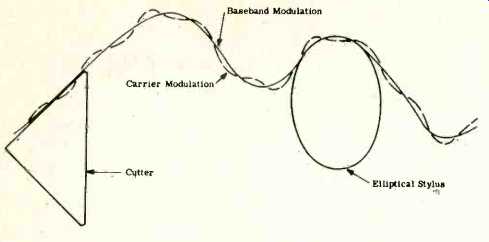
Fig. 3--Portrayal of recording and playback limitations, carrier-type
disc.
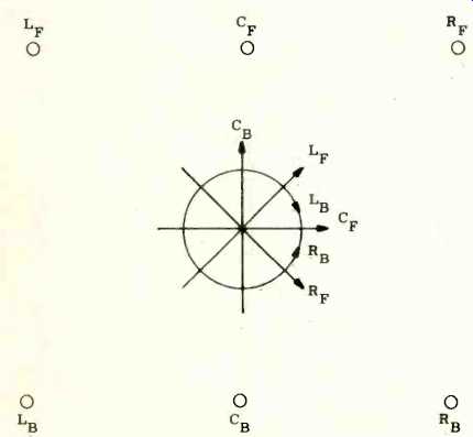
Fig. 4--Six principal modulations of the SQ matrix system.
This exhibit shows the performance of the best (from the point of view of high-frequency response) currently available phonograph pickup cartridge, with 0.7 x 0.25 mil diamond stylus, retailing for upward of $100, measured at 11 gram force on the 111 in. and 6-in. radius grooves of the STR-120 record. The curves show that, while response extends to approximately 35,000 Hz at the 11-in. diameter groove, it does not go much beyond 27,000 Hz at 6 in. Thus, one cannot count on being able to recover much beyond 7,000 Hz from the 20 kHz carrier channel toward the end of the disc, even if one does not record all the way into the center of the record. While the restricted frequency range of the pickup, in theory at least, can be improved with future refinements, other related problems do not appear to be amenable to conceptually simple solutions. Fig. 3 depicts the baseband modulation at high frequency as a solid curve produced by the cutter (triangle at left) and replayed with a 0.2 x 0.7-mil elliptical stylus (ellipse at right). The maximum modulation angle we encounter in records is 45°--(actually less than that on the negative modulation slopes because of the "smearing" action of the burnishing facet which gives rise to modulation noise). Let's superimpose a carrier shown in dash-line upon the base band. The lateral velocity of the carrier as defined by its slope is of the same order of magnitude as that of the baseband; its radius of curvature actually may be considerably smaller. Therefore, the aforementioned carrier takes up as much or more "modulation space" as the baseband itself. In order to cut the composite wave on the lacquer disc, the magnitude of the combination has to be diminished, say, by a factor of … or 6 dB. This is precisely what we had to do with our experimental carrier discs to obtain a quiet cut and to avoid excessive distortion. Even with the above-mentioned reduction in level, the pickup with elliptical stylus was unable to recover the ultrasonic signals at diameters below 6. in. This appears to be tied-in with the elasticity of the groove material which results in a high-frequency cutoff as predicted by Miller'. Thus, it became clear to us, as our experiments proceeded, that the carrier disc approaches would neither meet the compatibility requirements enumerated earlier, nor always fulfill their discrete promise because:
A) The signal level, frequency response, distortion, and signal-to-noise ratio were marginal.
B) The special pickup and complicated decoder were too costly to satisfy the needs of the mass market.
C) Playing time per side was inadequate for the repertoire.
D) FM multiplex quadraphonic transmission problem remained unsolved.
[…] problems were exacerbated by the vagaries … ultrasonic frequencies often resulting ….
Recent Carrier Disc Developments
Improvements and implementations of carrier disc technology have been reported last year by Inoue and his associates', and more recently by Shiga and Coopers. As we review (their findings, we conclude that even the advances they have reported do not substantially change our conclusions. To review briefly:
1. Inoue uses a 15 kHz baseband, as we did, but with a 30 kHz carrier which is FM-PM modulated over a swing of 20-45 kHz. Thus, his system like our early one, is limited to the 15 kHz capability. While it has been reported that pickups suitable for Inoue's method are now available for the top line of players, there is historical experience for doubting that hey will reach the mass market any time in the near future.
Unfortunately, the FM-PM modulation method is extremely sensitive to turntable speed; and any pickup response cutoff earlier than 40 kHz will cause a dis-symmetrical carrier recovery, generating distortion. Also, Inoue uses a compression expansion scheme to diminish carrier noise which further increases playback equipment complexity and cost, and raises added channel separation problems.
2. Shiga and Cooper, we understand, have simplified the carrier problem by adopting a lowered carrier frequency and modulation range to' achieve discrete or semi-discrete performance in the lower 3 kHz portion of the baseband, returning to pure matrix performance at frequencies above 3 kHz. While, on the one hand,' this results in a commendable simplification of the recording problem, on the other, it builds in an unalterable quality limitation in the system.
Thus, of the three carrier methods discussed above, we think the SSB approach we chose, with all its problems, in the end might have resulted in the best compromise. However, this is not the place to debate the specific sub-issues. The key point to be made here is that the optimum carrier system parameters have not as yet been evolved as witnessed by the diverse problems and solutions we have described, and the carrier disc technology will require considerably more time and effort before it can seriously be considered as a mass market product for the home. And, even if it were to be fully developed, it still will include certain limitations-such as incompatibility with stereo multiplex broadcasting-that will make its widespread adoption undesirable.
SQ Quadraphonic Matrix System
Knowing all the carrier-disc complexities discussed above, we concentrated' our efforts on pure matrix systems which resulted in the development Of the SQ matrix which, as it turns out, provides a viable method of quadraphonic recording and reproduction without the use of carriers.
The first important attribute, and the source of total stereophonic compatibility of the SQ matrix is that, for the front signals of a hexaphonic array of sound sources, it retains precisely the same modulation format as normally found in a stereophonic disc. The LF and RF signals form 45° and-45° modulations, respectively, as shown in Fig. 4, and the matrixed center-front channel (CF) forms a lateral modulation.
Our problem was how to provide the same capability for the back channel signals. Time and space do not permit reviewing all the possibilities we explored before coming up with the final solution. In the SQ system the cardinal back channels are inscribed with a circular motion of the cutter in such manner that the left-back (LB) modulation produces a clockwise helix and the right-back (RB) modulation produces a counterclockwise helix. The phases between' the helixes are arranged so that the center-back (CB) signal results in a vertical modulation.'
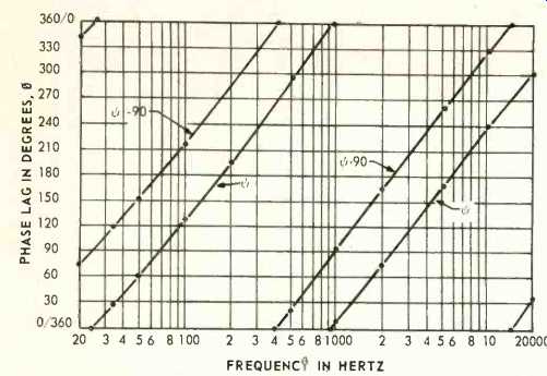
Fig. 5--Phase-shift functions used in SQ matrix encoding.
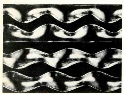
Fig. 6--Photomicrograph showing groove modulation of SQ record.
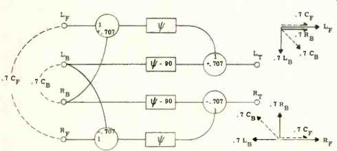
Fig. 7--Block diagram, SQ encoder.
The helical modulations are formed by the expedient of passing each back-channel signal through a pair of all-pass phase-shift networks ("psi-networks") producing a phase-quadrature relationship between the two signals at all frequencies. The functions used in the SQ record are shown in Fig. 5. In the frequency range of 20-20,000 Hz, the phase differential is held within 1° of arc and the transmission characteristics are maintained within 1/4 dB. A microphotograph…the four corner modulations is shown in Fig. 6 which clearly…two helixes through the reflection of light from …. The preferred method of producing the SQ …decoder circuit shown in Fig. 7.
This circuit not only produces the proper phasor relationships, but also conveys a constant power to the stereo system for either of the six principal modulations, or for a signal panned around a 360° circle using a conventional sin-cos potentiometer.
The spatial distribution of the SQ encoded signal displayed on a two-loudspeaker stereophonic system is shown in Fig. 8.
The two front channels, LF and RF and the derived channel, CF, are, of course, displayed precisely in the same manner as with a conventional stereophonic disc. The back corner signals appear as virtual images at the appropriate sides approximately 1/3 of the distance from the center to the corner loudspeakers. This is as it should be because of a psycho acoustic phenomenon called the back image contractions which causes the angle subtended by the signals from the back loudspeakers to diminish to about 1/2 of its geometric value, as perceived by the forwardly oriented observer. The directions of arrival of the corner-back signal sensed by the listeners are the same as if they had been reflected from the front wall, as shown in dash lines. This is the optimum method of "folding" four channels into two.
An SQ encoded record offers no significant transmission problems when played or broadcast over AM radio in the monophonic mode. The four corner channels are transmitted with equal strength. The center-front channel is increased by 3 dB, as with conventional stereo. The center-back channel is not transmitted, and hence this position should not be used for soloists. It may be shown by analysis that the relative magnitudes of side signals with monophonic transmission are somewhat altered; however, their total power (as with reverberatory sounds) is fully and correctly portrayed.
Decoding the SO Record
The decoder which converts the encoded LT and RT signals into a quadraphonic array is almost the inverse of an encoder, except that the psi-networks can be of considerably simpler and cheaper variety. As shown in Fig. 9 each of the signals LT and RT from a stereo pickup playing an SQ record, after suitable amplification, is applied to the decoder and thence split into two branches, containing a reference psi network and a psi-plus-quadrature network. The emerging LT and RT signals are conveyed to the output terminals, unaltered, to form LF' and RF' outputs, while an appropriate combination of the four phase-shifted signals produces L'B and R's outputs.
The first pair of outputs contains dominant LF and RF components which are completely isolated from each other; and, therefore, have infinite channel separation. The second pair of outputs contain dominant Le and RB signals which also are completely isolated from each other, and thus exhibit infinite channel separation. Portions of signals from the front channels are transferred to the back channels, and vice-versa as a result of the matrix action. Thus, the above-mentioned circuit, which characterizes the basic SQ decoding function, provides completely discrete front and back channel performance with partial signal transfer between front and back pairs.
Various decoder modifications have been devised to best utilize the basic decoding principle in particular circuit applications. Among the most sophisticated is the addition of electronic logic circuits to attenuate the transferred signals resulting in greatly enhanced front-back channel separation. A simpler and very effective option is to provide a 10% and 40% blend, respectively, in the decoded front and back channels.
This allows the decoder to retain a 20 dB front channel separation, an 8 dB back channel separation, and results in a 6 dB gain in center-front-to-center-back channel separation.
The basic decoder capable of these various modifications currently is available in the form of an integrated chip. The appropriate values of blend are obtained with two resistors connected across the respective sets of front and back terminals.
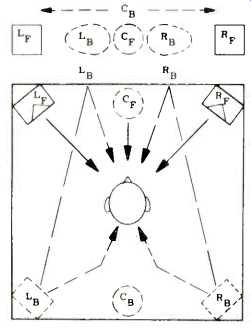
Fig. 8-Image formation. SQ encoded record played on a stereophonic system.
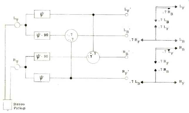
Fig. 9-Block schematic diagram, basic SQ decoder.
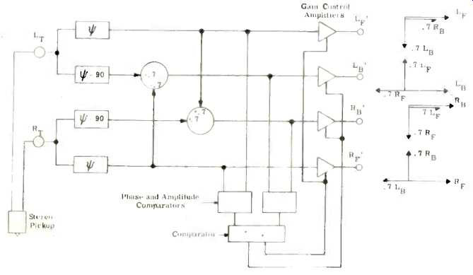
Fig. 10-Block schematic diagram, SQ matrix decoder with logic added.
Logic Directed Decoder
Our ultimate goal, however, was to provide matrix system performance which would be indistinguishable from that obtained with the discrete system. It is possible to achieve this goal by virtue of three remarkable psychoacoustics phenomena we have all experienced:
… that in a normal living room there is …. that a source of a continuous steady- …with ease.
2. The finding that a varying source of sound, such as speech and music can be readily localized.
3. The precedence or Haas effect,' which teaches us that when two or more similar sources are present, the ear credits the one heard first with being the source of sound. Thus, if we can provide an electronic logic to instantaneously enhance the relative strengths of the dominant sources produced by the matrix, and similarly attenuate weaker sounds, we should be able to give the listener the complete experience of four discrete channels.
The control function performed by the SQ logic is shown diagrammatically in Fig. 10. While the matrix portion is identical to that in Fig. 9, the output amplifiers have voltage controlled gain characteristics responding to pre-ordained amplitude and phase positions of the transferred signals, as sensed by the logic. For example, the existence of one of the front channel signals results in the generation of two signals transferred to the back channels which have identical amplitudes and which are in a precise quadrature orientation.
The comparator senses this relationship and causes the front channel gains instantly to be enhanced, while the back channels are rapidly attenuated. Thus, the listener hears only the appropriate front channel signal regardless of his orientation in the room. By contrast, if one of the back channel signals is momentarily predominant, the reverse effect takes place; the front channels are attenuated and the back channels enhanced. The resulting quadraphonic field provides a total awareness of the four independent channels of the master tape. With single channel signals present, the logic maintains the appropriate channel constantly "open," and greatly attenuates the transferred signals relative to the main signal; thus, transmitting substantially discrete channels of information.
Recording Procedures
Every competent artist and producer learns how to obtain best results from a particular medium, and SQ is not an exception: Caution should be exercised to maintain phase integrity of common "panned" signals. Panning across the diagonals or splitting a signal four ways between the channels requires a special encoder connection (on newer encoders available with a switch). Ordinarily, signals panned to center-back will be heard only in the quadraphonic and stereophonic modes, and if they are to be present in a monophonic display special circuit arrangements are needed-so it is best to avoid the center-back soloists.
Some producers, who strive for special effects, find it desirable to "mix" the SQ program using an encoder-decoder combination in the monitor circuit until they develop a "feel" of the system.
However, with the vast majority of instrumental and orchestral performances, the original quadraphonic master tape is simply converted into the SQ record by connecting it to the input channels of the encoder and conveying the encoder output to the conventional disc recording chain.
Decoding either with the SQ matrix or matrix/logic decoder produces a realistic and faithful reproduction of the quadraphonic master tape.
Conclusion As we conclude our review of quadraphonic disc developments, I would like to leave you one last thought: There is much more to quadraphonic high fidelity than may be expressed by any single performance parameter: Frequency response, output level, signal-to-noise ratio, playing time, precision of directional localization, transmission through AM radio systems, equipment cost and complexity, and compatibility with 100-million record players and FM-multiplex radios-all these must be considered. To do less would be an act of irresponsible engineering.
Much has been made of "discreteness" of quadraphonic carrier-type discs, and even our own initial developments used carriers. We found that while a carrier disc is able to approach discrete performance, it does so at the expense of other performance parameters, and only through a precarious balance of several complex processes, involving not only matrixing, but also compression, carrier modulation, ultrasonic disc recording and reproduction, demodulation, expansion, and reverse matrixing-often resulting in a troublesome and unstable action.
On the other hand, the SQ matrix provides us with a simple and competent quadraphonic system. The SQ encoder reorders the four corner signals from the original master tape into two pairs of orthogonal modulations and places them on the disc retaining all the qualities of the standard recording processes. Playback is done with standard stereophonic equipment followed by matrix decoding into four channels carrying predominantly the four corner signals, and within the front and back channel pairs retaining complete channel discreteness of the original master tape. Full 360° panning fidelity and compatibility with all phonographs and broadcast processes is retained. An electronic logic is provided to augment the front-back channel separation of the matrix, resulting in a performance which is difficult to distinguish from the original discrete four-channel master tape.
Since there appears to be no limit to human imagination and perseverance, we expect that experiments with carrier discs will continue--figuratively speaking--hacking in that direction against all odds. We observe that the choice of design parameters of the presently offered carrier discs does not appear to provide an optimum system configuration.
Some optimization; indeed, appears to be feasible, and there even have been suggestions made about using the SQ matrix for the basebands of the carrier discs and of discrete broadcasting systems. While we encourage these approaches, we also commend to the attention of their proponents that the SQ logic-directed matrix, by itself, without the use of carriers, is a more efficacious and equally satisfying way of achieving a realistic, fully compatible, quadraphonic performance.
References
1. See, for example, Robert E. Doherty and Ernest G. Keller, Mathematics of Modern Engineering, Vol. 1; John Wiley & Sons, Inc., New York, 1936,
p. 63.
2. Benjamin B. Bauer, Arnold Schwartz and Arthur J. Gust, “Transient Response and Intermodulation Studies in Phonograph Reproduction," J. Audio Eng. Soc., 11, 2, pp. 110-114. (1963).
3. Frank G. Miller, "Stylus Groove Relationships in Phonograph Records." Acoustics Research Laboratories, Harvard University, Office of Naval Research, TM20, March, 1950.
4. T. Inoue, N. Takahashi, and I. Owaki, "A Discrete Four Channel Disc and Its Reproducing System," J. Audio Eng. Soc., 19, 7, 576-583, July/Aug., 1971.
5. Takeo Shiga, Nippon Columbia Co. Ltd. and Duane Cooper, U. of Illinois. (Personal Communication).
6. Benajmin B. Bauer, Daniel W. Gravereaux, and Arthur J. Gust, "A Compatible Stereo-Quadraphonic (SQ) Record System," J. Audio Eng. Soc., 19, 8, Sept. 1971, pp. 638-646.
7. H. Haas, "Uber den Einfluss eines Einfachechos auf die Hörsamke' Von Sprache" (Effect of a Simple Echo on the Intelligibility of …) Acoustica, Vol. 1, No. 2, pp. 49-58 (1951), Translated in J., 20, 2, pp. 146-159 (1972).
Why the FOUR-CHANNEL WAR need to take place
By Leonard Feldman
WITH THE INTRODUCTION of discrete four-channel discs in May, 1972 by RCA and the growing number of other record manufacturers opting for a "matrix" system of four-channel disc production, it becomes clear that the record buying public may once more be subjected to a "war of the discs" such as occurred many years earlier when, after the introduction by CBS of the Long Playing disc, RCA quickly followed with the 45-RPM disc of its own design.
In the case of the 33 versus 45 war, matters were more or less resolved by the hardware producers. Ultimately, three and even four-speed turntables were developed, and adapter discs and/or plug-on spindles were developed to handle the "big-hole" discs placed on conventional spindles intended for the "small hole" variety. To this date, in fact, both types of discs have coexisted in a relatively peaceful manner.
In the case of the RCA discrete disc versus the CBS-SQ, E-V Stereo-4, Sansui, et al matrix systems, the differences in technology, as presently proposed, are so great that in their present forms, matrix discs and discrete discs are totally incompatible insofar as common hardware is concerned.
Faced with the fact that both discrete discs and matrix discs are now available and the additional fact that totally different equipment is needed to reproduce each type, what is the high fidelity enthusiast to do? Should he buy a matrix decoder now, aware that the possible eventual dominance of discrete discs may make his decoder obsolete? Should he equip himself with a discrete demodulator and a new cartridge and deprive himself of the joys of listening to the ever growing number of well produced matrix discs? Must he invest in two set-ups now, to avail himself of the benefits of matrix as well as discrete discs? Faced with this problem, many consumers are likely to just sit back and wait till the "war is over" … an attitude is likely to hurt … the high fidelity….
There Is A Way Out
What we are proposing here (See also Edward T. Canby's Audio ETC article, page 64, June, 1972.) is a rather obvious way out of the dilemma.
Suppose we could produce a disc with the following attributes:
1. It can be played as a compatible stereo disc (or even monophonically).
2. It can be played via a matrix decoder and will achieve the four-channel effects inherent in the matrix system.
3. It can be played via a matrix decoder plus gain riding logic, with the improved separation inherent in such a configuration.
4. It can be played via a "discrete system demodulator" (using a suitable cartridge) and four discrete channels will be recovered.
With such a disc standard, each potential four-channel listener could decide just how much he cares to spend for the new medium. Further, if he decides to start with a simple matrix set-up and later on elects to go the "full route" towards discrete reproduction, the very same discs which he might have amassed over the years could be replayed using the discrete four-channel equipment.
Why Not Matrix the Discrete Disc?
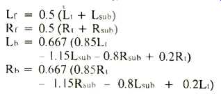
The discrete disc has the capability of accepting four different audio signals (two conventionally cut and two as FM modulation of two sub carriers). Suppose that instead of applying Lr + Lb and Rr + Rb as the conventional groove modulation, we apply the Lt and Rt signals of either the E-V system or the CBS-SQ system.
Suppose further that the modulation used to FM modulate the sub-carriers of the discrete disc consists of newly derived mixtures of all four signals such that subsequent algebraic manipulation would make it possible to extract completely separate L ; Lb, Rr and Rh signals (as opposed to the Le Lb and Rr Rh signals now proposed by RCA). Note, that we have said that any matrix system could be so applied and, while we favor the E-V parameters in terms of their "matrix" playback effects, the present scheme need not be confined to any particular matrix format. That aspect of the problem is one which could be left to the public for ultimate resolution.
To illustrate the idea in more concrete mathematical terms, let us take both the E-V and the CBS-SQ matrix systems in turn and develop the proper "mix" of signals for application to the high frequency sub-carriers of the discrete disc as FM modulation.
E-V Stereo-4/Discrete Disc
The normal left and right groove wall "cuts" should consist of:
Lt = Lr + 0.3Rr + Lb 0.5Rb
And
Rt = Rr + 0.3Lr + Rb 0.5Lb
In addition, let us create the following signals for use in modulating the super audible 30 kHz sub-carrier of the discrete disc:
Lsub = Lf Lb 0.3Rr + 0.5Rb
And
Rsub = RrRb 0.3Lr + 0.5Lb
A suitable demodulator-decoder, in addition to recovering the Lsub and Rsub information from the high frequency sub-carriers, must perform the following algebraic manipulations to recover discrete signals:
If these last four equations are expanded into their individual Le, Lb, Rr and Rb components, it will be found that all but the desired term will cancel, and unity Le, Rr, Lb, and Rb will result. This is because, unlike the simple 4-2-4 matrix techniques, we are now dealing with four different equations, each containing all four signals in varying amounts. With such a condition present, it is possible to provide the necessary de-matrixing coefficients and polarities to reproduce the four discrete original signals.
The CBS-SQ/Discrete Disc
While the introduction of phase shift (the "j" terms) in a matrix system, such as the CBS-SQ System, makes the algebra a bit tougher (and the number of components required considerably greater), the same principles can be applied to this form of matrix system.
The required left-wall and right-wall groove cuts in the SQ disc consist of:
Lt = Le j.7Lb + .7Rb
and
Rt = Rf.7Lb + j.7Rb
If these "mixtures" are applied to the disc as the conventional left and right cuts, the following signals must be added to them as modulation of the high-frequency sub-carriers:
Lsub = Le + j.7Lb .7Rb
and
Rsub = Re + .7Lb j.7Rb
Again, once these signals have been recovered by the demodulator, they must be combined with the conventional Lt and Rt signals in the following four equations:
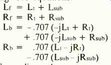
Expanding these terms once more (in terms of original Le, Ri, Lb and Rb) in these equations will result in complete cancellation of all undesired channel components and only the desired Le, Re, Lb or Rb signals will be left at the appropriate outputs of such a combination demodulator-decoder.
Conclusion While we have used specific matrix encoding coefficients to demonstrate the feasibility of this matrix-matrix/ logic-discrete form of disc, it should be clear that' any series of encoding coefficients for a matrix system can be accompanied by a corresponding set of encoding coefficients for the sub channel portion of the program complex, and a suitable series of four dematrixing equations can also be derived which will always result in the recovery of the original signals. We have given this idea serious thought and can think of no valid reason why the two "giants" in the record business should not see in this proposal a ready means whereby immediate stability can return to the record industry--before the war really gets going. In the long run, this can only benefit "them"--and "us."
Quadraphonics--Questions and Answers & How to Convert
Q. I find it almost impossible to place my speakers in the four corners as recommended. What are the alternatives?
A. This is a very common dilemma.
Sometimes there is a certain domestic opposition to the capturing of the four corners-even if the rear speakers are disguised as coffee tables! And in many instances it is not convenient to have the listening position in the center of the room. Furthermore, corners are not necessarily the best positions anyway. One alternative placement is shown in Fig. 1. The rear speakers need not be placed in the corners but in any case the signal level should be somewhat lower than the front channels.
Another possibility is reversing the rear speakers so they "fire" at the walls. Figure 2 shows the Sansui "Front 2+2" arrangement preferred by some people as it puts them outside the sound image.
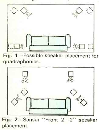
Fig. 1--Possible speaker placement for quadraphonics.
Fig. 2--Sansui "Front 2+2" speaker placement.
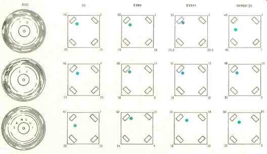
Fig. 3--Power distribution of the various systems when …. to the Left-Front. The dot shows the ….
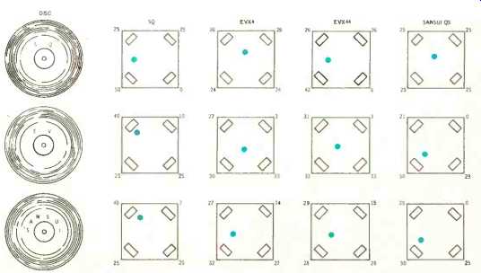
Fig. 4--Power distribution of the various systems when a signal is applied to the Left-Rear. The dot shows the apparent source.
Q. Do the rear speakers have to be identical with the front speakers? A. For the best results, yes. If you have to compromise, choose systems by the same manufacturer. For instance, if your main speakers are ADC 303AX's, use 404's; if they are AR 3a's, buy AR 4's or 5's. Irregularities in the frequency response will tend to cause image shifting.
Q. Supposing I buy a receiver with built-in decoder now, such as the Fisher 801 or Lafayette LR-1500TA, what do I need to play discrete records when they eventually appear?
A. To play the RCA-JVC discs, you will need a discriminator type of decoder and possibly a suitable cartridge.
Details of these should be available soon. It is possible, but unlikely, that some conventional cartridges will be able to play these discrete records without wiping out the 45 kHz signal--at least this is one of the objectives.
Q. What is logic circuitry?
A. This is sometimes called "gain riding," and the effect is to increase matrix separation. When a strong signal appears in one channel, the logic circuit senses it and automatically reduces the gain in the other three, significantly reducing the ghost images. It goes without saying that great care must be taken to avoid image shifting or other annoying effects. One of the first circuits to use gain riding was the original Scheiber, now used by Electro Voice.
Q. How compatible are the various matrix systems? Can I play an SQ record through a Sansui decoder, for instance? A. An article on compatibility and results of practical tests appeared in our March issue. Since then we have received more information on the new Electro-Voice EVX-44 decoder and we are indebted to Howard Durbin of E-V for the results tabulated below.
Figure 3 shows the power distribution of the various systems when signals are applied to the LEFT-FRONT channel and Fig. 4 shows the distribution when signals are applied to the LEFT-REAR channel. It will be seen that front compatibility is better than the rear.
As reported previously, most of the differences tend to be masked by room acoustics.
How to convert to quadraphonics?
The easiest way is to buy a decoder amplifier and two loudspeakers. The diagram shows the basic arrangement of a decoder-amplifier. Output from the tape sockets of the main amplifier or receiver is taken to the decoder which synthesizes the signal into four channels, two being taken back to the receiver and two amplified to some 10 to 20 watts or more for the rear speakers. A switch changes the type of matrix used or by-passes it for normal two-channel stereo or discrete four-channel tapes. The unit can be connected between the preamplifier and power amplifier if so desired.
Note that phasing is important-not only between the front pair but between front and back. There is no guarantee that signals emerging from the rear amplifier will be the same phase as those at the front. As far as we know, no decoder-amplifiers are fitted with a phasing switch-which is a pity.
Fortunately, it is not that difficult to check phasing and the best way is to feed in a mono signal to a rear channel and one front channel, adjust the balance control accordingly, and then test for phase in the usual manner.
In other words, the signal should appear to come from a point midway between the speakers rather than sounding like two separate sound sources.
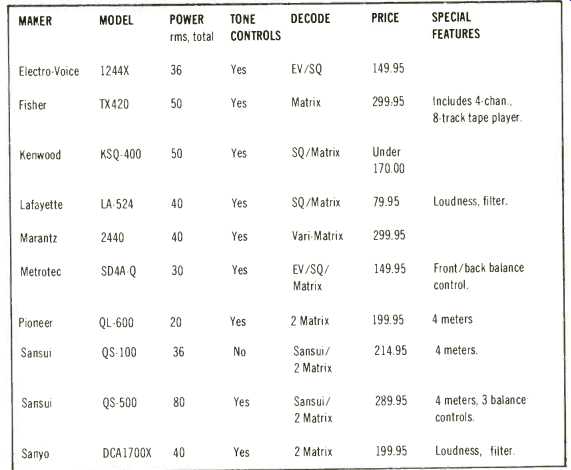
Some units are fitted with tone controls, some have meters-take your choice. A list of those available appears here, but no doubt many others will be on the market before very long. Two models, the Sansui QS-100 and the Lafayette LA-524, are reviewed in this issue as well as the Dynaco SCA-80Q, which is a complete amplifier using the Hafler circuit to produce four separate channels from any two-channel source.
Also reviewed is the Fisher 801-a complete four-channel receiver. (See page 44.)
The New Sansui "20 dB" Matrix
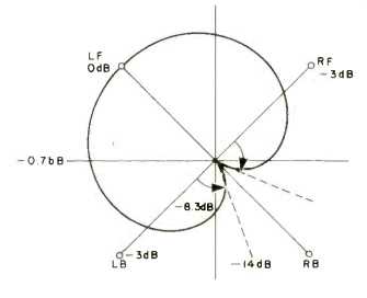
Figure 1
Crosstalk is an unavoidable consequence of any matrix system but separation can be increased by logic circuitry or gain riding. A high amplitude signal in one channel is increased at the same time the gain of the other channels is decreased, thus reducing "phantom images." Now Sansui has come up with an alternative system which they call the 20 dB system or Vario-Matrix. This varies the output signals by changing the matrix itself in terms of phase and amplitude. Control signals are produced by phase discriminators which detect the front back and left-right distribution of the input signal. Figure 1 shows the output sound pressure response of a Sansui QS decoder when a signal is fed to LF. If the LB' decoder matrix angle is altered as indicated by the arrow, the crosstalk of the LF signal contained in the LB' decoder output gradually decreases.
When the LB' matrix angle finally coincides with the RB' matrix angle, the separation between LF' and LB' becomes infinitely large. However, whatever signal exists in LB is only attenuated by-3 dB. Now, if the LB' -0.7bB decoder gain is boosted by +3 dB simultaneously as the LB' matrix angle is shifted to the RB' position, then the LB signal will appear at the LB' output terminal, minus any crosstalk from the LF signal. As the matrix is symmetrical, the variation will work in the same manner from signals in all 360 degrees.
The variable matrix is controlled in the front-back direction in accordance with the following equations:
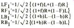
LF1'=1/ J2 { (1+f)L+(1-f)R RF1'=1/ (1+f)R+(1-F)L} LB1'=1/ J2 ((l+b)L-(1-b)R RBl'=1/ J2 {(1+b)R-(1-b)L}
Similarly, it is controlled in the left right direction according to these equations:

LF2'=L+QR LB2'=L-QR RF2'=R+rL RB2'=R-rL
From the above two conditions, the matrix varies according to the following equations:
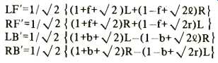
LF'=1/ J2 1(1+f+ 21L+(1-f+ 2Q)R} RF'=1/ J2 { (1+f+ J2)R+(1-f+ J2r)L LB'=1/ J2 { (l+b+ J 2)L-(1-b+ J2Q)R } RB'=1/ J2 { (l+b+ J2)R-(1-b+ J2r)L}
How does the Vario-Matrix work? I heard the system in Los Angeles and was very impressed. Separation was excellent with no sign of image shifting or irregularities produced by early logic circuits. My only criticism concerned the possible high cost but it was claimed that the use of IC chips would bring the cost down considerably. Moreover, a low priced version is feasible using only front/back control. The system is not compatible with the CBS SQ--a pity.
-G.W.T.
Equipment Test Reports:
Two Decoder-Amplifiers
Lafayette LA-524 Quadnaural SQ Decoder/Auxiliary Amplifier
MANUFACTURER'S SPECIFICATIONS
Power Output: 60 watts total (IHF) at 4 ohms.
Distortion: 0.1%. Power Bandwidth: 35 to 30,000 Hz.
Hum and Noise: -70 dB.
Input Sensitivity: 275 mV.
Facilities: Bass and treble controls, loudness filter, high filter, mono-stereo switch, headphone jack.
Decoding: CBS SQ and COMPOSER.
Price: $79.95.
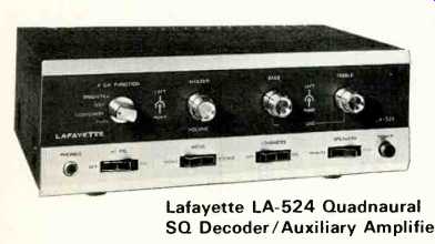
Model LA-524 is a remarkably compact decoder-amplifier and is probably the most inexpensive solution to the problem of quadraphonic conversions to date. Power output of over 20 watts per channel is ample for most requirements and there are both SQ and COMPOSER (ambience) facilities plus loudness, filter, and tone controls. The function switch on the left of the front panel has four positions: DISCRETE, SQ, COMPOSER, and F PLUS R (which parallels the left-front channel with the left-rear, and the right-front with the right rear). Next comes the MASTER VOLUME control, BASS and TREBLE controls-all dual-concentric types. At the bottom of the panel is a phone jack and power switch plus four rocker switches for FILTER, STEREO-MONO, LOUDNESS, and REMOTE speakers. Figure 1 shows the rear panel with the various input and output sockets. On the right is a slide which increases the sensitivity by about 6 dB for, use with higher gain receivers than Lafayette models, etc. This rear panel also contains an unswitched 400 watt a.c. convenience outlet, located in the lower left-hand corner. Just above it and to the right is a small inset and covered box containing the 1 amp speaker fuses. The remote speaker outlets are set up for standard phono plugs. Figure 2 shows the inside view.
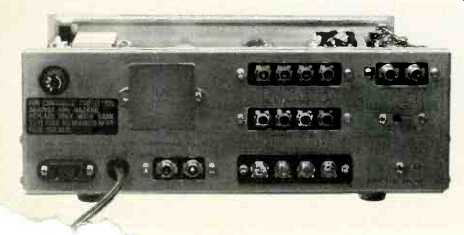
Fig. 1-rear panel.
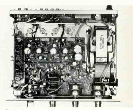
Fig. 2-Inside view.
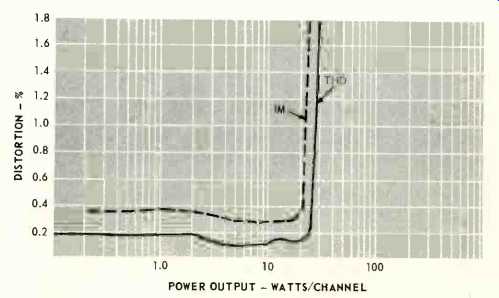
Fig. 3-Showing IM and THD distortion, both channels driven, 4 ohm load.
Brief Circuit Description
A total of 11 transistors are used for the SQ and ambience circuits, then comes an amplifying stage, a Baxandall tone control arrangement, followed by the drivers and output stages which employ seven transistors for each channel. Speakers are capacitor coupled and the d.c. supply is 39 volts. Two transistors for each channel are used to amplify the front channel signals before feeding them back to the main amplifier. Altogether, no less than 33 transistors, 2 diodes, and 2 thermistors are used!
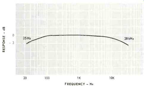
Fig. 4--Power bandwidth.
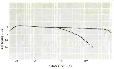
Fig. 5--Showing filter characteristics.
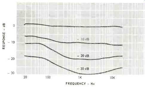
Fig. 6--Loudness control at-10,-20, and-30 dB.
Figure 3 shows the THD and IM distortion and it will be seen that the rms equivalent power comes out at more than 25 watts per channel. Power bandwidth was 25 to 28,000 Hz, as shown in Fig. 4. Overall frequency response was-2 dB at 12 and 60,000 Hz-and only 4 dB down at 100 kHz as shown in Fig. 5, which also shows the effect of the low-pass filter.
The loudness-control characteristics are shown in Fig. 6.
The tone controls had a lift of 8 dB and cut of 10 dB at 10,000 Hz and a lift of 10 dB and cut of 13 dB at 40 Hz. Hum and noise was-60 dB under the worst conditions (volume control at maximum, sensitivity switch set for highest gain). On test, the 524 was connected to the TAPE IN/our sockets of a Sony 1130 amplifier and the outputs taken to four Dyna A-10 loudspeakers. A few minutes was spent in balancing up and then a four-channel tape was played with the switch set to DISCRETE. No problems-no trace of hiss, hum or distortion.
Then several SQ discs were played and again, results were completely satisfactory. Later, ordinary two-channel material from records and FM was played and it was found that the COMPOSER position occasionally gave better results, mainly when ambience only was required for the rear channels.
However, after a few days, I found myself leaving the switch in the SQ position and adjusting the balance for best results.
Summing up, the Lafayette 524 offers remarkable value for money and can be recommended to the attention of those who want to convert to four channel on a limited budget.
--T. A.
===============
Sansui QS-100 Four-Channel Rear Amplifier
MANUFACTURER'S SPECIFICATIONS
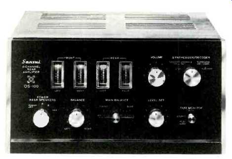
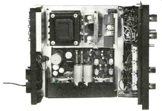
Fig. 1-inside view.
Input: 200 mV. Output Level (front): 775 mV. Recording Output (two-channel): 200 mV, 30 mV DIB. Frequency Response: 20 to 20,000 +/-1 dB. Synthesization of Rear Channel Signals: Sansui phase modulation and matrix.
Hum and Noise: Less than -70 dB.
Power Output: 18/18 W at 4 ohms.
THD: Distortion less than 0.8%. IM: Less than 1.0%.
Power Bandwidth: 25 to 40,000 Hz.
Dimensions: 9 in. W by 5 in. H by 11 in. D. Price: $214.95.
Basically, the QS-100 comprises a Sansui decoder with a two-channel amplifier for the rear speakers, but it does offer many other features. For instance, there is provision for two other matrix arrangements for use with mono or two-channel sources and there is a switch position for a second …. Sansui advocates a position called e front in certain rooms (and with some kinds of music) and whatever the advantages might be, the switch certainly offers instant comparisons-assuming you have six loudspeakers handy! (See page 38.) The keen experimenter will find the four meters very useful and the extra price fully justified. Reading from left to right, the controls are as follows: Speaker and ON-OFF (Pair A, Pair B, and both), BALANCE control (left-right, front and rear simultaneously), then the MAIN BALANCE control in the center. This is a slide unit and it adjusts the balance between the front and rear channels. To the right is the LEVEL SET control, which adjusts the input signals, and above that is the VOLUME control, which operates on all four channels. At the extreme right is the SYNTHESIZER-DECODER switch with positions for two channel, two matrix positions called CONCERT HALL 1 and 2, then the Sansui decoder, and finally discrete four channel. The lever switch underneath is for tape monitoring. Figure 1 shows an inside view and Fig. 2 shows the rear panel. The preset control is for adjusting the rear channel level, and above that is a standard DIN socket for a tape recorder. At the bottom, on the left is a voltage selector covering the 220-240 volt range as well as 110-117 volts.
Circuit Details
Front two-channel, or four-channel discrete signals are taken direct to a transistor stage and a meter amplifier and back to the output sockets of the receiver. Signals pass through the appropriate matrix or decoder circuits as selected by the switch. A total of four transistors, five modules, and 10 IC's are employed for these circuits. The power amplifiers use six transistors each in a fairly conventional circuit with a complementary pair driving a NPN output stage with capacitor coupling to the speaker. The stabilized power supply uses three more transistors and the unregulated output is about 45 volts.
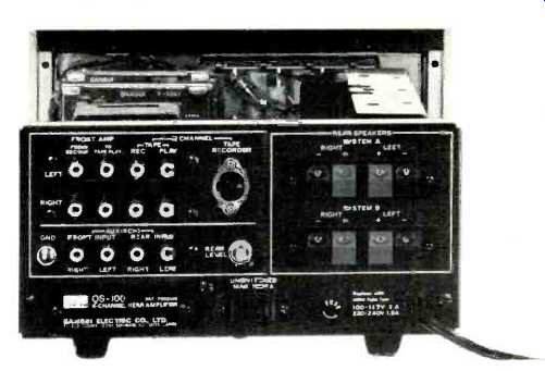
Fig. 2-Showing rear panel.
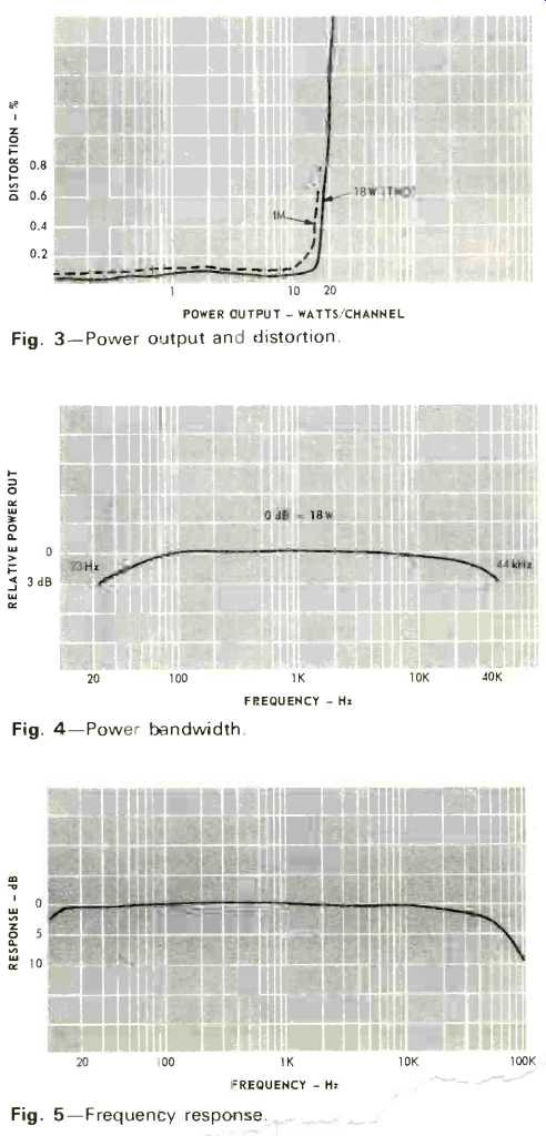
Fig. 3-Power output and distortion.
Fig. 4-Power bandwidth.
Fig. 5-Frequency response.
Performance
Figure 3 shows the power output per channel with 4 ohm loads, both channels driven simultaneously. It will be seen that maximum output is about 20 watts per channel. Figure 4 shows the power bandwidth-slightly better than the specifications at 23 to 44,000 Hz. The frequency response was only 1.5 dB down at 10 Hz and 8.5 dB down at 100 kHz (see Fig. 5). Signal-to-noise ratio was-72 dB referred to 18 watts, which is excellent. Sensitivity came out at 150 mV for full output from the rear amplifiers, and the stage gain for the front signal was about 6 dB.
The four meters were found invaluable in setting up the QS-100-an operation which requires adjustment of the receiver volume control, preset control for the rear channels, and the unit's volume control. The balance controls are left in the center position and then adjusted last. A Sansui 5000X was used (the unit will work with any receiver, but it didn't seem fair to use my Sony 1130 amp!), and the QS-100 was connected between the tape in/out sockets in the normal manner. The first records to be played were two Sansui-encoded discs and they produced excellent results with good location and a very real sense of actually being there in the concert hall. A third Sansui disc was also played; this was Beverly Sills Welcome To Vienna, which has ambience only in the rear channels. Both the CONCERT HALL I and 2 matrix systems were tried here and both gave acceptable results, although not quite as effective as the decoder. However, some conventional two-channel records sounded better with the switch in one of the CONCERT HALL positions instead of DECODER-but this is a matter of personal taste. Sansui recommends the FRONT 2+2 speaker positions for solo performances, vocal numbers, and small band selections when using the CONCERT HALL matrix systems, but I found position B best for my particular room and also for CBS SQ records. As might be expected, SQ discs gave very good results with some mis location. However, in most cases these deviations would go un-noticed-unless an SQ decoder was used for a comparison.
Records that sounded particularly well, included the Bernstein Petrushka, Switched-On Bach of Walter Carlos, and Ray Stevens' Greatest Hits. Curiously enough, the new Boulez Petrushka sounded almost as good as the SQ Bernstein when played via the decoder! The execution is far superior-a personal view of course, but I can hardly wait for the quadraphonic version! One word of warning; the speaker switch will select either pair A or pair B-or both together, so the rear speaker impedance must be 8 ohms, not 4.
Summing up, the Sansui QS-100 is a well-made unit which can be recommended to those who want a versatile conversion decoder-amplifier with extra facilities. At a price of $214.95, it represents good value for money.
-T.A.
(Audio magazine, Jul. 1972)
Also see: