MANUFACTURER'S SPECIFICATIONS
Speakers: Woofer: Four 12-inch, each channel; Midrange: Four 8-inch direct radiator, each channel; Tweeter: Four diffraction horn, each channel. Crossover Frequencies: 200 Hz, 5 kHz. Crossover Type: 12 dB per octave.
Weight: Woofer: 185 lbs.; Satellites: 30 lbs. each.
Size: Woofer: 31 in. H x 49 1/2 in. W x 24 in. D; Satellites: 43 in. H x 9 in. W x 6 in. D.
Price: $ 1300, utility cabinet; $ 1600, stained wood cabinet.
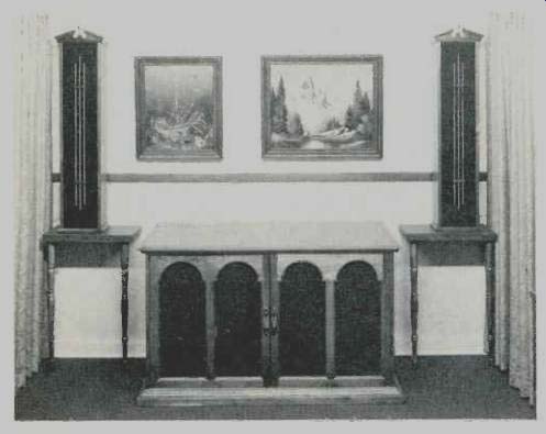
Measuring 31 x 24 x 49 1/2 inches and weighing 185 pounds, which would be considered a massive speaker by anyone's standards, the Frankmann stereo reproducing system is marketed by King Research. And these are the specifications of only the woofer section! The midrange and tweeter speakers are housed in 9 x 6 x 43-inch satellite enclosures meant to be suspended on either side of the woofer enclosure to constitute a stereo installation.
A total of 24 speakers are used in the Frankmann. The woofer section for each channel consists of four 12-inch drivers. These are positioned in a multiple configuration with an equal offset of 13 inches between centers and alternate speakers canted so as to cross-fire into the room.
The left channel and right channel woofers share a common enclosure which is sturdily cross-braced for structural rigidity.
All woofers share this common volume of 16.1 cubic feet with the distinction between left and right stereo woofers made by their physical location with respect to center of the enclosure. While the woofers are housed in a completely closed fashion, there is substantial leakage of air through the woofers, which, together with a common acoustic communication with woofers of the opposite channel, mean that this was probably not designed as an acoustic suspension system and ranks more nearly with a passive radiator vented system than an infinite baffle system.
The woofers cross over at 200 Hz to the satellite enclosures which house midrange and tweeter drivers. These are configured in a line-speaker arrangement with four 8-inch direct radiator midrange speakers alternated with four diffraction horn tweeters. The satellite enclosures are intended to be positioned on the same plane as the common bass enclosure and on either side at a height of 18 to 31 inches from the floor, according to King Research. Since these satellite units each weigh 30 pounds, this reviewer recommends a sturdy support for safety reasons.
Speaker connection is made by means of a screw terminal barrier strip on the rear of the enclosures. Each channel uses a pair of wires from the appropriate amplifier terminals to the rear of the bass enclosure. A flexible wire pair supplied by King Research connects the satellite reproducer to its appropriate terminals also on the rear of the bass enclosure. The terminals are well marked and legible and no difficulty should be experienced in hookup or operation. Each half of the stereo pair is protected by fuses, access to which is available through holders in a recessed cavity on the rear of the bass unit.
The unit received by AUDIO was finished in flat black for custom installation. The only literature supplied to AUDIO by King Research appears to be more nearly associated with a patent disclosure than conventional technical information. This could be very confusing to a purchaser who had not previously had the experience of reading such prose.
No warranty or user oriented instructions accompanied the unit delivered to AUDIO.
Technical Measurements
Figure 1 shows the measured impedance as a function of frequency. Because the woofers communicate through the common enclosure, excitation of one channel causes an interaction with the undriven woofers of the other channel. Because of this, two impedance plots are shown-one with the undriven woofer section unterminated and the other with a low impedance amplifier termination.
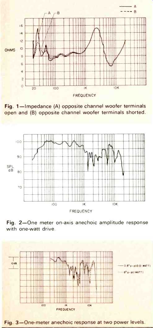
Fig. 1--Impedance (A) opposite channel woofer terminals open and (B) opposite
channel woofer terminals shorted.
Fig. 2--One meter on-axis anechoic amplitude response with one-watt drive.
Fig. 3--One-meter anechoic response at two power levels.
The curve marked A is the unterminated companion woofer measurement and shows two distinct peaks at 27 Hz and 50 Hz in the bass region. This is characteristic of a vented system and in fact the unterminated woofers constitute the equivalent of a passive radiator, or "drone cone." One can anticipate from this that the low frequency response will not be that of a simple rigid closed box.
The curve marked B is made with a short circuit across the undriven woofers and clearly shows that the double resonance is due to passive radiator effects and not to moving boundary problems in an otherwise rigid enclosure. The B curve is more characteristic of behavior when driven by stereo amplifiers of high damping factor and this configuration was used for all other spectrum tests.
The relatively broad impedance peak at around 2.5 kHz and dip at 7 kHz do not occur at the stated higher frequency crossover of 5 kHz. For the majority of program material, the Frankmann can be considered to be an 8-ohm system as specified.
The one-meter anechoic amplitude frequency response for one-watt input is shown in Fig. 2. The Frankmann is an unusually sensitive system with an acoustic output per watt ranking close to the larger horn radiator systems. The response was measured one meter directly on the axis of symmetry of a satellite which had been placed directly above and in the plane of the woofer cones. Low frequency response is impressive with an acoustic output at 32 Hz well above the midrange output available from many conventional direct radiator speaker systems when driven at the same power level.
The frequency response above 200 Hz, measured under anechoic conditions, is unfortunately very dependent upon the microphone position. This is due to the "broadside array" properties of periodically spaced multiple midrange and tweeter units. A displacement of the space position of the measuring microphone by less than an inch produces quite a different looking frequency response. This substantial space interference may be responsible for an unusual nonlinear property noted during these measurements. The frequency response is a function of drive level. Figure 3 is a measurement of the normalized response at one watt average and 10 milli watts average drive. The detail behavior in the 3-4 kHz and 9-10 kHz range is different for the two drive levels as is the fine detail elsewhere. This effect was completely reproducible as a function of power and was not due to driver damage since at no time was measurement made at power levels in excess of 10 watts average above 1 kHz.
Because the phase response was more dramatically modified by drive power level and completely changed characteristics dependent upon microphone position, no phase plot is included for the Frankmann. This reviewer did not feel that it would be possible to provide a representative phase measurement. The Frankmann is almost totally non minimum phase above 1 kHz.
The three-meter room response is shown in Fig. 4. To make this measurement, the bass enclosure was floor-mounted and placed against a flat wall. The satellites were also placed against the same flat wall as a user might prefer to mount them and in a manner indicated in literature supplied by King Research. The satellites were oriented with the long axis vertical and the lowermost part 31 inches above the floor.
The satellites were placed slightly over one meter to the left and right of the center of the bass enclosure. Only the left channel stereo speakers were used for test and the right channels had the terminals shorted to simulate an amplifier source. The microphone was placed one meter above the floor and three meters distant from the front surface of the satellite left channel speaker.
The frequency spectrum of the first ten milliseconds of sound arrival are shown. The two measurements of on-axis and stereo listening are displaced 10 dB for clarity of presentation. Much of the midrange-robbing interference evidenced in the anechoic measurement is filled in by floor, ceiling, and bass enclosure sound scattering when listening in a room.
The substantial drop in response at 220 Hz for the on-axis position is due to the fact that the acoustic position of the woofer is sufficiently far behind that of the satellite that its contribution does not arrive in time to be passed through the time gate of this 10 millisecond measurement. The implications of this three-meter measurement are that overall sound balance will be good between 300 to 10 kHz for most seating positions, but pinpoint stereo sound images should not be expected. Additionally, the timbre of percussive instruments with fundamentals in the octave around middle C will change with listening position. Instruments which have a more steady state characteristic, such as organ, will not be bothered by this effect and should be accurately reproduced to the satisfaction of many listeners.
The anechoic polar energy pattern for the satellite mounted in the preferred vertical position is shown in Fig. 5. There is, in fact, a preferred left and right satellite position due to an angular offset of the front mounting panel. This is not mentioned in the literature which King Research supplied; however, it would appear that the satellites may be mounted so that the drivers each more nearly face into the listener position or away from him. To prevent ambiguity, the polar azimuth plot of Fig. 5 was made with the frontal axis aligned with the axis of the speakers themselves, which means that if the enclosure were placed flat against a wall, the wall would be represented by a line passing through the center of this plot and going from about the 9:30 clock position to the 3:30 clock position.
Figure 6 shows the polar energy pattern for the vertical, or elevation, axis of the satellites when mounted in the preferred position. The effect of multiple drivers on a total energy basis is evident in this measurement. Substantial floor and ceiling reflection is to be expected from the satellites, according to this measurement.
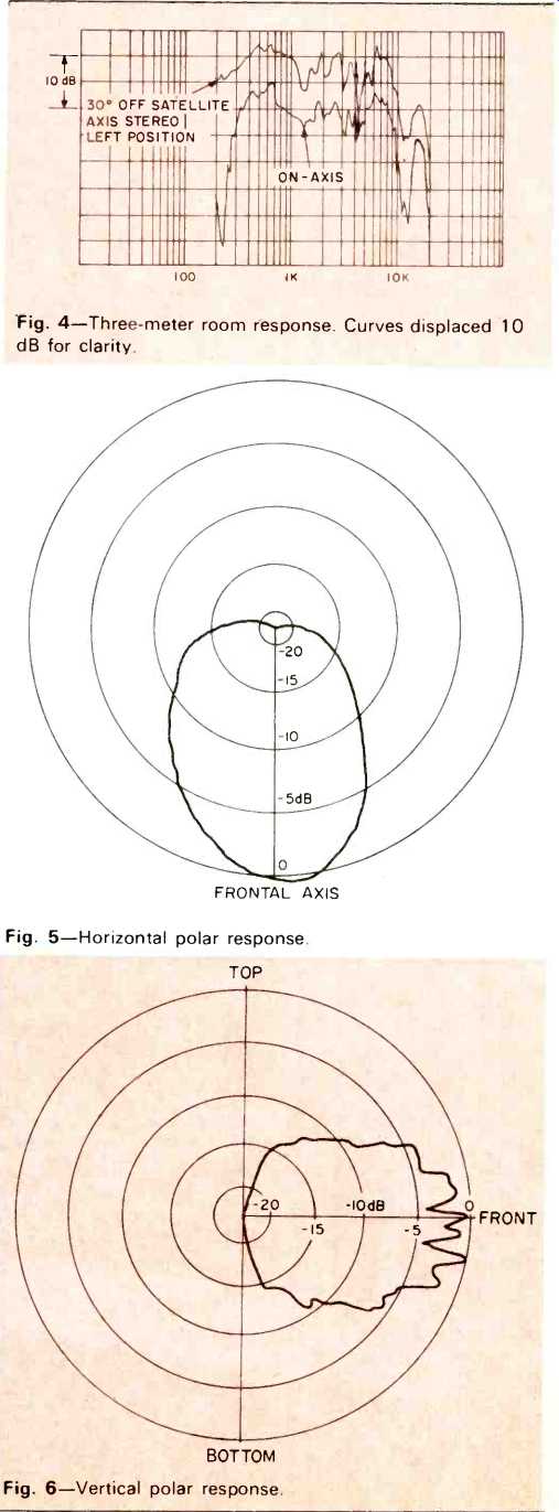
Fig. 4--Three-meter room response. dB for clarity.
Fig. 5--Horizontal polar response.
Fig. 6--Vertical polar response.
Because the bass enclosure handles energy below 200 Hz while the satellites cover the musical range above that frequency, the harmonic distortion measurements were made separately. Figure 7 shows the harmonic distortion for E, and A, which are handled by the woofers, while Fig. 8 shows the measurement for A, and A4, which the satellites handle.
If you like pipe organ and have a large enough listening room, the Frankmann can provide thrilling reproduction. During all such tests, the output of the test microphone is monitored on an oscilloscope and listened to through an auxiliary speaker to note any signs of distress. No enclosure buzzing or driver problems were noted except for the second harmonic distortion at E,. The use of multiple drivers clearly relaxes the demand on any single speaker, enabling high intensity to be achieved at low distortion values.
To test the woofer which crosses over at 200 Hz, the inter modulation test was performed for the effect of E1 (41.2 Hz) on D2 (146.8 Hz). The intermodulation is plotted in Fig. 9 as a function of power. Again, the Frankmann had a very low distortion. The intermodulation was almost purely amplitude modulation with virtually no phase modulation in evidence.
A spectrum analyzer display during this test disclosed that the harmonic distortion on E1 was distinctly higher than the side bands about D, due to E,. This is a desirable characteristic.
The crescendo handling capability of the Frankmann is extremely good. Musical test tones of A, and A4 were not measurably modulated by superimposed broad-band noise with an average power level 20 dB above those tones even when the instantaneous noise peaks achieved 200 watt. Assuming an average acoustical transfer of 95 dB per watt at one meter, this means that an 87-dB tone is not measurably suppressed by a crescendo of incoherent tones with instantaneous peak levels of 117 dB when measured at one meter. If you like it loud, this speaker will give it to you.
The energy-time plot is shown in Fig. 10. This is a direct measurement of the arrival time pattern of total energy density for spectrum components from d.c. to 20 kHz. The Frankmann does not fare so well in time delay distortion. The equivalent acoustic positions of selected physical components is indicated on this figure. The measurement is made one meter directly in front of a satellite enclosure which has eight speakers. The speaker directly in front of the microphone is a diffraction horn tweeter. This is what is labeled "center tweeter" on this figure. On either side of this tweeter are 8 inch direct radiators which are labeled "middle speakers." On the outer side of each of these direct radiators are diffraction horn tweeters and then direct radiators, labeled "outer transducers," to complete the eight radiating elements.
What is labeled "enclosure lateral extremity" is the time that would be taken by a sound wave expanding from the center tweeter as a spherical wavefront to traverse the major length of the enclosure and radiate from the acoustic discontinuity due to the enclosure-air boundary.
The voice coils of the horn tweeters lie behind the front panel by a number of inches. The voice coil of the direct radiators is nearer to the mounting surface and a cone compressional wave which travels much faster than sound in air would, if not elastically terminated by the cone surround, launch a sound wave that would appear to come from near the position of the front panel. This would be expected to be very low in energy.
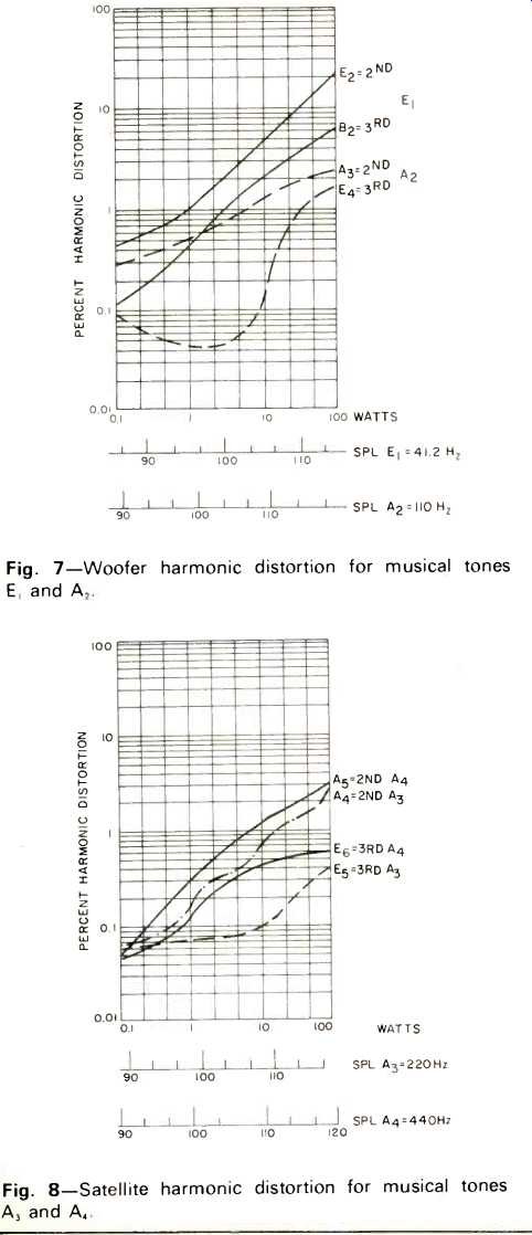
Fig. 7--Woofer harmonic distortion for musical tones E1 and A2.
Fig. 8--Satellite harmonic distortion for musical tones A3 and A4.
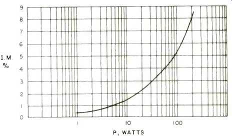
Fig. 9--Intermodulation distortion of musical tone D3 (146.8 Hz) by E1 (41.2
Hz) mixed in equal power.
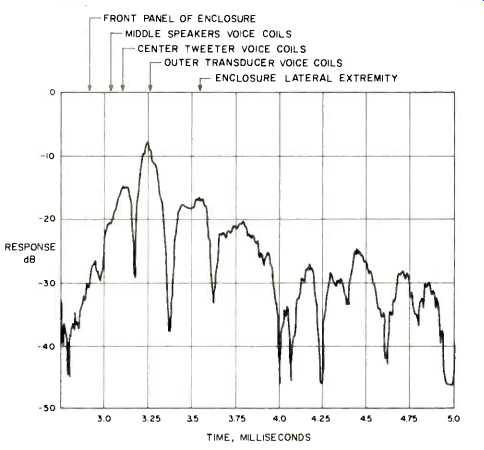
Fig. 10--Energy density for first two milliseconds of sound for perfect
impulse with all frequency components from 20 Hz to 20 kHz.
Listening Test
The Frankmann represents a challenge for listening for a variety of reasons, not the least of which is its bulk and the requirement for satellite mounting. When you purchase this system, have a good idea where you want to place it since it is one piece of furniture that does not lend itself to experimentation in placement.
For listening test, the Frankmann was mounted against a flat wall with the satellites also against the wall but raised so that the bottom of the satellite enclosure was just below the top of the bass enclosure.
The first impression is that of a lot of sound for a little power. A ten-watt amplifier would supply all the sound most people would want, if the amplifier were clean. This is a mixed blessing since amplifier hiss and hum will be quite a bit more audible with such an efficient system.
One expects, and gets, a lot of clean bass from the woofers. However, there is one listening problem with the bass which this reviewer found serious and could not solve completely. Stated simply, the natural tendency when listening to a geometrically symmetric stereo installation like the Frankmann, is to sit with the bass section in front of you and the satellites symmetrically displaced to front left and front right. When you do that, there is generally a wall somewhere behind you that is parallel to the wall against which the Frankmann is placed. This is a classic setup for a grave room normal mode. Advertising copy to the contrary, the physics of a localized bass source with that geometry will create standing waves. In the case of the Frankmann, this created the sonic illusion of pipe organs with missing notes in the lower register and tympani with, to this reviewer, an unnatural change in timbre, when the Frankmann was positioned against a wall which had an uninterrupted path of about 32 feet. This reviewer can recommend the Frankmann bass unit only for very large rooms when the Frankmann was positioned against a wall which had an uninterrupted path of about 32 feet. This reviewer can recommend the Frankmann bass unit only for very large rooms when you are sitting far back from the speakers.
The satellite units provide a well balanced midrange from the standpoint of frequency response, but the stereo imagery is diffuse and does not lend itself to pinpoint localization. Massed choral groups, organ music, and symphonic material were well reproduced with the exception of the previously mentioned room mode problem. Percussive instruments, single vocals, and piano were not reproduced to this reviewer's satisfaction.
The satellites must be oriented vertically. A brief experimentation with listening to the satellites spaced horizontally soon verified why. The polar fingering in a horizontal direction is so substantial that even without moving one's head, stereo center stage vocalists hopped kangaroo-fashion from left to right as they performed.
A very interesting effect was noted when wide-stage material was reproduced in a location where the opposite wall spacing was only 14 feet. This close spacing was deliberately chosen to represent reproduction in smaller rooms. If one turns his back so the sound source is to the rear, the stereo quality is almost as good as that when facing the speakers. This would suggest that smaller problem rooms could be used with the Frankmann if the speakers were directed so as to increase the ratio of reverberant to direct sound. In any event, the Frankmann can provide both outstanding bass performance and low distortion high sound level in very large rooms.
-Richard C. Heyser
Addendum
In our May, 1974 equipment profile of the ESS preamplifier and Model 200 amplifier (page 56), we inadvertently inserted an incorrect graph. Here is the proper version, with our apologies for the error. -Ed.
Fig. 14--THD at 1 kHz versus power and IM distortion versus power. Note that right channel IM distortion fell to levels achieved by the left channel with a small adjustment of the bias pot.
(Audio magazine, Jul. 1974)
Also see:
Frazier Concerto Model F-10W-37 speaker (Equip. Profile, Mar. 1974)
Fairfax FX-300 Speaker System (Nov. 1972)
Fisher ST-425 Speaker System (Equip. Profile, Jan. 1975)
= = = =