Workbench PROfiles
MANUFACTURER'S SPECIFICATIONS
Distortion Measurement Accuracy: 20 Hz to 20 kHz,-±1 dB; 10 Hz to 50 kHz, +1,-2 dB; 50 kHz to 110 kHz,+1.5,-4 dB.
Fundamental Rejection: 10 Hz to 20 kHz, over 100 dB; 20 kHz to 50 kHz, over 90 dB; 50 kHz to 110 kHz, over 86 dB.
Distortion Introduced by Instrument (Inputs over 1 V rms): 10 Hz to 20 kHz, below-95 dB; 20 kHz to 30 kHz, below-90 dB; 30 kHz to 50 kHz, below-85 dB; 50 kHz to 110 kHz, below-70 dB.
Residual Noise (fundamental frequency setting below 20 kHz, 80-kHz filter in, source resistance no more than 1 kilohm): Less than-92 dB, referenced to 1V.
Input Level for Distortion Measurements: 30 mV to 300 V rms (100-mV range minimum).
Input Impedance: 100 kilohms, ±1.0 percent, shunted by less than 100 pF from input high to input low.
Oscillator Distortion (600-ohm load minimum, less than 3 V output): 10 Hz to 20 kHz, less than-95 dB (0.0018 percent) THD; 20 kHz to 30 kHz, less than-85 dB (0.0056 percent) THD; 30 kHz to 50 kHz, less than-80 dB (0.01 per cent) THD; 50 kHz to 110 kHz, less than-70 dB (0.032 percent) THD.
Output Resistance: 600 ohms, ±5 percent.
Oscillator output terminals remain terminated with 600 ohms in Off position of oscillator level control.
Price: $1900.00.
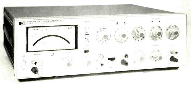
Since the earliest days of high fidelity, there has been a steady increase in technical sophistication and an improvement in all measurable parameters. One inevitable consequence of this trend has been the birth and growth of electronic equipment specially designed for audio measurements. Here is one fine new instrument from Hewlett-Packard, the Model 339A Distortion Analyzer/Oscillator.
Coming from the Loveland, Colorado, instrument division, this new machine joins a number of similar products from the same firm, such as the 4333 and the better-known 331 334 series. However, this is the first instrument from H-P that includes a low-distortion signal source. With the internal oscillator, a tracking notch filter, and a sensitive true rms responding voltmeter, the 339A has the complete capability of making the familiar THD+N measurements as defined in IHF standard A-202-1.17. Additionally, the voltmeter and oscillator may be used independently to provide various other measurement capabilities, including signal-to-noise ratio and level-flatness testing.
In the distortion analyzer mode, or more properly the distortion meter mode, the instrument can measure total harmonic distortion and noise from 0.01 percent to 100 percent full scale in nine ranges. While the fundamental frequency range is from 10 Hz to 110 kHz, the rejection and voltmeter circuits have sufficient bandwidth to provide good measurements for harmonics as high as 330 kHz.
While simultaneously tuning the notch filter, the oscillator has switch selectable frequency settings with two significant digits of resolution. A variable control is also provided to permit operation at intermediate, but uncalibrated frequencies. An output attenuator with seven 10 dB steps and a 10 dB vernier give good set-ability for output levels from less than one millivolt to greater than 3 volts across 600 ohms or greater than 6 volts across high impedance loads.
H-P has placed great emphasis on making this instrument fast and easy to operate. With automatic set level and the coupled oscillator/analyzer tuning, this instrument nulls without operator assistance once the desired frequency is selected. Automatic set level operates over some 10 dBV of input range. When this range is exceeded, one of two LEDs above the input level control indicates the proper action required by the operator for a valid measurement.
In similar fashion, two LEDs located above the frequency tuning dials direct the operator quickly to the appropriate setting needed when tuning to an unknown input frequency.
For convenience in making relative a.c. level measurements, the meter has a relative level adjustment that allows the user to bring any input level up to the "0" dB point on the meter. Another operating convenience is the oscillator level function. When the function selector is set to Osc level, the a.c. voltmeter circuits are connected internally across the front panel oscillator output terminals, permitting the user to see exactly what the signal level across the input of the device under test is.
A good selection of filters (400-Hz high-pass and 30- or 80-kHz low-pass) with 18 dB/octave rolloffs are selectable in any combination on all functions. Broadcasters will appreciate the self-contained AM detector and the switchable normal/VU meter ballistics.
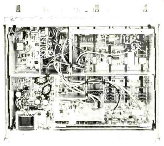
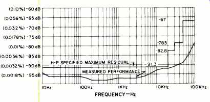
Fig. 1--Residual THD and noise vs. frequency with oscillator output unloaded, 2 V rms output; input range, 3 V full scale; all filters off.
Figure 1 shows the actual and the specified performance for distortion residual under conditions similar to those en countered in a typical preamplifier measurement. The measurement was made by tying the oscillator output to the analyzer input, setting the output level to 3 volts, and setting the dials to selected frequencies. By studying the specifications for the 339A, it can be seen that there are actually four different components to the residual distortion of the unit, 1) in complete fundamental rejection, 2) distortion added by the instrument, called induced distortion, 3) residual noise, and 4) oscillator distortion. In practice, the most significant contributors were the induced distortion and the residual noise of the input and analyzer circuits. Use of the low-pass filters will permit lower measurements, but the residual of the 339A is already so low that it is unlikely that many meaningful audio measurements will be limited by the instrument's capabilities.
As a signal source, the 339A oscillator section is one of the very best available. Not only is the distortion exceedingly low, but the output amplitude flatness was found to be much better than the specified+0,-2dB from 10 Hz to 100 kHz. At 100 kHz, most of the "error" is caused by simple capacitive loading on the 600-ohm output of the oscillator.
From 20 Hz to 20 kHz this particular unit measured about+0,-0.01dB. Frequency setting accuracy was closer to 1 percent than the specified 2 percent, but it will still be necessary to employ a frequency counter when measurements are to be made of RIAA equalization, without the aid of an accurate pre-equalizer. One particularly noteworthy feature of the oscillator is the very fast amplitude settling at low frequencies.
This desirable state of affairs is due to the use of a clever and elegant AGC circuit; it uses a sample/hold to peak detect the instantaneous output amplitude. Incidentally, the oscillator section of the 339A is available separately as the model 239A and sells for $575.00.
The 339A is certain to be good choice for production applications requiring a high-performance instrument. The inherently fast oscillator and notch setting, combined with the automatic set level, make this the fastest responding instrument of its type--especially when viewing the monitor out put directly. The meter is large and easy to read, but the response of the voltmeter circuits is slower than that of the oscillator and notch under most conditions. This particular situation seems to be stimulated whenever one changes filters or the setting of the function switch, particularly with the analyzer set to one of the low distortion ranges. The usual effect is to send the meter pointer beyond full scale in a brisk and vigorous manner. There is one other problem related to the 400-Hz high-pass filter; it seems that this particular filter is quite susceptible to r.f.-type interference. It was occasionally found to be misbehaving when the input had significant high-frequency information, causing peculiar looking residuals on the monitor output and erroneous meter readings. Since the particular unit tested was such an early model, it is entirely possible that these details have already or will have received the proper attention before this article is published.
Grounding in the 339A is intentionally separated between the oscillator and voltmeter/analyzer circuits by the use of a different, floating power supply for the oscillator. In addition, the input and monitor ground may be floated as much as 30 volts above the chassis and power line safety ground. This system provides good rejection of undesired low frequency hum and noise. However, the user should be aware that the 339A does still capacitively tie all grounds together. In a small number of cases, a power amplifier may oscillate when connected to the 339A in the usual manner. If this is found to be a problem with any particular amplifier, try tying the oscillator low side to chassis ground externally and not connecting the output ground to the analyzer at all. This distortion analyzer is not suitable for measuring any amplifier in which both outputs swing with respect to ground or for measuring signals on balanced lines which must remain floating. To per form well with these types of sources, the instrument should have true differential inputs. Unfortunately, a true differential input stage would add a considerable expense to the 339A and it would be difficult to maintain the same fine specifications for distortion and noise.
(Editor's Note: H-P has a fix, in Service Note 339A-1, if this is a problem.--E.P.)
So far as is known to this reviewer, the 339A is one of only two analyzers to employ a true rms responding converter, as opposed to the common average responding rms calibrated detector. Although average responding meter circuits are calibrated to give the correct indication with sinusoidal inputs, they can be in considerable error with complex waveforms such as might be encountered in a noise or distortion measurement. Depending upon the actual phase and amplitude of a harmonic, the average responding meter can be as much as 20 percent in error from the true value of the waveform.
Therefore, it is not surprising to see that one must use true rms detection when making measurements to comply with the IHF standard previously mentioned. Voltmeter frequency response was quite flat out to 100 kHz and then gradually dropped to about-0.8 dB at 200 kHz, and-3.0 dB at 360 kHz, worst case being at the lower input amplitudes.
-George Pontis
(Audio magazine)
Also see:
Hitachi HS-300 Speaker System (Equipment Profile, Mar. 1975)
Infinity 1001 Speaker System (Equip. Profile, Apr. 1973)
= = = =