MANUFACTURER'S SPECIFICATIONS
FM Tuner Section
Usable Sensitivity: 10.3 dBf (1.8 uV).
50-dB Quieting Sensitivity: Mono, 16.1 dBf (3.5 uV); stereo, 37.9 dBf (43 uV).
S/N @ 65 dBf: Mono, 83 dB; stereo, 75 dB.
THD: Mono, 0.08 percent; stereo, 0.09 percent.
Frequency Response: 30 Hz to 15 kHz, +0.5, -1.0 dB.
Capture Ratio: 1.0 dB.
Image Rejection: 83 dB.
I.F. Rejection: 105 dB.
Spurious Rejection: 100 dB.
Alt. Channel Selectivity (300 kHz): Wide, 30 dB; Narrow, 60 dB.
AM Suppression: 65 dB.
Sub-Carrier Rejection: 70 dB.
Stereo Separation: 50 dB @ 1 kHz; 40 db @ 100 Hz and 10 kHz.
AM Tuner Section Usable Sensitivity: 10 pV (250 uV/m with internal antenna).
S/N: 52 dB.
Image Rejection: 50 dB.
Selectivity: 50 dB.
Amplifier Section Power Output: 80 watts per channel, 20 Hz to 20 kHz, 8 ohms.
Rated THD: 0.02 percent.
Rated IM (SMPTE): 0.007 percent.
Slew Rate: ±200V/ uSec.
Rise Time: 0.9 puSec.
Damping Factor: 100 (20 Hz to 20 kHz, 8 ohms).
Input Sensitivity: Phono, 2.5 mV; high level, 200 mV; mike, 3.6 mV.
Signal-to-Noise Ratio, "A" weighted.
Phono, re: 2.5 mV input, 85 dB; high level re: 200 mV input, 108 dB; Mike re: 2.2 mV input, 72 dB.
Frequency Response: Phono, RIAA ±0.2 dB; high level, d.c. to 320 kHz,-3 dB.
Phono Overload at 1 kHz: 200 mV.
Tone Control Range: Bass (250 Hz) ±12 dB @ 50 Hz; treble (2.5 kHz) ±12-dB @ 15 kHz; mid-range ±10 dB @ 800 Hz.
Sub-Sonic Filter: 18 Hz, 6 dB/octave.
High Filter: 5 kHz, 6 dB/octave.
General Specifications
Power Requirements: 120 V, 60 Hz, 600 watts max.
Dimensions: 211 in. (54.6 cm) W x 6 1/4 in. (17.1 cm) H x 161, in. (41.3 cm) D.
Net Weight: 33 lbs. (14.85 kg).
Price: $660.00.
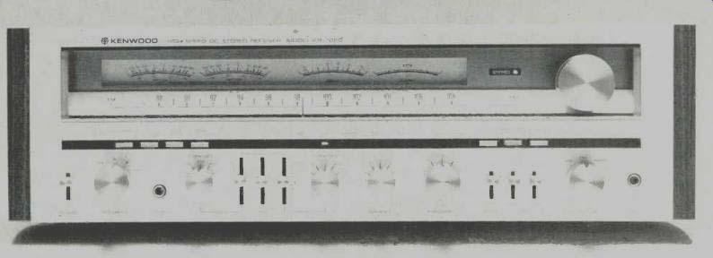
Much of the advanced amplifier and tuner technology which Kenwood has been emphasizing in their new "high speed" amplifiers and state-of-the-art separate tuners has been incorporated in this new receiver from Kenwood. So much, in fact, that one begins to wonder whether there is any longer any reason to opt for "separates" in any medium-high powered home audio system. In terms of control features, the Kenwood KR-7050 is amply endowed. The dial area has a pair of logarithmically calibrated power-output meters which can be read accurately from 0.01 watts to 160 watts referenced to 8-ohm loads plus the usual pair of signal-strength and center-of-channel tuning meters. All four meters, plus the stereo indicator light, are mounted above a linearly calibrated FM frequency scale and the usual compressed AM scale.
The lower frame of the dial area contains two groups of pushbuttons and a series of indicator lights that denote pro gram source selected. The pushbuttons at the left are a loudness switch, d.c.-a.c. coupling of the amplifier, a high-filter switch, and a tone defeat switch. Those at the right are for de-emphasis selection (25 or 75 microseconds), FM muting and i.f. bandwidth selection.
Controls along the bottom section of the panel include a power On-Off toggle switch, speaker selector switch, three tone control levers (bass, mid-range and treble), a pair of five-position selector switches which determine the turnover frequencies for the bass and treble controls (80 Hz, 140 Hz, 250 Hz, 450 Hz and 800 Hz for the bass; 800 Hz, 1.4 kHz, 2.5 kHz, 4.5 kHz or 8 kHz for the treble), balance control, master volume control, selector switch, toggle switches for mode, tape monitoring and tape dubbing, a mike input jack, and the usual stereo headphone jack.
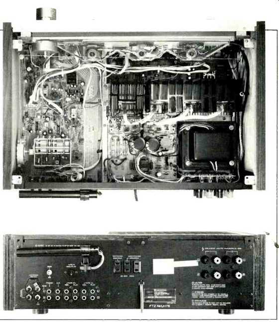
The rear panel of the KR-7050 is equipped with color-coded screw-terminals for connection of up to two pairs of speakers; the usual 300-ohm, 75-ohm (including a coaxial connector) and external AM antenna terminals; phono and high level input jacks; tape-in and tape-out jacks (enough for two tape decks); three convenience a.c. outlets (two unswitched, one switched), and the usual ferrite bar AM antenna, which can be pivoted down and away from the chassis surface for better AM reception.
Internal Construction and Circuit Highlights
The internal layout of the KR-7050 is a text-book model of thoughtful and intelligent engineering layout. Major circuit boards contain tuner circuitry, power amplifier circuitry, power supply circuitry, flat-amp/tone-control circuitry, and the FM front end, while secondary modules are used for sev eral of the complex switching functions. The phono preamp equalizer circuits are contained on the major tuner-section p.c. board.
A four-gang tuning capacitor is used in the FM front end which also utilizes a dual-gate MOS-FET r.f. amplifier plus separate bi-polar local oscillator and mixer stages. Multiple ceramic filters are used in the i.f. stages, with the filter configuration electronically switched depending upon whether the user selects wide- or narrow-band i.f. operation. A multi-purpose IC serves as an additional i.f. amplifier, limiter, and quadrature-detector circuit. The multiplex decoder circuitry is of the familiar phase-lock-loop type and includes a pilot-canceller circuit that eliminates the need for steep 19-kHz filtering at the audio output stages of the stereo decoder, thereby permitting better high-end response in the FM section.
Kenwood's d.c.-coupled "high speed" amplifier eliminates all coupling capacitors in the signal path from the AUX or high level inputs to the speaker output terminals. The phono preamp-equalizer uses FET input stages and a single-ended, push-pull output configuration. The d.c. sensing circuits operate relays to disconnect speakers in the event that any d.c. appears at the output terminals because of the directly coupled amplifier configuration. When the d.c. coupling is defeated by means of a front panel switch, frequencies below 18 Hz are attenuated at a rate of 6 dB per octave.
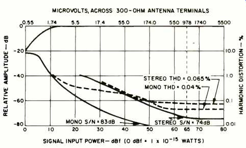
Fig. 1--Mono and stereo quieting and distortion characteristics, wide i.f.
setting.
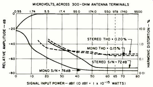
Fig. 2--Mono and stereo quieting and distortion characteristics, narrow
i.f. setting.
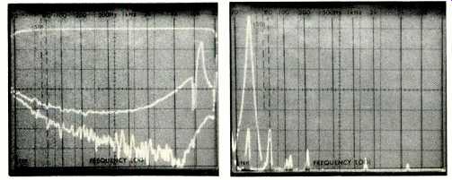
Fig. 3--Frequency response (upper trace) and separation vs. frequency for
narrow (middle trace) and wide (lower trace) i.f. bandwidth settings.
Fig. 4--Spectrum analysis of crosstalk for 5-kHz signal in stereo FM tuner section in wide bandwidth setting. (Sweep is linear at 5 kHz per division; vertical scale is 10 dB per division.)
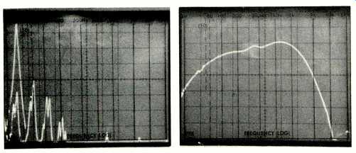
Fig. 5--As above but with bandwidth control in narrow position.
Fig. 6-AM frequency response.
FM Performance Measurements
As Kenwood rightly suggests in their literature, the tuner section of the KR-7050 is "like two tuners in one." That is, most of the major performance results differ when switching from "narrow" to "wide" i.f. modes. Signal conditions permitting, the "wide" setting offers best overall reception. As shown in Fig. 1, using this setting we measured a usable sensitivity in mono of 1.8 pV. The 50-dB quieting point required 3.0 uV (14.7 dBf) of signal strength in mono, as against 16.1 dBf claimed by Kenwood. The 50-dB quieting point in stereo was also better than claimed, with readings of only 34.7 dBf (30 pV). Signal-to-noise in mono measured 83 dB as claimed, decreasing to 74 dB for stereo. Distortion at 1 kHz in mono measured an incredibly low 0.04 percent at 1 kHz, increasing to 0.1 percent at 100 Hz and 0.077 percent at 6 kHz. In stereo, the 1-kHz THD reading was also amazingly low, 0.065 per cent for 1 kHz, 0.12 percent at 100 Hz and 0.11 percent at 6 kHz. Stereo switching threshold occurs at around 7 pV (22.1 dBf).
Our lab is now one of the few anywhere presently equipped with facilities for measuring CCIF IM distortion of tuners, as specified in the IHF-IEEE Tuner Measurement Standards. In this method, two tones (14 kHz and 15 kHz) are used as the modulating signal and the difference tone (1 kHz) which appears at the output is expressed as a percent age. For the Kenwood KR-7050, this IHF-IM reading was a mere 0.075 percent in mono and 0.12 percent in stereo, using the wideband i. f. mode. Many experts feel (and I agree) that this IHF-IM reading provides a better correlation between measurement and the sound quality that a tuner provides, and it is our intention to report results of these two-tone measurements in all future receiver and tuner test reports.
Figure 2 displays quieting and distortion characteristics of the tuner section when it is set to the narrow band position.
Under these circumstances, S/N in mono drops to 76 dB and to 72 dB in stereo. Mono THD increased to 0.15 percent at 1 kHz and read 0.085 percent at 100 Hz and 0.23 percent at 6 kHz. In the stereo mode, THD was 0.2 percent for a 1-kHz signal, increasing to 0.33 percent at 100 Hz and dropping to 0.18 percent at 6 kHz. Considering the fact that the selectivity is quite high with this setting (we measured an alternate channel selectivity of 85 dB, at 400 kHz away from the tuned-to frequency, while Kenwood provided specifications for a 300-kHz separation, probably because of European channel spacings), these readings are still quite impressive. IHF-IM readings in the narrow-band setting increased to 0.17 percent for mono and 0.30 percent for stereo.
The i.f. and spurious rejection ratios both measured in ex cess of 100 dB (the limits of our test equipment), while image rejection was 85 dB, a bit better than claimed. Muting thresh old was 9.0 NV (24.3 dBf). Capture ratio was exactly 1.0 dB as claimed, while AM suppression measured a bit less than claimed, but a still very adequate 60 dB.
Figure 3 is a composite photo of the frequency response and separation capabilities of the stereo FM section of the KR-7050. Response was down 0.5 dB at 30 Hz and was within 0.6 dB of flat at 15 kHz. Vertical scale in Figure 3 is 10 division. The lower trace represents the separation is some what degraded when the narrow i.f. setting must be used because of station crowding on the FM band in a given signal area. Key readings were 49 dB at 1 kHz, 44 dB at 100 Hz, and 45 dB for 10 kHz using the wide-band mode and 31 dB at 1 kHz, 28 dB at 100 Hz, and 30 dB at the 10 kHz using the narrow i.f. mode.
The nature and composition of the cross-talk in stereo was examined and is displayed in Figs. 4 and 5. In Fig. 4 (wide-band) the tall "spike" at the left of the sweep represents the "desired" left channel signal output, while the smaller spike observed at the right-channel output. As can be seen, the actual meter readings at the right channel output included fundamental cross-talk and second-order distortion, both of which were equal in amplitude of around 56 dB below the desired left-channel output. The test signal in this display is at 5 kHz and sweep is linear at 5 kHz per division from left to right.
In Fig. 5 we see the results of these same measurements using the narrow-band mode. In addition to observing reduced fundamental separation, we see the expected substantial increase in second-order distortion and third-order components in the right-channel output signal.
Figure 6 is a plot of the frequency response of the AM tuner section of the KR-7050. In this 'scope photo, log sweep was used (20 Hz to 20 kHz). Referenced to 1 kHz, response was down 10 dB at 60 Hz and 3.5 kHz. There is not much more that needs to be said about the AM section of this receiver.
Amplifier Measurements
While the FM tuner section of this receiver is quite impressive, the amplifier section really separates this receiver from others in its price and power class. In a word, it is superb! r Not that the static measurements on the bench are that superior to those obtained with other receivers; they are what we would have expected from any conservatively designed unit. It's the way the unit performs.
Maximum power at mid-frequencies, using 8-ohm loads, was 91.8 watts per channel as against the FTC power rating of 80 watts per channel. Using 4-ohm loads, the amp delivered 126 watts per channel for the same rated THD. At rated out put THD was a very low 0.005 percent at 1 kHz, rising to rated 0.02 percent at 20 Hz and 0.0084 percent at the high frequency extreme of the rated power band. SMPTE IM distortion was only 0.006 percent at rated output. Results of our power versus THD measurements are graphed in Fig. 7. Figure 8 is a plot of harmonic distortion at rated output versus frequency.
Power bandwidth for rated output at rated distortion extended from 20 Hz to 30 kHz. CCIF IM Distortion measured 0.0028 percent using 9-kHz and 10-kHz tones, 0.0039 percent with 14-kHz and 15-kHz tones, and 0.0054 percent with 19-kHz and 20-kHz tones. Damping factor measured 75 at 50 Hz, a bit lower than claimed.
Because Kenwood emphasizes the "high speed" performance of the amplifier section of this receiver, we made additional measurements of interest to verify these claims. Figure 9 displays input (upper trace) and output square waveforms for a 20-kHz input signal frequency. Clearly, the bandwidth of this amplifier is very wide. We attempted to move up in frequency to find a point at which the rise of the output waveform and its decay might begin to show some tilt only to find that when such tilt was evidenced, it was present in our input signal display as well, indicating that the 'scope in use was not equal to the task (it has a useful bandwidth of 500 kHz). Slew factor, measured per the new IHF standards, was far in excess of 5.
Perhaps even more impressive was the square-wave shape at the output of the amplifier as shown in Fig. 10. The frequency, in this instance was not 100 Hz or 20 Hz, but a sub-audible 10 Hz, and yet there was absolutely no "tilt" to the flat horizontal portions of the waveshapes. To further explore the bandwidth (or "speed" to use Kenwood's term) of this amplifier, we reapplied a 20-kHz square wave signal to the amp (via the AUX input, incidentally) and magnified the 'scope display, superimposing input waveform above output waveform. We increased the level until the peak-to-peak voltage across the output terminals was equal to the peak-to-peak voltage of a sine-wave equivalent to rated output. As can be seen by a close examination of Fig. 11, we are only just beginning to see a slight (but equal) time delay in the rise and fall of the output waveform compared with the in put signal.
RIAA equalization of the phono preamp circuitry was ac curate to within ±0.2 dB as claimed, from 20 Hz to 20 kHz.
Phono input sensitivity, per the new IHF standards, was 0.25 mV for 1-watt output, and phono overload for a 1-kHz signal measured 220 millivolts. Signal to noise in phono, again using the new IHF Standard references of 5-mV input and 1-watt output was a very high 79 dB ("A" weighted). For the high level inputs, sensitivity for 1-watt output was 22 mV, and signal to noise, referred to 0.5-volts input and 1-watt output, measured 78 dB, "A" weighted.
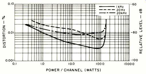
Fig. 7--Harmonic distortion vs. power output.
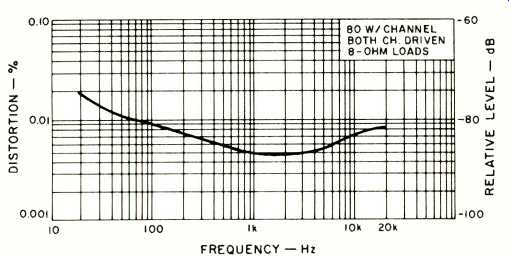
Fig. 8--Harmonic distortion vs. frequency.
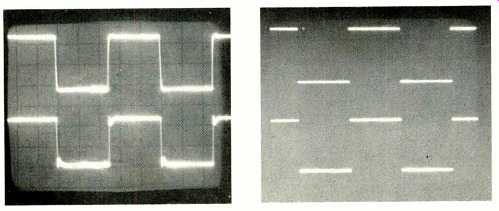
Fig. 9--Response to 20-kHz square wave. (Upper trace is input.). Fig. 10--
Response to 10-Hz square wave. (Upper trace is input.)
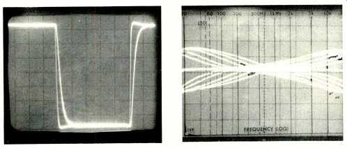
Fig. 11--Response to 20-kHz square wave of rated output level superimposed
on input wave form.
Fig.
12--Bass and treble control response curves taken at all available turnover
settings with maximum boost and cut.
Figure 12 shows the multiple response traces obtained with each of the five bass and treble turnover positions with these controls set alternately at maximum boost and cut settings.
The availability of so many different turnover points adds a great degree of flexibility to these tone controls, which are augmented by the additional mid-range tone control, whose maximum range of boost and cut is displayed in Fig, 13. Also shown in Fig. 13 is the response of the high-cut filter which, though sloped at a moderate 6 dB per octave, has a turnover point that is high enough in frequency so as not to interfere severely with musical material being reproduced when it has to be used.
The action of the loudness compensation circuit of the Kenwood KR-7050 is shown, for various incremental settings of the master volume control, in Fig. 14. Note that Kenwood has wisely, in our opinion, refrained from incorporating treble boost in their loudness circuit. Many manufacturers mistakenly incorporate such boost in typical loudness compensation circuits because the familiar Fletcher-Munson curves suggest that human hearing falls off at the high end.
Indeed it does, but the degree of roll-off in hearing is almost entirely independent of listening levels (unlike the bass fall off which increases at progressively lower listening levels) and therefore no loudness compensation needs to be added in the treble range.
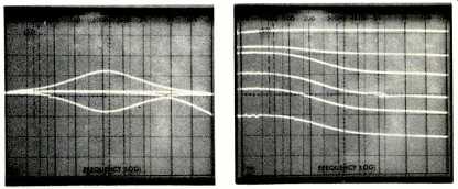
Fig. 13--Response of mid-range control and high-cut filter. Fig. 14--Loudness
control characteristics.
Subjective Evaluations
We were so impressed with the performance of the Kenwood amplifier circuitry of the KR-7050 that we thought it might be best to invite a few additional qualified listeners to join us in our listening tests. Since, to our ears, we could not distinguish between the tight, clean, and utterly transparent sound of some of the best separates we normally use for reference listening purposes in our lab and the sound of the KR-7050, we decided to conduct the auditions with the receiver hidden from view.
A recent outstanding digitally mastered disc, Telarc's DG-10040, Malcolm Frager Plays Chopin (he uses a Bosendorfer Imperial concert grand piano) was played first. This recording makes unusual demands upon the entire audio reproduction system, from cartridge to speakers, with transients, percussive, and bass piano sounds that must be heard to be believed. All three of my itinerant listeners guessed that we were listening to a high-end, high priced separate amplifier, a "straight wire with gain" control-less preamp, and a top-grade cartridge. They were right about the cartridge, but were all astounded when the Kenwood receiver was unveiled. Other recordings, ranging from direct-to-disc rock to orchestral works, were also auditioned, although by this time the nature of the equipment had been disclosed.
Here is one instance in which the wide-band measurements made on the bench correlated nicely with the subjective results obtained during actual listening tests. If Kenwood prefers to talk about high-speed while others talk about low TIM, high slew rate and wide bandwidth, I have no quarrel with them. Just so long as they keep on making receivers that sound this good!
-Leonard Feldman
(Audio magazine, Jul. 1979)
Also see:
Kenwood KR-6340 "Two-Four" Receiver (Equip. Profile, Dec. 1973)
Kenwood Model KA-3500 Integrated Stereo Amplifier (Equip. Profile; Dec. 1976)
Kenwood KP-5022 Turntable (Sept. 1975)
Kenwood KX-660HX Cassette Deck (April 1988)
= = = =