
Manufacturer's Specifications
Frequency Response: 20 Hz to 50 kHz, ±0.25 dB.
Input Sensitivity: MC phono, 250 rms at 1 kHz; MM phono, 2 mV rms at 1 kHz; all others, 110 mV rms.
Input Impedance: MC and MM phono, 50 kilohms, 100 pF; all others, 25 kilohms.
Input Overload: MC phono, 120 mV rms at 1 kHz; MM phono, 1.2 V rms at 1 kHz; all others, 50 V.
Output Level: Main, rated 1.4 V rms, max. 27 V rms, into 10 kilohms or higher; tape, 110 mV.
Output Impedance: Main, 470 ohms; tape, 2 kilohms.
Distortion (TIM and IM): Phono, 0.005%, 20 Hz to 20 kHz at rated sensitivity, 0.01% at 0.9-V input at 1 kHz; all others, less than 0.0009%, 20 Hz to 20 kHz at rated sensitivity, 0.008% at 26-V output at 1 kHz into 10 kilohms or higher.
Noise (Inputs Loaded): MM pho no, -86 dB re: 10-mV input, -78 dB (-86 dBA) re: 2 'TA/ at 1-kHz in; MC phono,- 64 dB (- 72 dBA) re: 250 uV; all others,-104 dB (-108 dBA).
Output Stage Phase Accuracy: ± 1°, 20 Hz to 20 kHz.
Channel Separation: 70 dB, 20 Hz to 20 kHz.
Dimensions: 19 in. (48.3 cm) W x 12.5 in. (31.8 cm) D x 2.1 in. (5.3 cm) H.
Weight: 11 lbs. (5 kg).
Price: $1,299.00.
Company Address: Techport Ltd., 875 Merrick Ave., Westbury, N.Y. 11590.
The Perreaux SM2 is, I believe, the first preamp to be sold in the U.S. from this "down-under" company in New Zealand. It is of the straight-line, no-tone-control, no-frills school.
A number of interesting circuit ideas are incorporated into this preamp: The phono-stage power supplies deliver un usually high voltages (for a solid-state) design :o provide high input acceptance; phono-circuit gain is switchable to allow use of MM or MC cartridges, and a shielded, toroidal power transformer allows MC gain without hum, even though the transformer is in the preamp chassis. The circuit also uses polypropylene and polycarbonate capacitors in the signal path, unregulated power supplies (but with very large filter capacitors), and MOS-FET transistors in the line-amplifier output stage.
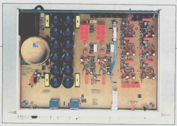
Front-panel controls include, from left to right, a pushbutton on-off power switch, balance and volume knobs, an input selector, and a tape-monitor toggle switch. On the rear panel are gold-plated connectors for inputs and outputs, a phono gain switch, and a three-wire a.c. power cord.
All of the circuitry, including the power transformer, is on one large p.c. board taking up the entire internal area of the chassis. The ground plane and interconnecting traces are 24-karat gold plated to prevent corrosion, reduce resistance, and provide better r.f. shielding. Parts quality and construction appear to be first-rate.
Circuit Description
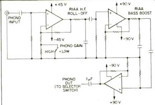
Fig. 1-Phono-circuit block diagram.
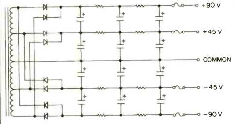
Fig. 2-Power-supply configuration. Four diodes at center form one bridge rectifier,
top and bottom diode pairs form a second bridge rectifier. Each capacitor is
4,700 uf, 50 V.
Since a schematic was not provided with this unit, exact circuit details could not be determined without lengthy circuit tracing.
The phono amplifier appears to be a three-stage affair. The first stage is where the gain is changed for MM or MC use. Gain is most likely changed by altering effective emitter resistance or shunt feedback resistance, as noise is lower in the high-gain position. The high-frequency portion of the RIAA equalization is done by a passive RC network at the output of this first stage. The second stage, like the other two stages, is flat. The bass boost portion of the RIAA curve is accomplished by a passive RC network at the output of the second stage. The third stage acts as a buffer and has a small voltage gain.
These three amplifier blocks have similar circuitry, consisting of five NPN and PNP bipolar transistors in a complementary configuration.
Power-supply voltages to the phono stages are ±45 V to the first stage and ±90 V to the second and third stages. A block diagram of the phono preamp is shown in Fig. 1.
The output amplifiers are a combination of NPN and PNP bipolar transistors feeding a complementary pair of MOS FET devices for the outputs.
These MOS-FETs are run at much lower current than in the Spectral DMC-10 (Audio, September 1983), about 0.4 mA. Further, there is one N and one P device, whereas the Spectral used two P devices in parallel to more closely match the N device. Why such a low quiescent current is used, I can't fathom. One can see crossover distortion a high frequencies, even though the amount of distortion is very low. Turning up the bias pots gets rid of this distortion without over-dissipating the MOS-FETs. Power supply voltage for the output amplifier is ±45 V.
The output of this line amplifier is muted by relay contacts which short the main outputs to ground against series 470 ohm resistors. This is in contrast to the usual connection, which puts the contacts in series with the output signal.
Perreaux claims, correctly, that their configuration gets the contacts out of the signal path. The time delay of the relay control circuit is short, about 2 S, as the circuitry settles down about that quickly.
The power supply in this preamp is unusual in that it is unregulated and also has an interesting topology. The equivalent amount of filtering is tremendous due to the number and large size of the filter capacitors. A schematic of this circuit is shown in Fig. 2.
Measurements
As has been my custom of late, circuit gains and sensitivities were measured first and are presented in Table I. Next, phono input noise was measured for different source impedances, bandwidths, and gain settings. This data is enumerated in Table II. Noise values are on the high side of what can be achieved with solid-state circuitry. IHF signal to-noise ratios for the phono and line sections are listed in Table III.
Phono total harmonic distortion plus noise was measured at 5-V output with my normal load (distortion analyzer plus 'scope and connecting leads; 90 kilohms and 250 pF) and with the IHF load (10 kilohms and 1,000 pF); it was less than 0.01% from 20 Hz to 20 kHz with either load. Distortion at high frequencies starts to rise above 5-V output, which is due to the phono input amplifier reaching its maximum input acceptance.
Phono overload versus frequency, gain, and loading at tape output was measured (Table IV). In all cases, the limit is some aberration on the output waveform as observed visually on a 'scope. In a perfect RIAA preamp section, the shape of the overload versus frequency curve would be the inverse of the RIAA curve itself, and the maximum output level would be constant with frequency. This is not the case here: Once the input level reaches about 1 V for low gain and about 0.16 V for high gain at 1 kHz, the output level attainable begins to drop. This is caused by the input amplifier in the phono preamp section going into clipping, preventing any further increase in input level without distortion. However, let's face it: 1-V input at 1 kHz is indeed a high input level acceptance! It's unlikely that any cartridge will overload the phono section of the SM2. A worst-case scenario-a Shure M44 cartridge puts out 10 mV at standard level at 1 kHz. Let there be 20-dB peaks over the whole frequency range. Then, 10 mV becomes 100 mV at 1 kHz and 1 V at 20 kHz. This would just tick the maximum input acceptance of the SM2. However, 20-dB peaks in the range of 10 to 20 kHz are not very likely because of cutting limitations.
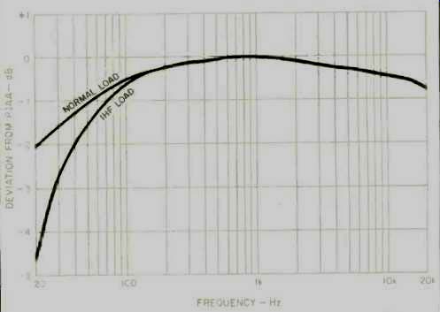
Fig. 3-RIAA equalization error for normal load (90 kilohms and 250 pF) and
IHF load (10 kilohms and 100 pF). Shown for right channel, measured at tape
output.
Phono equalization error versus frequency is shown in Fig. 3. The curves are for low gain and the right channel, which was slightly worse than the left. In the high-gain mode, the errors were essentially the same above 500 Hz, but 20 Hz was down about 1 dB more with IHF loading. The low-end roll-off in this unit is excessive, in my opinion, as I have found that (all other things being equal) extending the low-frequency bandwidth in a phono equalizer or any flat amplifier generally produces better sound in the midrange in addition to producing better bass. This general tendency of restricted I.f. bandwidth throughout the whole circuit allows it to settle down so quickly upon turn-on. 'Scope patterns of the phono circuit response to square waves are shown in Fig. 4. Figure 5 shows the effect of increasing drive level into the phono section at normal gain. The asymmetry is caused by the phono first stage clipping asymmetrically.
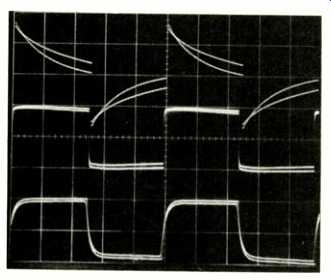
Fig. 4-Phono-preamp square-wave response: 40 Hz (top), 1 kHz (middle), and 10
kHz (bottom). Dual traces show effects of normal and IHF loads. (Vertical scale:
1 V/cm; horizontal, sweep frequencies adjusted for constant trace width at
each frequency.)
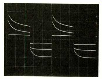
Fig. 5--Effect of increased drive level into phono section, showing 1 kHz at
three different signal levels. (Vertical scale: 2 V/cm; horizontal, 200 µS/cm.)
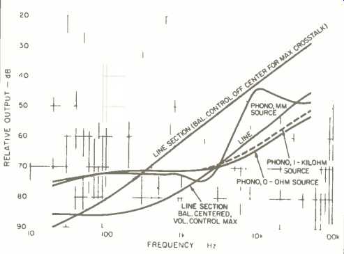
Fig. 6-Crosstalk vs. frequency for line and phono sections. Note increase in
line-section crosstalk when balance control is moved towards driven channel.
(The same effect was seen with balance control centered and volume control
lowered 6 dB from maximum.) Also note phono crosstalk increase at high frequencies
with IHF MM source.
Interchannel phono crosstalk versus frequency and source impedance is shown in Fig. 6. Crosstalk increased at high frequencies with the IHF MM source, though not to the same extent as in the Audio Research SP-10 (Audio, June 1984). Crosstalk in the high-gain position was about the same as shown for low gain. Crosstalk was in phase with the driving source, using square-wave excitation. The phono preamplifier's input impedance was representable to a satisfactory degree of accuracy by a parallel combination of 51 kilohms and 125 pF.
The line amplifier was measured for THD plus noise, which was found to be less than 0.01% from 20 Hz to 20 kHz, at 10-V output or less with normal or IHF loads.
When crosstalk versus frequency was measured for the line section, some anomalies showed up. With the volume control fully clockwise and the balance centered, everything was quite good. Moving the balance control toward the driven channel increased crosstalk substantially at high frequencies. With the balance again centered, but with the volume control down 6 dB, a similar effect occurred. These results are also plotted in Fig. 6. Crosstalk for the line section was in phase.
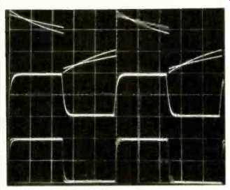
Fig. 7--Line-amp square-wave response: 20 Hz (top) 20 kHz wit, volume control
set 8.5 dB below maximum (middle), and 20 kHz with volume control fully clockwise
(bottom). Dual traces show effects of normal and IHF loads. (Vertical scale:
2 V/cm for top and middle curves, 5 V/cm for bottom; horizontal, sweep frequencies
adjusted for constant trace width at each frequency.)
'Scope pictures for the responses to square waves are shown in Fig. 7. Rise-time and slew rate for the output amplifier were measured; for a 50-V peak-to-peak output signal and IHF load, the output was definitely slewing. The negative-going transition was -40 V/uS or -20 V/uS, and the positive-going transition was 40 V/1.6 uS or 25 V/µS. These figures can be interpreted as large-signal rise and fall times, since 40 V out of 50 V is 80% (90% - 10%) of the total amplitude of the step transition. For the normal load, things speeded up to a positive transition of 40 V/RS and slowed to a negative transition of 23.5 V/uS. Small-signal linear rise and fall times at 10 V peak-to-peak were 1 RS for normal load and 1.3 RS for the IHF load. With the volume control down 6 dB from maximum, the rise and fall times lengthened to 2 RS for normal load and 2.5 RS for the IHF load.
Input impedance of the line section, with volume at maxi mum and balance centered, turned out to be 22 kilohms in parallel with 180 pF. The preamp's output impedance was about 470 ohms.
Use and Listening Tests
Functionally, the SM2 works perfectly, with no operational glitches. Turn-on with gain advanced on phono produces no thumps; turn-off is also quiet. Switching my turntable on and off with gain at playing level on phono produces a mild pop. On this basis of rating r.f.-interference susceptibility on phono input, the SM2 rates as good.
A note about the three-wire power cord of the SM2 (or any other preamp with such a cord). The third wire connects to the chassis and signal ground. If other pieces of equipment in a hi-fi system have three-wire a.c. cords, which most power amps have, a potential ground loop between the chassis exists which could cause hum and sonic degradation. I recommend third-wire grounding to the a.c. outlet at only one piece of equipment-usually the power amp. Use three- to two-wire, ground-lifter plug adaptors on any other three-wire power cord in the system.
Equipment used to evaluate the SM2 included an Infinity air-bearing turntable and arm; a Koetsu EMC-18 cartridge; Fidelity Research XF-1 Type M moving-coil step-up trans former (used only with a reference tube preamplifier); Marantz Model 9, Dyna Stereo 35, Mark Levinson ML-9 and Audio Research D-70 power amplifiers, plus the Audio Re search SP-10 preamp and GC/BHK developmental tube preamp (the latter two as references). Speakers included the Infinity RS2 and RS2a and a hybrid system with a cone woofer array and Infinity EMIM midrange and EMIT tweeter drivers.
When the SM2 was first received for evaluation, it was listened to on the RS2 speakers with either Marantz 9s or the Audio Research D-70. My initial reaction at that time was not very favorable. My listening notes indicated flat, nondimensional sound that seemed to alter the harmonic structure of instruments and voices, making them sound somewhat unreal. I then loaned the unit to a friend who uses the hybrid cone/EMIM/EMIT speaker system. He is a very perceptive listener, and thought the SM2 preamp was generally okay. A later substitution of a conrad-johnson PV-2A made his system sound more spacious and musically natural.
Recent listening with the SM2 in my system, using the RS2a speakers, has allowed me to finally quantify this preamp. The combination of the SM2 and the Dyna Stereo 35 or Levinson ML-9 yields a very smooth, listenable sound.
I would characterize the sound of the SM2 as smooth and easy but with deficiencies in replicating space and musical excitement. By comparison, when I use the SP-10 or my reference tube preamp with either of the above-mentioned power amps, resolution, spaciousness and excitement re turn to my system's reproduction. If I were to compare the SM2 to the Spectral DMC-10, which is reasonable. I would prefer the Spectral preamplifier, as it is more open and spacious sounding.
A few last observations: Sound through the SM2 was a little better with the phono gain at low. Perceived S/N was okay using the Koetsu this way, and it was obviously better in the high-gain mode.
The above are substantially my personal opinions on the sound of the Perreaux SM2. As with any well-made piece of gear recommend that potential buyers listen to this preamplifier with potential combinations of equipment they are interested in, to form their own personal opinions.
-Bascom H. King
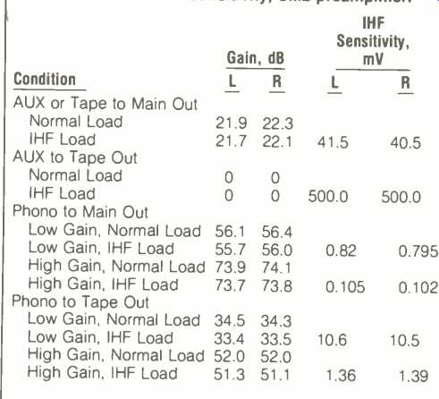
Table I-Gain and IHF sensitivity, SM2 preamplifier.
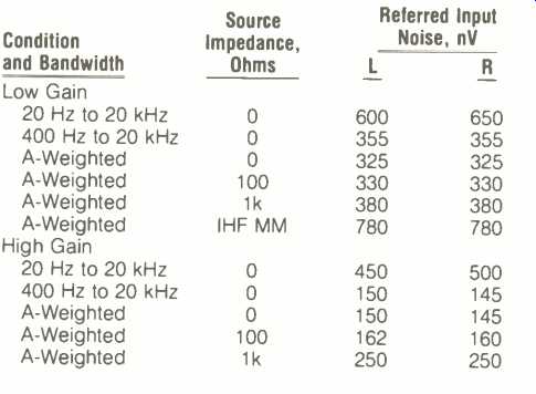
Table II-Phono noise, referred to input.

Table III-IHF signal-to-noise ratios, phono and AUX inputs.
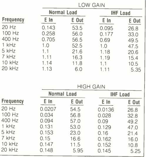
Table IV-Phono overload (in V rms) vs. frequency, loading and gain.
(Audio magazine, Jul. 1984 )
Also see:
Perreaux Audio (ad, Nov. 1984)
= = = =