SINGULAR IDEAS
by KEN POHLMANN
Okay, I'm serving notice: I'm sick and tired of hearing snide comments about single-beam pickups in CD players. Sure, in a world beset by problems (acid rain, holes in the ozone layer, rain-forest defoliation, mutually assured destruction, fast-food croissants) it might not seem like much, but a person has to put his or her foot down somewhere. And I'm putting mine down on single-beam pickups.
Well, not on the pickups themselves, but on the widespread belief that three-beam pickups must be better than single-beam designs-apparently because, well, they have two more beams. Friends, it ain't necessarily so.
Let's review the principles behind a hypothetical, generic, single-beam design; I think you'll agree that the method is both clever and elegant, and a great way to read the 3 billion or so pits precisely arranged on the spiral track of a Compact Disc.
As I've discussed in previous columns, the optical pickup in a CD player must focus on, track, and read that data spiral without touching the disc itself, using only light to achieve its ends. The objects of concern on the disc are the pits, which carry the encoded data. Via their height and reflectivity, they modulate the intensity of the light beam shining on the disc surface, thus allowing the data to be recovered.
To achieve sharp focus on the data surface and to properly achieve intensity modulation from the pit height, it is necessary to use a laser as the light source. A laser light is monochromatic (composed of a single frequency) and coherent in phase. As we'll see, the latter is vital in implementing phase cancellation in the reflected beam, and hence in reading disc data.

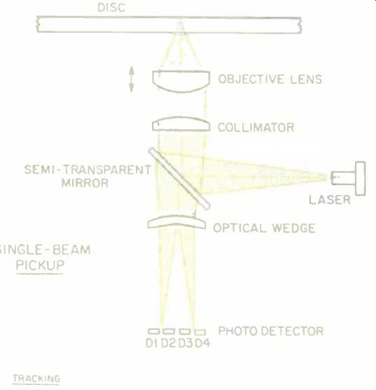
Fig. 1--Layout of a single-beam pickup for a CD player.

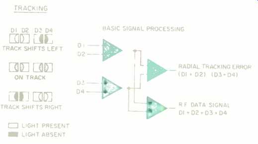
Fig. 2--Tracking control system for a single-beam pickup.

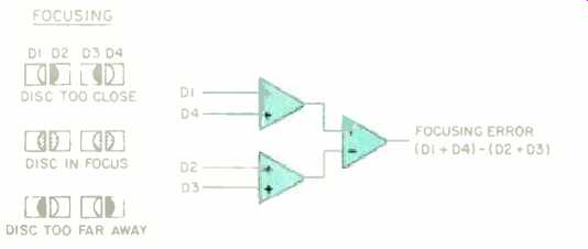
Fig. 3--Focus control system for a single-beam pickup.
The optical components of a one beam design are shown in Fig. 1, along with the photodiode array used to generate tracking and focusing signals and to read the data signal. A laser diode is used to generate the laser light. A monitor diode (not shown) is placed next to the laser diode to control power to the laser; it compensates for temperature changes and prevents thermal runaway. The monitor diode conducts current in proportion to the laser's light output. In other words, it stabilizes the semiconductor laser's output.
The next part of the optical system, a semi-transparent mirror, angles the laser light toward the disc surface. A collimator lens follows the mirror (or, in some designs, precedes it). Because the laser diode is placed at the focal point of the collimator lens, the lens makes the divergent light rays parallel.
The final piece of optics in the path to the disc is the objective lens; it is used to focus the beam on the disc data surface, taking into account the refractive index of the polycarbonate substrate. The objective lens focuses the laser beam into a convergent cone of light whose main spot is about 800 micrometers in diameter on the outer surface of the disc's transparent poly carbonate substrate. The refractive index of the polycarbonate substrate is 1.55 and its thickness about 1.2 millimeters. so the spot is narrowed to 1.7 micrometers at the reflective surface--slightly wider than the pit width of 0.5 micrometer, and comparable in width to the wavelength of the light itself.
The data encoded on the disc now determines the fate of the laser light.
When the spot strikes land (the smooth intervals between pits), the light is almost totally reflected. When it strikes a pit (seen as a bump by the laser), whose depth in the transparent layer is about one-fourth the laser light's wavelength, destructive interference and diffraction cause less light to be reflected. Hence the reflected light reads the pits as they fly past.
The intensity-modulated light beam returns through the objective lens and the collimator lens to strike the angled mirror surface. It passes through the mirror and then through a wedge lens.
The wedge lens splits the beam into two beams, which are adjusted to strike an array of four horizontally arranged photodiodes. The outputs of all the photodiodes (D1, D2, D3, and D4) are summed to provide the data signal, which is demodulated to yield audio data and control signals.
Ironically, reading data is the (relatively) easy part of a pickup's job. The tasks of keeping the pickup in focus and on track take a lot more work. To maintain tracking and focus within tolerance, a servo system is required. A servo is an electromechanical device, similar to a motor, in which an input electrical signal controls the mechanical motion. In a CD player, the servo's job is twofold: To move the objective lens along the optical axis in response to vertical disc motion, thus maintaining focus, and to move the lens perpendicularly to the optical axis to maintain tracking.
Consider the problem of tracking: On a CD, the track pitch--the distance between adjacent laps of the pit spiral--is 1.6 micrometers; that is too fine a tolerance for any mechanical tracking system, if the system is to be cost effective. What is required is an automatic tracking system which uses the laser light itself to keep the pickup's data beam on track.
In a single-beam design, the diodes generate error signals for auto tracking. When the laser spot strikes the center of the pit track, a symmetrical beam is reflected. If the laser beam wanders from the pit track, interference creates asymmetry in the beam, resulting in an intensity difference between the two split beams, as shown in Fig. 2. As the beam moves off-track, one side of the beam encounters more reflective land; as a result, less interference occurs on that side of the beam, and reflected light is more intense there. Thus, the split beam derived from that side is more intense, and the photodiode's output is greater. Either photodiode pair D1/D2 or D3/D4 generates a greater signal from the increased laser light. The difference between the pairs produces an error signal to keep the pickup on track.
Aging or soiling of the pickup could cause the reflected beam to become increasingly asymmetrical. This asymmetry would generate a constant offset in the primary tracking-correction signal, causing the pickup to remain slightly off-track. To prevent this from occurring, a second tracking-correction signal is generated. A low-frequency (e.g., 600-Hz) alternating voltage is applied to the coil that controls the tracking. The output signal from the four photodiodes is thus modulated by the alternating tracking-correction signal. As the pickup wanders off-track, a deviation in the tracking-correction signal occurs in the modulated signal.
When the modulated signal is rectified, a drift-free tracking-correction signal is produced. This is used to correct the primary tracking signal with a DC voltage. The data signal from the four photodiodes is thus always returned to its maximum value.
The other problem is maintaining focus: Disc warpage and other irregularities can cause vertical deviations in the disc data surface; these can place the data out of the pickup's depth of focus. If the pickup didn't compensate, it would lose the ability to distinguish the phase difference between pit height and land. Tolerance is approximately ±0.5 micrometer.
Auto focusing is accomplished by the four photodiodes. As shown in Fig. 3, when correct focus is achieved, two sharp images are located between photodiode pairs. When focus varies, the focal point of the system is shifted, and the split beams draw closer together (when the disc is too far away) or farther apart (when the disc is too near). The difference between diode pairs D1/D3 and D2/D4 forms a focus error signal, (D1 + D4) (D2 + D3), which is used to maintain the focus of the servo-driven objective lens. Of course, in practice, the four photodiodes must simultaneously perform all three tasks of data reading, tracking, and focusing.
Although single-beam pickups can be mounted on a linear sled (which is mandatory for three-beam pickup designs), most are mounted on a pivoting arm which describes a radial arc across the surface carrying the data. A coil and permanent magnet are mounted around the pivot point of the arm.
When the coil is energized, the pickup may be positioned anywhere on the pit track and its position corrected by the auto-tracking system. The objective lens is provided with a coil and a permanent magnet for displacement in the direction of the optical axis, for purposes of auto focusing.
Whatever the particulars, it should be clear that single-beam pickups are relatively simple mechanisms. And that is precisely their advantage over the more complex three-beam designs. In the final analysis, both perform the same function, and in terms of traditional specifications such as frequency response and channel separation, there is no sonic difference between the two. However, there are engineering advantages which may favor the signal-beam pickup. The optics in a three-beam design are inherently more complicated; there are at least five components (objective lens, collimator, diffraction grating, cylindrical lens, and beam splitter) compared to the four components in a single-beam design (objective lens, collimator, optical wedge, and semi-transparent mirror). In addition, the three-beam design requires several critical adjustments, including secondary-beam and diffraction-grating alignment (the two extra beams are used for tracking), as opposed to the single adjustment of the photodiode assembly's horizontal position in a single-beam design.
A three-beam design is also more complex from a mechanical viewpoint.
As noted, a single-beam design can be mounted on a single pivoted arm, which describes an arc across the disc surface; since there is only one moving part, wear is minimal and reliability is high. A three-beam design requires a linear sled mechanism because the tracking beams must stay in a fixed position relative to the pit track. For all these reasons, it can be argued that single-beam designs are more robust and may provide more reliable data readout with fewer tracking errors, especially over the long run. Still, three beam designs predominate, probably because manufacturers believe con sumers think them superior.
Ultimately, pickup performance must be evaluated on a player-by-player basis, and it is important not to let prejudice cloud that evaluation. As consumers become more knowledgeable, single-beam pickups may stage a comeback. In fact, there are signs that this is already happening: At least one major manufacturer has decided to switch back to the single-beam camp. Now, about that perplexing fast-food croissant problem....
(adapted from Audio magazine, Jul. 1988)
= = = =