
Manufacturer's Specifications:
Continuous Power Output: Stereo, 220 watts per channel into 8 ohms, 420 watts into 4 ohms, 640 watts into 2 ohms, 730 watts into 1 ohm; bridged mono, 600 watts into 8 ohms, 700 watts into 4 ohms.
Peak Power Output Per Channel: Stereo, 310 watts per channel into 8 ohms, 590 watts into 4 ohms, 900 watts into 2 ohms, 1,000 watts into 1 ohm; bridged mono, 840 watts into 8 ohms, 980 watts into 4 ohms.
Peak Output Current: 50 amperes into 0.1 ohm, for 1-kHz signal switched on for 20 mS and off for 480 mS. Voltage Gain: Stereo, 29 dB; bridged mono, 35 dB.
Frequency Response: 0.2 Hz to 200 kHz into 8 ohms, 0.2 Hz to 32 kHz into 8 ohms plus 8µF.
Rise-Time: 0.6 µS into 8 ohms, 5.0 uS into 8 ohms plus 8 uF.
THD Into 8-Ohm Load: Stereo, 0.5% at 200 watts out, 0.1% at 10 watts, 0.05% at 1 watt; bridged mono, 0.5% at 200 watts, 0.10% at 10 watts, 0.08% at 1 watt.
S/N Ratio: 84 dB below 1 watt out, measured from 400 Hz to 80 kHz, with 8-ohm load.
Input Impedance: 100 kilohms plus 100 pF.
Output Impedance: 0.12 ohm, typical.
Damping Factor: 60, re: 8 ohms.
Signal Polarity: Noninverting.
Power Consumption: 260 watts at idle.
Dimensions: 19 in. W x 6.7 in. H x 19 in. D (48.3 cm x 17 cm x 48.3 cm).
Weight: 69 lbs. (31.3 kg).
Price: $2,795.
Company Address: 2610 Commerce Dr., Vista, Cal. 92083.

The SA-220 is the larger of two hybrid power amps made by Counterpoint. The smaller unit is rated at 100 watts per channel into 8 ohms; the SA-220, reviewed here, is rated at 220 watts per channel into 8-ohm loads. Counterpoint also makes an output-transformerless, output-capacitorless, all tube power amp and a number of tube preamps. The company's products have been well reviewed and accepted by the audiophile community.
Rather than using a solid-state front-end and tube output stage with output transformer, as some hybrid amps do, the SA-220 is of the type that uses a tube front-end and a solid-state, transformerless output stage, in this case utilizing complementary MOS-FET output devices. Excellent sound can be produced from either approach when the proper design techniques are employed.
The SA-220's front panel has a rocker "Power" switch at the lower right. An LED indicator above and to the right, near the manufacturer's logo, glows red when the amp is first turned on and then turns green after a suitable but long delay of about 90 S, signifying that the amp is ready.
On the rear panel are a pair of Tiffany input phono connectors, a pair of five-way binding posts for speaker connections, and the a.c. power cord. An a.c. line fuse, positive and negative power-supply fuses for each channel, and speaker fuses are inside the unit.
Checking out the interior of the SA-220 reveals that the front third of the space is taken up by an appropriately large and beefy power transformer; two pairs of 25,000-µF, 75-V filter capacitors, and two bridge rectifiers. The rest of the space is occupied by a large double-sided p.c. board on which the input circuit tubes and most of the amplifier circuit parts are mounted. Two more circuit boards, one per channel, hold the protection circuitry. These boards are mounted on the insides of the heat-sinks and connect the protection circuitry directly to the output devices.
Physically, the SA-220 is a reasonably sized package for what it contains, and it weighs in at nearly 70 pounds. The main chassis is made up of one piece that is bent up and spot-welded together to form the bottom, the front subpanel, the front third of the sides, and the rear panel. This chassis is copper-plated, which Counterpoint feels makes the unit sound better. Making up the rear two-thirds of the sides are the extruded heat-sinks for the output stage.
The front panel is rack width (19 inches) and 6.7 inches in height. The panel's thickness is about 3/16 inch. Another piece, 2 1/2 x 19 x 1/4 inches, with tapered top and bottom edges, is bolted across the front panel, about halfway up, to create the distinctive front-panel appearance of Counterpoint components. Finally, a vented top cover completes the enclosure. This top cover is attached to the main chassis with numerous 6-32 screws threaded into Pemm nuts mounted on a half-inch ledge. This ledge goes all the way around the top of the chassis, except where the heat-sinks are.
I have had the opportunity to compare Counterpoint's earlier SA-20 with the newer SA-220 reviewed here, and I find that the later model's metalwork is quite an improvement in terms of general sophistication and elegance. The SA-220 reviewed had a black anodized front panel; a brushed silver anodized finish is also available on all Counterpoint products.
Circuit Description
Signal input is directly coupled through a series resistor into the grid of the first-stage tube. A resistor to ground across the signal input sets the input impedance at 100 kilohms. The first stage is operated as a common-cathode amplifier, with the output signal taken at its plate. This output is capacitor-coupled to the second stage, which is also operated as a common-cathode amplifier. The plate output of the second stage is direct-coupled to a third tube acting in common-plate or cathode-follower mode. A fourth tube is connected as a current source to the cathode follower.
The circuitry just described is implemented with two 6DJ8 dual triodes. Each of the three stages' plate circuits is decoupled from the power supply with a series resistor and a shunt capacitance made up from paralleled electrolytic and film capacitors. A proprietary feedback loop encompasses this entire front-end tube circuit. The net result of all this tube circuitry is to provide the amplifier's voltage gain as well as a low output impedance to drive the output stage and, being tubes, to help produce the sonic wonder that the whole design is to exhibit! In addition to the two 6DJ8s per channel, half of another dual triode is engaged when the amplifier is in bridged mode. The fifth tube acts as a unity-gain phase inverter to reverse the polarity of the right channel. This inverter circuit is completely out of the signal path when the SA-220 is in stereo mode.
The output stage is composed of four N-channel and four P-channel MOS-FET power devices configured in a complementary source-follower arrangement, the four N-channel and P-channel devices being wired in parallel in two groups for increased power handling capacity. The devices employed are International Rectifier TO-3 metal-cased units, which are being used increasingly in new designs because their reliability and characteristics have improved. The tube stages' output cathode follower is connected to the output stage via separate coupling capacitors to the gate circuits of the Nand P-channel devices. Constant-current-fed zener diodes provide stable positive and negative voltage sources to feed a resistive voltage-divider circuit connected to the MOS-FET gates. This divider feeds the bias-spreading regulator and allows adjustment of the amplifier output's d.c. offset to 0 V. Contrary to popular belief, not all MOS-FET output stages have negative temperature coefficients at the idling currents typically used in MOS-FET power amplifiers. The Hitachi MOS-FETs found in many early and current designs do cross over from a positive to a negative temperature coefficient at a fairly low current, with the coefficient being negative at the idling currents typically used. In contrast, most modern devices made by International Rectifier and other companies have a positive temperature coefficient up to several amperes. Consequently, output stages using these devices need a bias-spreading regulator that exhibits a negative temperature coefficient to keep the quiescent current stable with temperature. The biasing and output-zeroing circuits are stable enough so that amplifier d.c. offset is not a problem.
There is no overall feedback loop in this design. The output stage has no feedback correction other than the approximately 100% current feedback inherent in its topology as a complementary source follower.
A muting relay with two pairs of normally closed contacts is connected from each gate's drive line to ground through small-value resistors. When a.c. power is turned on, these relays keep the MOS-FET gates shorted to ground while the tube front-end warms up and charges the coupling capacitors to the output stage. After the delay circuit times out at about 90 S, it energizes the relay coils, un-shorting the gates' drive lines and thus activating the amplifier. When power is turned off, the time-delay circuit immediately activates the muting relays to keep any turn-off noises or surges out of the amplifier's output.
A very well-thought-out protection circuit monitors output current and voltage and, by a clever circuit topology, derives an analog of the voltage waveform across the output devices. Subsequent processing computes the instantaneous product of current and voltage in the output stage.
This instantaneous power is then converted to its rms value to get the true heating effect of the power dissipation in the output stage. With due regard for the safe operating area of the output devices versus time and power, the computed rms value is applied to a threshold detector. When tripped by excessive dissipation in the output stage, this detector turns on signal shunt gates that short the drive lines to the MOS-FET output devices and puts the circuit in the mute/start-up mode. The net result of this protection is to allow about 780 watts per channel into a 1-ohm load and to rapidly reduce the available power output as the load impedance drops below 1 ohm. Approximate powers available below 1 ohm are 400 watts into 0.9 ohm, 180 watts into 0.7 ohm, and 20 watts into 0.1 ohm.
The power-supply circuitry is relatively simple for a hybrid amp. The power transformer has four secondary windings. The first feeds a full-wave bridge rectifier and a set of 27,000 µF, 75-V filter capacitors for each channel, providing the positive and negative 68 V for the output stages. The output from the second winding goes through a full-wave bridge rectifier, a capacitor input filter, and further RC filtering to run the tube heaters and the circuit for the time-delay and LED driver. (As mentioned, the LED glows red during the turn-on delay and green thereafter.)
The third winding, for high voltage, feeds, a tube full-wave rectifier that, in turn, feeds a capacitor input filter. Further filtering, via a series resistor and another filter capacitor, produces the final +350 V for the amplifier front-end circuits. That is it; there are no fancy regulators in the high voltage supply, just good old-fashioned RC filtering and decoupling as in the tube circuits of old.
The fourth secondary winding is to power the heater in the tube rectifier. It has to be floated up at the cathode potential of the rectifier tube (+370 V d.c.), so it needs its own transformer winding.
All in all, the circuitry of the SA-220 is deceptively simple and straightforward. But don't be fooled: Great care was exercised in the choice of topology, circuit values, and types of parts used in its design.
Measurements
Since the SA-220 runs quite hot when it's just idling, I initially considered not giving this amplifier the standard IHF preconditioning test of running it at one-third power for one hour, as my experience with other amplifiers suggested to me that the amp would get too hot under these conditions.
However, I did gather my courage and ran the test; the SA 220 passed the test successfully, getting up to a stabilized heat-sink temperature of about 68° C (154° F). Remember that normal, or even harsh, music use seldom heats up an amp to the extent that this test does.
The SA-220's left and right channels are not labeled, so in the measurements that follow they are identified as seen from the front of the unit.
Voltage gain was measured at 30.4 dB for the left channel and 30.1 dB for the right channel. Sensitivity was 85 mV for the left channel and 90 mV for the right.
Total harmonic distortion plus noise, as a function of power output and load, is plotted in Fig. 1. The channels were very similar, so the left one was arbitrarily chosen to plot in this and other Figures. This amp is one of the few that I have tested that has relatively constant magnitude of distortion between 1 and 20 kHz. The SA-220 even has slightly less distortion at the frequency extremes than in the midband over much of its power range.
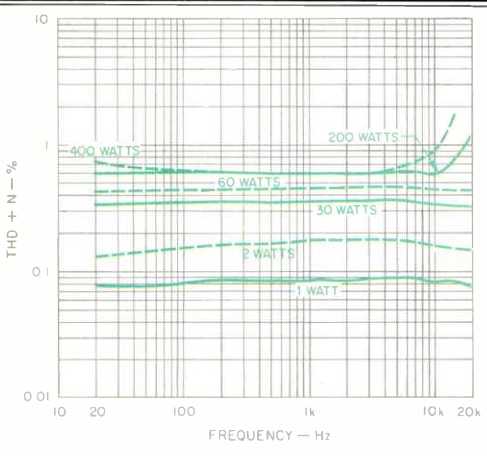
Fig. 1--THD + N as a function of frequency and power output for 8-ohm loads
(solid curves) and 4-ohm loads (dashed curves).
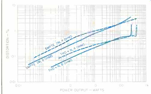
Fig. 2--SMPTE IM and THD + N vs. power for 8and 4-ohm loads.
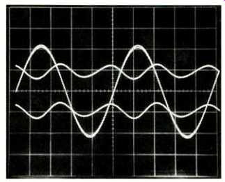
Fig. 3--Distortion residues and 1-kHz signal, for 10 watts into 8 ohms.
For left channel (upper residue trace), THD measured 0.226%; for right channel
(lower residue trace), distortion was 0.22%.
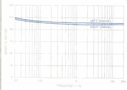
Fig. 4--Damping factor vs. frequency for 8-ohm load; see text.
Figure 2 shows THD + N at 1 kHz, and SMPTE-IM distortion, as a function of load and power output. Second harmonic distortion was the dominant order over most of the amp's power range.
Figure 3 illustrates the shape of typical harmonic distortion residues. The top trace is for the left channel, which measured 0.226%; the bottom trace, for the right channel, was 0.22%. It can be seen that the distortion character and magnitude are unusually well matched.
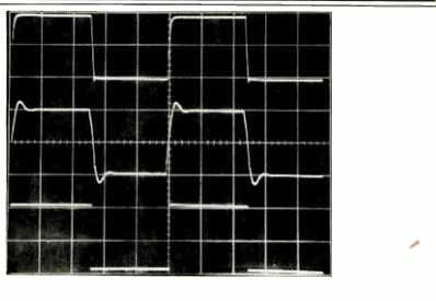
Fig. 5--Square-wave response. Top trace is 10 kHz with 8-ohm load, middle
trace is 10 kHz with 2-µF capacitance across the 8-ohm load, and bottom trace
is 40 Hz into 8 ohms. (Scales: Vertical, 5 V/div.; horizontal, 20 µS/div
for 10 kHz, 5 mS/div. for 40 Hz.)
Output noise for several measurement bandwidths and IHF signal-to-noise ratio are provided in Table I. Looking at this unit's output noise on my instruments revealed a few things of interest. With the measurement bandwidth set for wideband, normal line-voltage surges caused subsonic surges on the order of 0.5 mV in the amplifier's output. There was some microphony in the tubes due to acoustic noise or hitting the amplifier case. Generally, the amount of random noise and hum related to line harmonics was quite low in the SA-220.
Interchannel crosstalk was 6 to 8 dB higher in the right-to-left direction, where it measured -82 dB at 20 Hz, increasing to -77 dB at 100 Hz, to -60 dB at 1 kHz, and to -41 dB at 20 kHz. This amount of crosstalk at high frequencies borders on affecting stereo separation. Further, crosstalk was dependent on load current flowing in the driving channel, which suggests that the amount of crosstalk will vary with load impedance.
Damping factor versus frequency is shown in Fig. 4. Hey, look at this! Finally, an amp that has constant output impedance from 1 to 20 kHz! (I don't understand, though, why the damping factor rises a bit below 1 kHz.) The SA-220's uniformity of output impedance with frequency would likely help make this amp relatively speaker-independent, so its sound should not be affected by different speaker impedance curves.
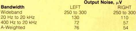
Table I--Output noise. The IHF S/N ratio was 91.6 dB for the left channel
and 94.0 dB for the right.
Frequency response at the 1-watt level was quite extended at the high-frequency end, being down about 1.2 dB at 100 kHz. Response was up to reference level at 10 Hz at the low end. Four-ohm loading resulted in a few tenths of a dB more attenuation at frequencies approaching 100 kHz.
Rise- and fall-times for ±5 V into 8 ohms were about 1.8 and 1.6 µS, respectively. 'Scope traces of square-wave behavior are shown in Fig. 5; some slewing is visible on the negative-going transition of square waves. The top trace is for 10 kHz into 8 ohms, and the middle trace is for 10 kHz into 8 ohms paralleled by 2µF. The bottom trace is for 40 Hz into 8 ohms, and excellent (read, extended) subsonic response is indicated by the small amount of tilt visible in the waveform.
Dynamic power, measured using the IHF tone-burst signal, was 289 watts into 8 ohms and 544 watts into 4 ohms.
This translates to figures for dynamic headroom of 1.2 and 1.1 dB, respectively, into these loads. Power output at clipping was 250 watts into 8 ohms and 420 watts into 4 ohms; the corresponding figures for clipping headroom are 0.56 and 0 dB. For a 1-ohm load, with only one channel driven, the amp put out ±50 V before clipping, which is also ±50 amperes-most impressive.
The SA-220's a.c. power-line draw was about 2.2 amperes, and it stayed constant within 0.1 to 0.2 ampere from cold startup through being baked in the 4-ohm power tests.
From a measurement point of view, I'd say the SA-220's strong points include low-order distortion that is constant with frequency, constant output impedance with frequency, low output noise, wide bandwidth, and high power output and current capability. On the negative side are its relatively high crosstalk at high frequencies and its relatively high amounts of measured distortion. Now, let's move on to what it all sounds like.
Use and Listening Tests
Equipment used to evaluate the SA-220 consisted of an Oracle turntable fitted with a Well Tempered arm and Koetsu Black Goldline cartridge, a Technics 1500 open-reel recorder, and a Nakamichi 250 cassette deck. My Cook King reference tube preamp and switched attenuator were used for input switching and volume control, and a Mark Levinson No. 25 phono-only preamp was used for some of the LP listening. Other power amplifiers on hand for comparison included a pair of EAR 519 mono tube units, Jeff Rowland Model 7s, and a Boulder 500AE. The speakers used were Siefert Research Magnum IIIs.
I liked the sound of the SA-220 as soon as it started to pass music through to my speakers. Music reproduced through this amp had a big, easy sound. The midrange was open and clear, the highs were airy and extended, and the bass was full and deep. The bass was not quite as tight and damped as with some other amps, but it sounded quite musical to me and blended well with the lower midrange. Depth and dimension were very good.
The SA-220 is an amplifier that satisfies my musical sensibilities and has a great measure of wallop when needed! I highly recommend prospective buyers give it a listen.
-Bascom H. King
(Source: Audio magazine, Jul. 1990)
Also see:
Counterpoint SA-220 Amplifier (ad, Feb. 1992)
David Berning EA-2101 Amp & TF-12 Preamp (Dec. 1991)
Conrad Johnson Premier Five Amplifier (Aug. 1986)
= = = =