Manufacturer's Specifications
Decoding System: 18-bit, with eight-times oversampling.
Analog Filtering: First-order, phase-linear.
Inputs: Coaxial and optical.
Frequency Response: 20 Hz to 20 kHz, ±0.5 dB.
THD: Less than 0.01%.
Dimensions: 17 in. W x 21/2 in. H x 9 in. D (43.2 cm x 6.4 cm x 22.9 cm).
Weight: 12 lbs. (5.4 kg).
Price: $799.
Company Address: P.O. Box 1119, Grover City, Cal. 93483, USA.
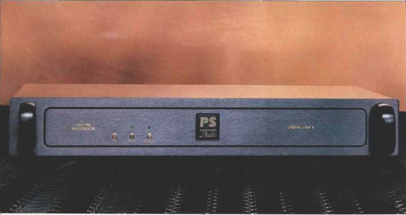
I have known the folks at PS Audio for a number of years and have frequently been impressed by their ingenuity and the timeliness of their new products. The Digital Link II is a good case in point. Here we have a relatively inexpensive digital decoder that can be used with a CD player, satellite receiver, LaserDisc player, or DAT recorder. And it sounds good to boot. There are a lot of people who would like to upgrade to outboard converters but can't afford the prices of most better sounding ones. The Digital Link II could be what these people are looking for.
The Digital Link II is an external processing unit that takes the Sony/Philips Digital Interface Format (SPDIF) serial digital output available from many CD players, CD transports, and other compatible digital sources, in either coaxial or optical form, and converts this signal to the left and right recovered audio outputs. The main reason to use a dedicated device such as this is to get better sound than the circuitry of most CD players and other digital sources can provide. The Digital Link II does the D/A decoding and feeds the audio into the system preamp.
Some of the features of the Digital Link II are automatic adjustment for incoming sampling frequencies from 22 to 50 kHz, automatic signal output muting when there is no suit able digital input signal, and the potential for upgrading to newer, better performing integrated circuit chips as they become available.
The front panel has three touch switches on the left side and a single green LED on the right side. The first switch toggles the unit between standby and operation and illuminates the LED when the unit is on. The external power supply should be plugged in all the time to keep the internal circuitry always powered up and running for best sound. The other two switches select coax or optical inputs.
On the rear of the unit are a power input connector, a phono jack for coaxial digital input, a Toslink optical connector for optical digital input, and two audio output phono jacks. All three of the phono jacks are of high quality and are gold plated.
Circuit Description
The incoming digital signal to the coaxial input is terminated with a 75-ohm resistor in the unit to match the presumed characteristic impedance of the interconnect cable. After termination, the signal is fed into a C-MOS logic inverter to amplify and square up the waveform. This inverter is biased into the middle of its linear range by a feedback resistor.
Another inverter chip follows and further squares up the signal pulses. The optical input is a neat little circuit module that converts the incoming optical digital signal to TTL logic level. Selection between the conditioned coaxial input and the output of the optical input module is implemented by a combination of three NAND gates controlled by the front panel's switch circuitry.
Next in the signal path is a digital receiver chip that performs many jobs: It locks to the incoming sampling frequency, outputs subcode information (such as presence or absence of pre-emphasis and the status of the copy enable/prohibit flag), tells whether a suitable digital signal is present or not, and generates timing and data signals.
These timing and data signals then go to an eight-times oversampling, digital low-pass filter with a cutoff frequency of about 21 kHz. This is a steep "brick-wall" filter but still has a desirable linear-phase characteristic. All of this filter action is generated by a fixed, internal digital signal processing (DSP) algorithm.
Following the digital low-pass filter are two Analog De vices 1860N 18-bit D/A converters, one for each audio channel. Converting the D/A circuit's current to an audio signal voltage usually involves the summing junction of an op-amp, but this is done differently in the Digital Link II.
Output current from each converter is fed into a low-value resistor. The resulting voltage is then fed into a passive RC low-pass filter followed by a passive de-emphasis network that's switched in when required to play a pre-emphasized disc. Next, a signal amplifier with flat frequency response builds the signal up to the several volts required at full modulation. The rationale for doing the D/A output's current-to-voltage conversion this way is to reduce the likelihood of slew-induced distortion (a possibility with the more common summing-junction approach) by keeping any out-of-band residue of the sampling frequency out of the amplifier circuit. According to PS Audio, this approach produces better sound. A measurement consequence is higher random noise in the final output or signal-to-noise ratios that are not as good as the CD medium is capable of. This increase in noise level is of little practical importance, as the noise is still far enough down to be inaudible in most circumstances.
The output amplifier is a Burr-Brown OPA602, chosen for its sound quality. A proprietary circuit is said to force the output stage of this IC op-amp to operate in Class A. This circuit is truly d.c.-coupled, from the D/A converter output to the main output, with no artificial ingredients like servo amps or capacitors in series with the shunt feedback resistor to limit d.c. gain to 1. A trimming arrangement in the output amp is used to adjust d.c. offset in the output to near zero.
The external transformer feeds in a.c. that is then half-wave rectified into two positive and two negative supplies.
This rectifier scheme uses a novel approach-two rectifiers in series, with a filter capacitor between them in addition to the final capacitor at the rectifier output. Four three-terminal voltage regulators provide outputs of + 12,-12, + 5, and-5 V. Four LEDs in series with each 12-V supply drop the voltages to make an additional ±.- 5 V supply.
All in all, the Digital Link II's circuitry has some unusual and interesting features not found in other D/A converters I've studied.
Measurements
For all my measurements, I used a Magnavox CDB-560 CD player as a transport and the CBS CD-1 test disc. The first thing I noticed when measuring the Digital Link II's performance was that its full-scale output was higher than the standard 2 V-closer to 3.4 V, in fact.
Frequency response without pre-emphasis is shown in Fig. 1. I think the slight irregularities below 20 Hz are an artifact of the test since they were not consistent in shape when I did the test at different times. High-frequency roll-off is smooth and is about 0.7 dB down at 20 kHz. Figure 2 is the response with de-emphasis switched in, and it appears to be a bit up in the high end. All other things being equal, this response will be noticeably brighter than if it were flat.
Next I conducted a series of tests for linearity of output level as a function of recorded level. Figure 3 shows the results of the dithered fade-to-noise test, while Figs. 4A and 4B show performance as deviation from perfect linearity.
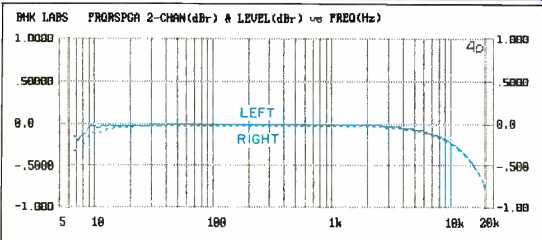
Fig. 1--Frequency response without pre-emphasis.
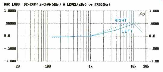
Fig. 2--De-emphasis error.
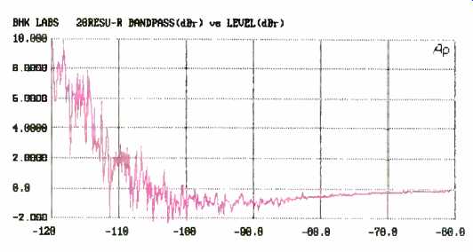
Fig. 3--Fade-to-noise test.
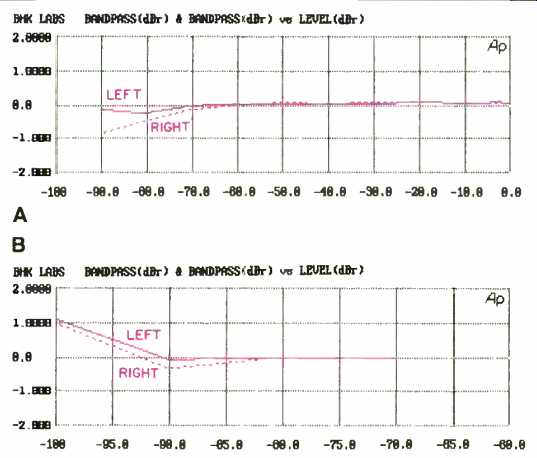
Fig. 4--Deviation from perfect linearity for undithered signals (A) and dithered
signals (B).
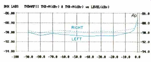
Fig. 5--THD + N vs recorded level.
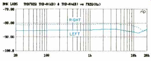
Fig. 6--THD + N vs. frequency.
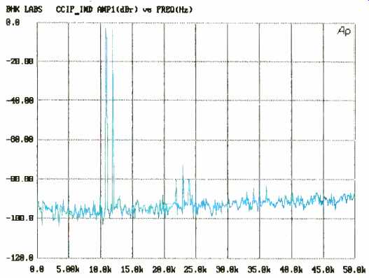
Fig. 7--Output spectrum for 11- and 12-kHz signals at -3 dB.
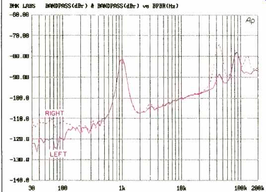
Fig. 8--Third-octave noise vs. frequency for 997-Hz tone at-80 dB.
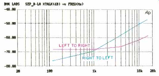
Fig. 9--Separation vs. frequency.
The apparent positive shift below -100 dB in Fig. 3 is actually an increase in noise, the result of hitting, the noise floor of the CD player or decoder, and is fairly characteristic of this test. The linearity of the Digital Link Ii is very good compared to that of other CD players and external converters I have seen measured.
Related to linearity, certainly, are various kinds of steady state distortions. In Fig. 5, THD + N as a function of recorded level with a 997-Hz tone is shown. The readings here are for THD + N as a percentage of full-scale output rather than as a percentage of actual recorded level. Figure 6 shows how THD + N varies with frequency at full recorded level.
For linearity and distortion, I measured the output spectrum up to 50 kHz with two equal-amplitude tones of 11 and 12 kHz (Fig. 7). Each of these tones is 3 dB below full scale, so their rms sum is 0 dB. The 1-kHz difference tone is about at the level of the noise and therefore doesn't really show on the plot. Second harmonics of the tones can be seen at 22 and 24 kHz, and there is a 23-kHz tone that came creeping in from somewhere. Notably absent is anything at the 44.1-kHz CD sampling frequency. This performance looks pretty good to me.
Noise within the bandwidth (approximately one-third octave) of the Audio Precision system's tracking bandpass filter is shown in Fig. 8 as a function of frequency, measured in the presence of a 997-Hz test tone at-80 dB. The noise shown rises at 10 dB per decade because it is closer to white than to pink noise. With a filter of constant percentage bandwidth such as the tracking third-octave filter used here, the density of white, or uniform, noise will rise at this rate.
Some leakage at the sampling rate, and the second and third harmonics thereof, are visible. The right channel has more noise below about 200 Hz. Some third-harmonic distortion is just visible at about 3 kHz.
Crosstalk versus frequency is plotted in Fig. 9. Results are not outstanding, but they are probably good enough to avoid affecting stereo imaging and soundstage properties.
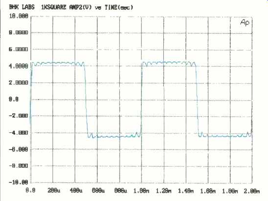
Fig. 10-Square-wave response; see text.
The impulse response of the Digital Link II (not shown) indicated that the unit is noninverting, and the nature of the ringing on that impulse showed that the unit's phase behavior is linear. The integral of impulse response is related to the step response, which is shown in Fig. 10 for a 997-Hz square wave. You can see an artifact of the Yamaha digital filter used here (and, I understand, of some Sony filters too):
With a full-scale step signal, the filter clips off the natural excursions that go above full-scale. The symmetry of the ringing again shows the filter's phase linearity.
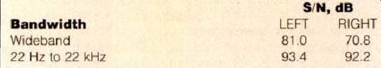
Table I--S/N ratios, referenced to 0 dB.
Signal-to-noise ratio, relative to a full-scale signal, was measured for several bandwidth conditions (Table I). The sampling frequency and its harmonics were major contributors to the wideband reading in the Table.
My measurements yielded an EIAJ dynamic range of some 94 or 95 dB for the Digital Link II. This figure is arrived at by adding 60 dB to a THD + N measurement (made with A-weighted filtering over the range from 22 Hz to 22 kHz) of a 1-kHz test tone recorded at -60 dB.
I also measured quantization noise in an attempt to assess the noise contribution of the D/A converter when handling a full-scale signal. In this EIAJ test, a full-scale signal at a low frequency (such as 20 Hz) is played, and that signal and its harmonics are removed by a 400-Hz high-pass filter.
What remains is random system noise plus the noise from the D/A conversion process--in this instance, 91 or 92 dB. This test does not use the A-weighting filter used for measuring dynamic range, so the results may really show random 'system noise rather than quantization noise per se; with quieter systems, I would expect to see true quantization artifacts, unmasked by noise, in this test.
Use and Listening Tests
When evaluating the Digital Link II, I used the Magnavox CDB-560 CD player and a Krell MD-1 CD transport plus such D/A converters as a Wadia 2000, a VTL Straight Line 20-bit model, an Audio Alchemy DDE, and a number of experimental components. The output of whatever D/A converter was in use was fed to the main input of a First Sound Reference II signal selector and attenuator, a passive model that I use in preference to having a preamp output stage in the setup. I also tried such power amplifiers as the Carver Silver Sevens, Quicksilver M135 prototypes, and an excellent switching amp now under development. The speaker systems were the Martin-Logan Monolith III, Spica Angelus, and Win Research SM-10. I had no operational problems except for an occasional mild click or pop heard when muting the Magnavox player.
I find the sound of the Digital Link II to be quite good, with excellent sense of space and dimension and well defined bass. Compared to the better (and certainly more expensive) units I use all the time, the Digital Link II is flatter spatially, and it is a bit more sterile, with more noticeable grain structure but more apparent detail and a bit more irritation. Considering the PS Audio's price and good sound, it would be a worthwhile improvement to many CD systems. In fact, a discriminating friend of mine, who has a terrific-sounding system using Apogee Divas, has been happily listening to CDs through a Digital Link II for months.
In summary, I think the PS Audio Digital Link II is a very good-sounding decoder, and it may well be what you have been waiting for. Go get one and enjoy.
-Bascom H. King
(This article adapted from Audio magazine, July 1992.)
============
Also see:
PS Audio Ultralink D/A Converter (Equip. Profile, Aug. 1993)