Line Radiators for Public Address
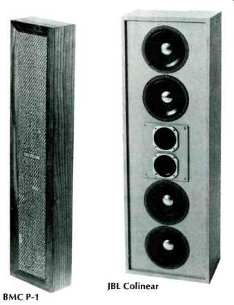
BMC P-1; JBL Colinear
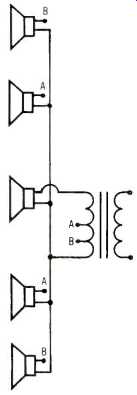
Fig. 1--Showing one method of power 'tapering.'
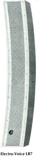
The BMC model P-1 column at the far left has an array of six 4M-inch speakers fitted with dispersion domes. Response is said to extend down to 40 Hz and the dimensions are 33 1/2 by 8 1/2 by 5 inches wide. Model P-2 is a smaller version measuring 29% inches high with a reduced bass response. JBL's 4380 is called a ‘Colinear' array and it uses four 8-inch speakers with two 5 inch high-frequency units. Horizontal radiation is 120 deg. and 20 deg. vertical. The University CSO-6G 'Uniline' is completely weatherproof and constructed to withstand severe environmental conditions. It uses six 8-inch speakers and the two middle units have `whizzer' cones to increase h.f. response. Dimensions are 6032 by 11 by 7% deep and the frequency response is given as 65 Hz to 14 kHz. The small system is a Geloso model 10T/98 which employs three 5-inch speakers. The ball-type swivel permits a wide range of adjustment and among the other features is a variable thumb-type impedance selector. This `mini-column' is ideal for low-level background music or paging systems. Dimensions are 1933 by 4 by 3 inches deep. The large curved system is an Electro-Voice LR7 which has no less than nine 5 by 7-inch speakers plus two compression tweeters. Frequency range is 50 Hz to 17 kHz and dimensions are 60 1/2 by 11 by 14 inches deep.
Line-source, or sound-column systems consist of several speakers mounted vertically and spaced as close as possible in an enclosure. Such systems project the sound forward in a horizontal beam with minimum side and rear radiation. Reflections from walls and ceilings are reduced making for better intelligibility, and the sound pattern allows a greater latitude in microphone placement to avoid feedback. Usual lengths are 4 to 7 feet which to some extent determines the low-frequency response in accordance with the' following formula:
1= [720/f_1 sin_theta] ft
Where fi lowest working frequency
θ angle a which intensity is -6 dB at f1
In order to maintain a uniform high-frequency response, i.e. to prevent undue beaming effects, it is customary to tailor the response of the units or use series inductors for the top and bottom units.
To arrive at the required wave shape with a minimum of side-lobes, input should be distributed with full power applied to the middle units and tapered off at each end. This is usually accomplished by using taps on the input transformer as shown in Fig. 1. In outdoor systems where reflections from walls do not reinforce the sound, it is worth remembering that doubling the distance from speaker to listener reduces the sound pressure by 6 dB. To make this up, amplifier power would have to be increased by a factor of four.
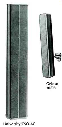
University CSO-6G; Geloso 10/98; Electro-Voice LR7
At the upper left of the page is the Jensen TXC-56 system which uses six 5 1/4-inch speakers. Frequency response is quoted as 100 Hz to 10 kHz, and the dimensions are 40.5 by 9.5 by 5.5 inches deep. Model TXC-84 is similar in styling, but is fitted with four 8-inch units, and the frequency response is extended down to 50 Hz and up to 15 kHz. Dimensions are 52.5 by 13.25 by 7% inches deep. At the right is the Electro-Voice LR4SA, which is described as an all-weather line radiator. It comprises six 5by-7-inch speakers, and the frequency response is given as 200 Hz to 10 kHz. Dispersion is 120 deg. horizontal and 30 deg. vertical.
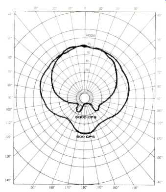
Fig. 2-Horizontal dispersion of Bozak system.
The enclosure--which is made from extruded aluminum--is 48.5 by 6.25 by 4 inches deep. At the left is a Bozak CM-200-10 mounted on a pole. This system is intended for areas with severe reverberation problems and the bass response rolls off below 200 Hz. It comprises two 6-inch speakers with eight 2-inch treble units. The polar diagram shown in Fig. 2 is the horizontal dispersion pattern at 500 Hz and 5 kHz. Model CM-109-18 is a larger system with a low-frequency response going down below 100 Hz, and it uses six 8-inch speakers plus twelve 2-inch treble units. It is somewhat larger, measuring 57 by 15% by 10 inches deep.
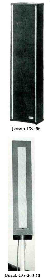
Jensen TXC-56; Bozak CM-200-10; Electro-Voice LR4SA
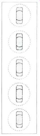
Fig. 3--Method of slot-loading.
The diagram of Fig. 3 is that of a slot-loaded enclosure as used by Bozak. These are very popular in Europe and are used extensively for airport installations. Care has to be used in design to avoid cavity effects. The majority of enclosures are sealed, but reflex loading with narrow ports is sometimes used in the larger systems.
Electronics for Public Address
NORMAN H. CROWHURST
PUBLIC ADDRESS SYSTEMS are the story of overcoming acoustic problems. From the earliest days, this consisted of using one or more microphones with one or more loudspeakers to make the program sound-someone speaking or a musical performance-more audible to the audience.
If acoustics are not very bad, a relatively simple arrangement of microphone, amplifier, and loudspeakers does the trick.
But then, when the acoustics are not bad, possibly the auditorium does not really need reinforcement in the first place, except maybe for the speaker or vocalist who has always used one and cannot be heard without. Apart from this, sound reinforcement is more generally needed where the audience cannot hear without it, which means the acoustics are not good, one way or another.
So various tricks were used fairly early in the game to help the system do a better job than the simple microphone, amplifier, and loudspeaker combination could do, with no trimmings. The recurrent problem has always been acoustic feedback, from the loudspeakers to the microphone, before adequate `gain' could be obtained to make the program more audible to the audience.
Transducers Before we turn to the purely electronic devices, it will be well to emphasize something that time and again has been found to be very important concerning the electroacoustic devices-microphones and loudspeakers: they must be as flat as possible in their frequency response--free from peaks and dips.
Acoustic feedback always occurs first at some specific frequency: that is where the trouble begins. In a good system, feedback should be almost ready to start at many frequencies at the same time, over a fairly wide frequency band. The presence of marked peaks in either the microphone or the type of speakers used, will result in a tendency to start a feedback howl at one of these peak frequencies while the general reproduction of adjacent, non-peak frequencies is still quite inadequate.
Auditoriums also exhibit frequencies at which feedback more readily starts, often due to natural resonances associated with the dimensions of the building. But in few instances are these peaks nearly as difficult to manage as are those peaks that occur in microphone or loudspeaker response. When an acoustic howl starts, it sets up a standing wave pattern in the room, and this pattern is usually related in some way to the dimensions of the room.
If the system, from acoustic input to the microphone to acoustic output from the loudspeakers, is close to flat, the correction needed to minimize the effect due to building acoustics is usually not serious, but it can be very helpful.
Acousta-Voice
This is the approach used by Altec Lansing's "Acousta-Voice" method. Acousta-Voice is not so much a system as an approach to doing the job. The Acousta-Voice engineer, trained by Altec's people, visits the auditorium and conducts a real-time analysis of the building's acoustics, to find where its peaks and valleys are.
These are carefully and precisely analyzed and then a permanent filter is adjusted to offset the acoustic deviations from flat response. When the Acousta-Voice filter is inserted into the system, the overall response of the system, in that auditorium, is flat.
This enables the system to be operated at notably more gain than is possible without the correction, and the performance is more free from noticeable coloration at the level where it is operated.
Perhaps Acousta-Voicing can be regarded as a refinement of the older methods that employed tone controls and notch filters. The main difference is that the old method used controls that were available on a specific system, or some components thrown together by a man with a good "ear" for such things, and thus matched the performance, as well as possible, to the needs of the moment. To a considerable extent, this method depended on, and was limited by, the skill of the operator. Acousta-Voicing is more precise, scientific, not subject to trial and error, or hit and miss.
Frequency Shifting
Another approach that seems to have fascinated many because of its sophistication, is the frequency-shifting principle.
Every input frequency is shifted a few hertz up or down, so the frequency content in the output from the loudspeakers differs from that going into the microphone, although the intelligible content of the program is virtually unchanged.
This method has proved successful, if expensive, on speech, but for obvious reasons, it is not good for music. Shifting frequency, say 5 Hz, in the upper register may Make little enough difference that only"' highly skilled musician would notice it. But down in the bass register, the same 5 Hz could be a change in pitch of a semitone or two, which would be disastrous to the musical effect, even as discerned by a musically untrained ear.
Possibly frequency shifting would have proved far more popular for situations where speech-only is a reliable expectation, if it were not for the fact that, being highly sophisticated, it is also costly.
Acoustic Nulling Another approach to the acoustic feedback problem is worth noting, and putting in perspective relative to other efforts, so confusion between different methods is avoided. This has been the subject of some experiments conducted by Electro Voice in collaboration with Brigham Young University.
While it involves additional electronics to do the job, it relies on acoustic nulling of the feedback signal. If two loudspeakers are connected anti-phase and a microphone is placed precisely equidistant from them, as in Fig. 1, and their levels are adjusted so the intensity received from each is equal at the microphone, the acoustic field at the microphone is a null, and much more gain can be used.
One's first reaction to this will probably spring from observations in earlier systems when speakers were accidentally connected out of phase: the auditorium coverage is poor, because of dead spots where signal cancels and listeners at these points receive only reverberated signal, highly confused. But the Electro-Voice approach goes two steps beyond this to overcome the defect.
Instead of using just one microphone on one acoustic null point, a multiple system is used, such that each microphone is at a null point for the speakers fed by that microphone's amplifier system as in Fig. 3. Now every individual system can be operated at a higher gain than any system can be operated in that auditorium without using this trick, and no listener is going to be located at a null point for more than one of the multiple systems used.
An important part of the successful application of this method is that the microphone on each system must be equidistant from the two loudspeakers on the same amplifier that are connected anti phase, by direct path. Feedback of the conventional type occurs due to standing wave patterns building up. The usual practice of avoiding direct-path feed from loudspeakers to microphone means the first howl frequency occurs using a complicated path, rather than the simple direct one. (Fig. 2).
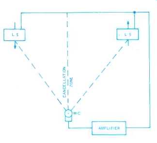
Fig. 1. The basic arrangement developed by Electro-Voice.
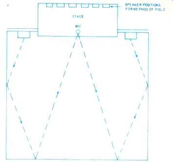
Fig. 2. For comparison, a more conventional system tries to avoid direct-path feedback from loudspeakers to microphone, so that acoustic feedback at a frequency starting a howl may take the paths shown here by the dashed lines.
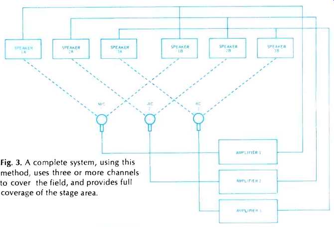
Fig. 3. A complete system, using this method, uses three or more channels to cover the field, and provides full coverage of the stage area.
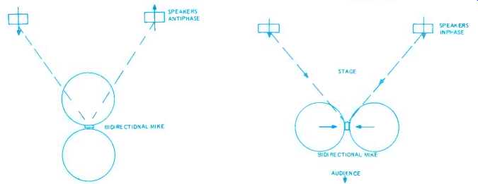
Fig. 4. A bidirectional mike could also use this system, although Electro-Voice does not recommend it.
Fig. 5. An alternative way of using a bidirectional mike with similar effect, with the loudspeakers in phase and the microphone pickup from them antiphase.
This was actually used long before this new development.
So placement of speakers needs to be quite different to utilize this approach.
There must be a deliberate direct feedback path from each, or the cancellation will not occur uniformly over the frequency range. But the completeness of cancellation means that gain can still be elevated, in comparison with the more usual arrangement. And the multiple system use means that each system carries only part of the total sound conveyed to the average listener, and thus each can be operated at a level lower than the normal, single-channel system.
The system has another bonus. In most conventional systems, the performer or speaker hears his own performance or, voice come back to him only by reverberation. With this method, he hears the system direct, just as the audience does.
Another difference should be noted.
In conventional systems, microphone placement is not usually highly critical.
In the Electro-Voice system, the microphone must be located very accurately in relation to the two loudspeakers connected to the output of its amplifier. Any movement of the microphone, not along the line of cancellation, will invalidate the cancellation very quickly and cause trouble.
The Electro-Voice people use omnidirectional or cardioid mikes with this system, never bidirectional types. It would be theoretically possible to use bidirectional mikes, except that now the mike must not only be kept in the same place, it must not be rotated at all. The system must be kept completely symmetrical (Fig. 4).
Another possibility, similar to the Electro-Voice in principle, has been used with bidirectional mikes, long before the loudspeaker antiphase method was used.
This uses the bidirectional mike so its position and orientation neutralizes feedback by antiphase at the mike, rather than the loudspeakers, thus avoiding the need for a multichannel system (Fig 5).
This arrangement is particularly good for interview or dialog, with one person on each side of the mike from the audience's viewpoint, so the mike does not obtrude between the participants and the audience.
The Electro-Voice multichannel system is intended for wide-field (full-stage) coverage, rather than just single-person pickup. And for this purpose it simplifies the system. To use a conventional system for this purpose requires a number of mikes and, for best results, mixing and gain riding is necessary. With the system just described, the system is set up, correctly nulled acoustically for each amplifier, and the amplifiers need no gain riding during a program.
The important thing to realize, in comparing systems, is that a completely different approach is used. A conventional system cannot be changed to the Electro Voice system just by altering a few connections. A completely different speaker placement must be used. Low-level speakers throughout the auditorium, as used by some other systems, will not work where this method is used.
For the conventional approach, the P.A. system serves a function that can be considered as modified "relay." True, the loudspeakers may be in the same room with the microphone, but they work because they are removed as far as possible--trying to be in a different `part' of the room, to which sound is thus 'relayed'. For the Electro-Voice approach, the P.A. system is essentially a reinforcement system, as was never the case with conventional systems. It reinforces the sound level, right where it starts, on stage, or wherever the program originates. This is the important difference.
Amplifiers Now for a few differences in public address amplifiers. Tubes are almost, if not quite, passe. Solid state provides complete freedom from microphonics, as well as greater compactness and efficiency. The one weak point about transistors is their susceptibility to blowing if they are accidentally overloaded, which is easier to do with them than with tubes.
Mismatching the output, for example, can result in transistors trying to deliver many times their normal rated output audio current, which will not take long to blow them if it is allowed to happen.
The first step toward protection was the insertion of current-limiting circuits that cut back the input when output current reached a predetermined maximum, of which Fig. 6 is a sample.
Transistors Q1, Q2 are the output, driven by complementary pair Q3, Q4.
Resistors R1, R2 produce a voltage drop due to output current from their respective output transistors. When this exceeds the contact potential of either protection transistor Q5 or Q6, the latter starts to conduct, bypassing the base current to Q3 or Q4, and holding output current to that required to produce the contact potential for Q5 or Q6. Q7 provides the voltage swing. Dl and D2 prevent Q5 or Q6 from conducting in reverse on the half-wave of signal for which they are not intended to be operative. D3 and D4 provide the contact potential to maintain a quiescent output current.
This kind of circuit prevented output transistors from being blown by excess audio output current. But then another possibility showed up: excessive dissipation. If output current reaches its maximum into a load whose impedance value is only slightly lower than nominal, the voltage drop across the output transistors at this maximum current will be small and safe.
But suppose the impedance connected to the amplifier output is much nearer to a short-circuit than that: now the voltage across the load when maximum current is reached will be almost zero, which means all the supply voltage is being dropped across the transistors, which are working at maximum current already. This situation will certainly exceed the transistors' permitted dissipation.
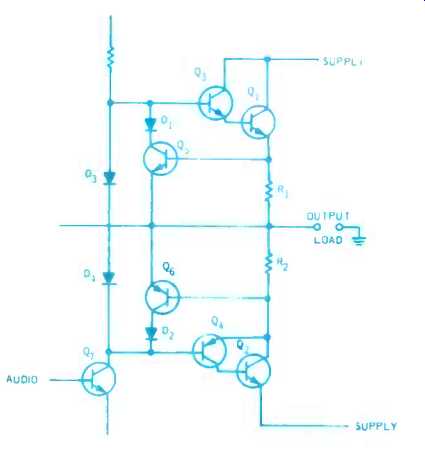
Fig. 6. A typical protection circuit to provide maximum current protection for output transistors.
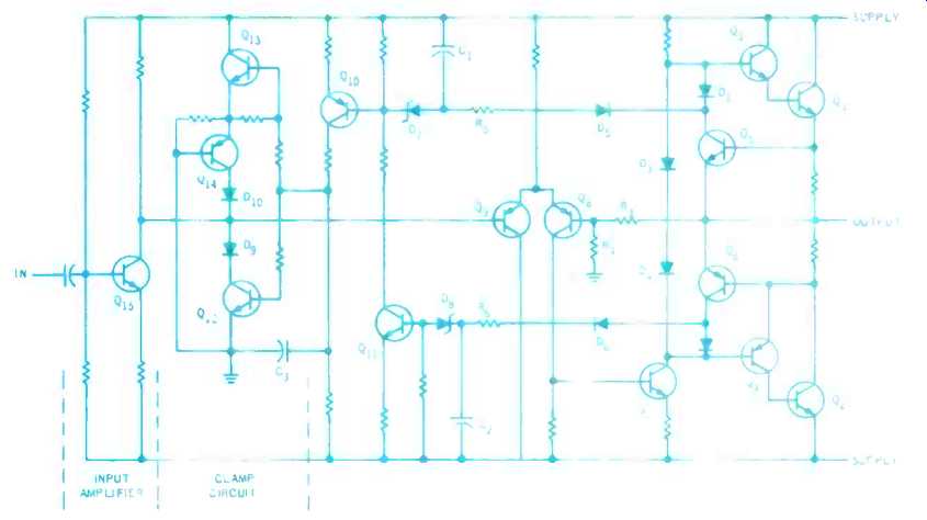
Fig. 7. One version of a more complete circuit that adds dissipation protection. Parts serving the same function are numbered the same as in Fig. 6.
There just is no way to hold both these quantities in bounds at the same time. Voltage drop across the transistors could be reduced by allowing output current to rise, but the transistor is going to be overrated whatever you do, until a correct load is connected to the output, by which time it may be too late to save the output transistors.
So the protection circuit devised against this possibility cuts off the input when a dangerous condition of this kind presents itself (Fig. 7) . Zener diodes, D7, D8 sense when the voltage drop across an output transistor is too great, at the time current limiting comes into action, causing Q5 or Q6 to conduct.
When the protection triggers, Q10 charges C3, which causes the clamp circuit to ground the signal output from input transistor Q15. Resistors R5 and R6, in conjunction with capacitors C1 and C2 allow greater overloads of very short duration, but act if the overload lasts long enough to cause damage at a lower dissipation level. Q8 is a feedback transistor, sampling the output through R3, R4; Q9 combines feedback with input at this point.
The signal stays clamped until C3 discharges, allowing Q12 and Q13 to return to their normal non -conducting mode. In normal operation, all transistors Q5, Q6, Q10, Q11, Q12, Q13, and Q14, used for protection are non -conducting. The remaining transistors serve the normal amplifying functions.
The time constants associated with C1, C2, and C3 are chosen to provide guaranteed protection, with minimum unnecessary interference with signal. This is one variation of a whole range of new circuits that are making transistors as "foolproof" as tubes.
(Audio magazine, Aug. 1970)
Also see:
Another Look At Parallel-Connected Loudspeakers (Nov. 1970)
What Price Loudspeaker Response Curves (Mar. 1972)
Speaker Tests: Room Test by Richard C. Heyser (Jan. 1975)
Speaker Tests--Phase Response (by Richard C. Heyser) (Dec. 1974)
The Acoustic Feedback Loudspeaker System (Jan. 1972)
= = = =