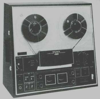
MANUFACTURER'S SPECIFICATIONS:
Speeds: 7 1/2, 3 3/4, and 1 7/8 ips.
Maximum reel size: 7 in.
Motor: One, vibration free induction.
Heads: Three-erase, record, play; quarter-track.
Semiconductors: 27 transistors, 4 diodes, 1 Zener. S/N: 55 dB (with SLH tapes), 52 dB (with standard tapes).
Frequency Response: 20-25,000 Hz at 7 1/2 ips; 30-17,000 Hz at 3 3/4 ips; 30-9,000 Hz at 1 7/8 ips.
Wow and Flutter: .09% at 7 1/2, 0.12% at 3 3/4, 0.17% at 1 7/8. Inputs: Microphone, low impedance, 0.19 mV; Auxiliary, 100k ohms, .06V.
Outputs: Line, 0.775 V, 100k ohms impedance; headphone, 8 ohms, 30 mV.
Dimensions: 16 7/8" wide, 8 5/16" high, 14 13/16" deep.
Weight: 22 1/2" lbs.
Price: $229.95.
The new model TC-366 replaces the well-known 355, which has long been a popular deck. The new features of the 366 should ensure even greater acceptance than its predecessor. Among these features are its ability to accommodate both microphone and line inputs simultaneously with mixing between them, an automatic total-mechanism shut-off, tape-equalization selector switch, faster forward and rewind spooling, and the absence of pressure pads-always a decided advantage. Another of its plus features is the unique cabinet which provides for either vertical or horizontal mounting of the chassis to the user's choice.
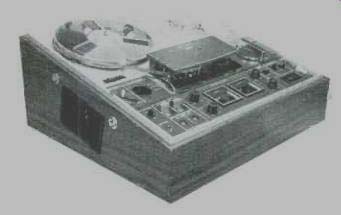
Fig. 1--The 366 remounted in its cabinet for horizontal operation
Physically the TC-366 is in a slant front case which can be used in the vertical position, or if the user wants to place in the horizontal position he removes it from the case and turns the deck around and remounts it, with a slanting front panel in a position which makes it easily accessible in addition to being attractive in appearance. The upper section of the molded plastic panel is fitted with the two reel hubs flush with the satin-finished aluminum surface. The panel is stiffened on all four sides by extruded aluminum trim strips. An aluminum strip across the center of the front serves as a divider, and accommodates the four-digit counter at the left. Centered on this strip is the removable head cover, finished in dark gray trimmed with aluminum. The base of the head assembly is finished in polished chrome. To the left of the head cover are the pause lever ( which can be operated momentarily, or locked in the stationary position ), and to its right the speed-control knob. On the other side of the head cover is the operating control with its REWIND, STOP, FORWARD, and FAST FORWARD positions.
Below this section to the far left is the noise reduction switch, followed by two RECORD levers in a bright red, the left channel record-level controls-one for microphone and one for the auxiliary input. Next comes the two VU meters, with a red indicator light showing when recording, or when setting levels before starting the tape motion. To their right are the two record-level controls for the right channel. Next comes the tape selector switch and then the two monitor switches, one for each channel, which permit monitoring on either channel from the source or the tape. To the far right is a power indicator light just above the white rocker-type power switch. At the far left corner is the stereo headphone jack.
The auxiliary input and line output phono jacks are accessible through an opening on the left side of the wood case, and the power cord comes out a similar opening on the right side. The microphone(s) are plugged into miniature phone jacks located just below the two record levers. When the tape is stationary, the deck can be put in the record mode in either or both channels to permit setting levels before starting the recording.
This operation requires that the monitor switches be in the source position. After starting the recording, both monitoring and VU meter indication can be furnished by source or tape, at the operator's discretion. Headphone monitoring is fed from an emitter follower through a step clown transformer which matches the transistor to 8-ohm phones--the ones most likely to be readily available to the user of the machine.
The transport mechanism is of the proven type used in many of the Sony models. The resiliently mounted induction motor drives the capstan by an idler between the three-step motor shaft and a two-step flywheel. The highest speed uses the largest diameter of motor pulley and the smaller diameter on the flywheel.
For the two slower speeds, the idler contacts the larger diameter of the flywheel, thus ensuring a larger motor-shaft diameter. The take-up spindle is driven from the flywheel by a rubber belt, and for fast forward and rewind, the spindles are driven by idlers, one of which gets its power from a pulley on the motor shaft.
The motor is resiliently mounted to eliminate vibration, and the effectiveness of this mounting is shown by the low flutter-and-wow figure. There is a brake on the feed spindle which is released by tape tension across au arm in the tape path.
The tape passes under the brake release arm and under a tape guide fitted with a tapered entryway which directs the tape into the guide accurately, then past the automatic shutoff lever which actuates a switch for the motor as well as a trigger which releases the operating knob unless the tape is threaded through the machine. The tape then passes over the erase head and the scrape--flutter filter--which is a precision idler roller that eliminates modulation distortion. It then passes the non-magnetizing record head, the tape lifter bar, then the well-shielded play head and finally the capstan. Before being wound onto the takeup reel, it passes another guide, ensuring clean wind.
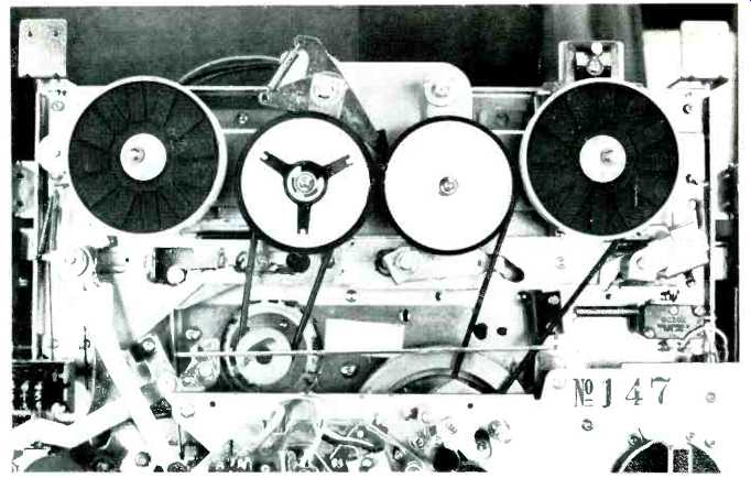
Fig. 2-Drive Mechanism. Lever at left controls drag on feed reel, applies
brake on runout or tape breakage. Note two-stepped flywheel.
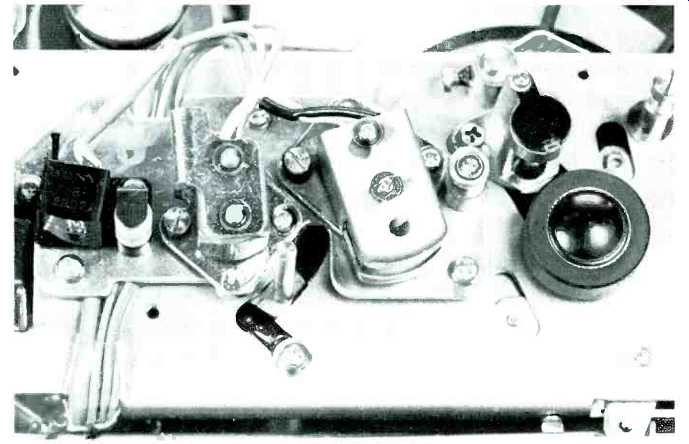
Fig. 3--Close-up of head assembly.
Circuit Description
The electronics of the 366 are relatively simple. The record amplifier uses five transistors per channel--two as a feedback pair for the microphone preamplifier, followed by the Mic level control. The Aux input level control and the mic level control feed an emitter follower through isolating resistors, and the output of the follower is fed to the source/tape monitor switch, and to the equalized two-stage record amplifier. Bias and erase current are supplied by a self-balancing push-pull oscillator. Supply voltage to the oscillator is fed by the channel record switch to the selected record and erase heads, and through two additional switches actuated by the operating lever for safety. Oscillator output builds up slowly due to a delay network in the supply circuit, and bias is adjusted by a variable capacitor and an equalizer switch which reduces the bias in two steps for the lower speeds.
The playback amplifier utilizes six transistors--the first three as a feedback equalized preamp ending up with an emitter follower which feeds a level-adjusting pot that balances source and tape levels.
Following the source/tape selector switch is a two-stage amplifier which accommodates the noise suppressor circuit--simply a roll-off, with the effect shown in Fig. 3--and a compensating adjustment for the type of tape used, normal or low noise-high-level. Additional compensation is provided in the record amplifier to ensure flat response on either type of tape.
If you record on low-noise tape with the normal setting, you will have a response which rises in the upper mid-range frequencies. The equalized two-stage amplifier is followed by another emitter follower which drives the headphone transformer and the record-level meter.
The power supply provides a 2-volt winding for the indicator lights, as well as a center-tapped 52-volt winding feeding a full-wave diode pair, followed by a three-transistor regulating circuit to supply 25 V to the amplifiers and the bias oscillator.
Performance
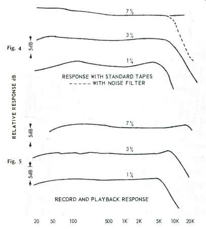
Fig. 4--RESPONSE WITH STANDARD TAPES WITH NOISE FILTER; Fig. 5--RECORD AND
PLAYBACK RESPONSE.
Figure 4 shows the response to standard tapes for the three speeds, and Fig. 5 shows the record/replay response, using the sample of Sony Low-Noise-High-Output tape that is furnished with the machine. We measured wow-and-flutter at .07 percent at 7.5 ips, with most of the contribution in the 6- to 250-Hz region. At 3 3/4 ips, wow-and-flutter measured 0.1 percent, and at 1%, it was 0.14 percent, all being below specifications. Bias frequency was noted as being 160 kHz, common to most recent Sony models, and an excellent assurance of complete absence of any interference with pilot or switching frequencies when recording from FM stereo. Distortion measured 1.0 per cent at indicated 0 VU at 1000 Hz, 0.4 percent at 10,000, 5000, and 100 Hz, with an increase to 0.8 per cent at 50 Hz. The 3 per cent distortion point was reached at an indicated recording level of +4.5 dB, resulting in a signal-to-noise ratio of 54 dB with standard tape and 57 with the low-noise product.
An input signal of 0.1 mV at the microphone jack was sufficient to give a 0-dB recording level, as was an auxiliary input of 0.32 V at the maximum settings of the record-level controls. Line output for a 0-dB recording level was 0.78 V, and the level difference between source and tape was less than half a dB. Rewind time was a very fast 110 seconds for 1800 feet of tape, and fast forward was clocked at 115 seconds, both extremely fast for a consumer-type machine. Channel separation was almost identical with the signal-to-noise figure -54 dB with standard tapes, and 56 with low-noise tape.
There is no question that the TC-366 is a worthy successor to the long accepted 355, and after several hours of various types of recording, we found no tape spillage and no broken tapes, no matter how hard we tried. The enforced delay between fast wind and ordinary recording or playing with the capstan drive prevents any of these undesirable happenings. The "retractomatic" pinch roller, which rises and moves toward the capstan as the machine is started makes it exceptionally easy to thread the tape, since the roller is well out of the way during this operation. We could sum up by saying that the 366 is simple and uncluttered, but that it has all the functions necessary to the average recordist.
-C. G. McP.
(Adapted from: Audio magazine, Aug. 1970)
Also see:
Sony PCM-2500 Digital Audio Tape Recorder (EQUIP. PROFILE, Feb. 1989)
Sony PCM-1 Audio Unit (Mar. 1980)
Sony TCD-D3 DAT Walkman Recorder (Jan. 1991)
Hitachi PCM-V300 Digital Audio Recorder (Jun. 1982)
= = = =