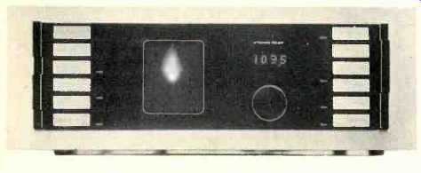
We have just seen, tested and listened to the world's best performing tuner, and it is called the Sequerra Model 1. We have just seen a most effective panoramic frequency analyzer and field strength meter for the FM frequency band and it is called the Sequerra Model I. We have just seen a four-quadrant vector-oscilloscope capable of visually depicting stereo and quadraphonic signal separation and phase relationships, and it is called the Sequerra Model 1.
This report is somewhat different from our usual product test reports for several reasons: When we learned of the performance capability of the Sequerra Model 1, we concluded that the equipment in our laboratory would be totally inadequate for measuring the important parameters of this FM tuner, and so we arranged to conduct our tests right at the Sequerra engineering and production facilities, in Woodside, New York. We were thus provided with an in-depth understanding of the Sequerra operation and can speak with some knowledge of the lengths to which that company has gone to provide the performance and reliability built into the Model 1.
After completion of our usual tests, we were somewhat shocked to find that Sequerra's "published specifications" are so conservative that they simply do not do the product justice.
That is why they do not appear as the opening paragraph of this report. For the record, here they are:
MANUFACTURER'S SPECIFICATIONS
IHF Sensitivity: Less than 2.00 uV.
S/N Ratio: Greater than 70 dB.
Ultimate THD: 0.07%.
50 dB Quieting Sensitivity: Less than 2.8,uV.
THD at 50 dB/SN: Less than 0.3%.
Frequency Response: ±0.3 dB, 30 Hz to 15 kHz.
Stereo Separation: Greater than 50 dB.
Stereo THD: Less than 0.2%.
Sub-Carrier Rejection: Greater than 70 dB.
SCA Rejection: Greater than 75 dB.
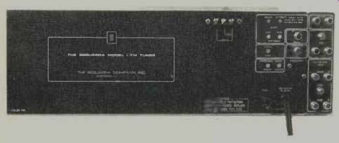
Fig. 1--View of the rear panel.
Now that you've read these few specifications, forget about them. They don't begin to tell the story. And, if you're wondering why some of the other commonly quoted specifications are not listed, be patient. It will all come clear shortly.
The product that confronted me when I walked into Richard Sequerra's expanding facilities is pictured here, but again, the simple elegance and beauty of its gold-and-black, heavy front panel cannot come across in a black and white photo. There is only one knob on the entire unit-the tuning knob. It is black, it looks good, and it rotates smoothly. Blending discreetly with the edges of the black central area are twelve pushbuttons, six along each edge. The left group include four buttons that determine what the 4 1/2-in. flat-face instrument oscilloscope tube will display. If purchased with the panoramic analyzer option (first production runs all include this feature, because everyone seems to want the feature), the first button will cause a panoramic view of all broadcasting stations located 1 MHz above and below the tuned frequency to appear on the 'scope face as vertical "pips." More about the usefulness of this feature later. Depressing the tuning display button switches in a tuning display which shows instantaneous carrier deviation of the tuned FM station, signal strength (readable with incredible accuracy over a range of greater than 90 dB-from a few microvolts to close to a volt) and any AM products resulting from multipath reflection problems. The third button changes the display to a center-origin X-Y vector display which depicts left and right stereo channels in proper spatial relationship (pure left results in a vector pointing to the left upper corner, pure right points to the upper right corner). This display is used in checking separation and phase characteristics of stereo program material. The fourth display button provides access to four rear-panel input jacks for displaying external audio information of monophonic, stereo or four-channel sources. The fifth button of this group selects high-frequency blend during reception of weak stereo signals, to reduce noise at the expense of high frequency separation. The lowest button at the left introduces a Dolby "B" decoding circuit to be used when listening to stations employing the Dolby noise reduction method in their broadcasts.
Above the single tuning knob there appears the word "Megahertz" when power is applied, and just above that is a digital readout window which reads out frequencies to which the Model 1 is tuned. Readouts are in increments of 100 kHz (rather than 200 kHz, commonly used on other digital-readout tuners we have seen) for greater precision and because some countries of the world assign FM frequencies at "even" points rather than at "odd" 100 kHz increments as is done in the U.S. Above the readout window, the words "Stereo Pilot" light up whenever the set is tuned to a station which is transmitting a stereo pilot. The right-hand row of buttons consists of three interlocking switches which turn muting off, turn interstation muting on or mute everything but stereo transmissions. The three remaining push-push buttons select automatic stereo or mono, normal or dimmed panel illumination, and turn power on and off to the entire unit. Interestingly, there isn't a "commercial message" on the entire front panel other than a distinctive "S" (for Sequerra) engraved on the power on/ off button. Sequerra feels (and we agree) that "everyone will know."
The rear panel, shown in Fig. 1, contains a three-terminal strip for connection of either 75or 300-ohm transmission lines from antenna. Clustered at the right are seven screwdriver adjustment controls, fixed and level-controlled pairs of output jacks, four external input jacks for connection of external audio channels in conjunction with the vector X-Y display on the 'scope (together with a four-section level control to permit setting display amplitude), a detector output jack, an accessory 10-terminal socket (intended for use with such accessories as a remote tuning control which will be available at a later date) and a "25 microsecond" Dolby jack. Since Dolby has suggested that his noise-reduction system could be put to best use if FM pre-emphasis and de-emphasis were officially changed to 25 microseconds (instead of the present 75 microseconds), Sequerra has provided this last feature which simply requires the insertion of a shorted "phono plug" to change the de-emphasis time constant internally.
The seven screwdriver adjustments accessible to the user include focus, intensity, vertical centering and horizontal centering for the 'scope display, muting level adjustment (from 3 microvolts to 30 microvolts) and two adjustments for centering the panoramic frequency display and for controlling its width. A one-ampere fuse holder and line cord complete the back panel layout.
Circuitry and Internal Construction
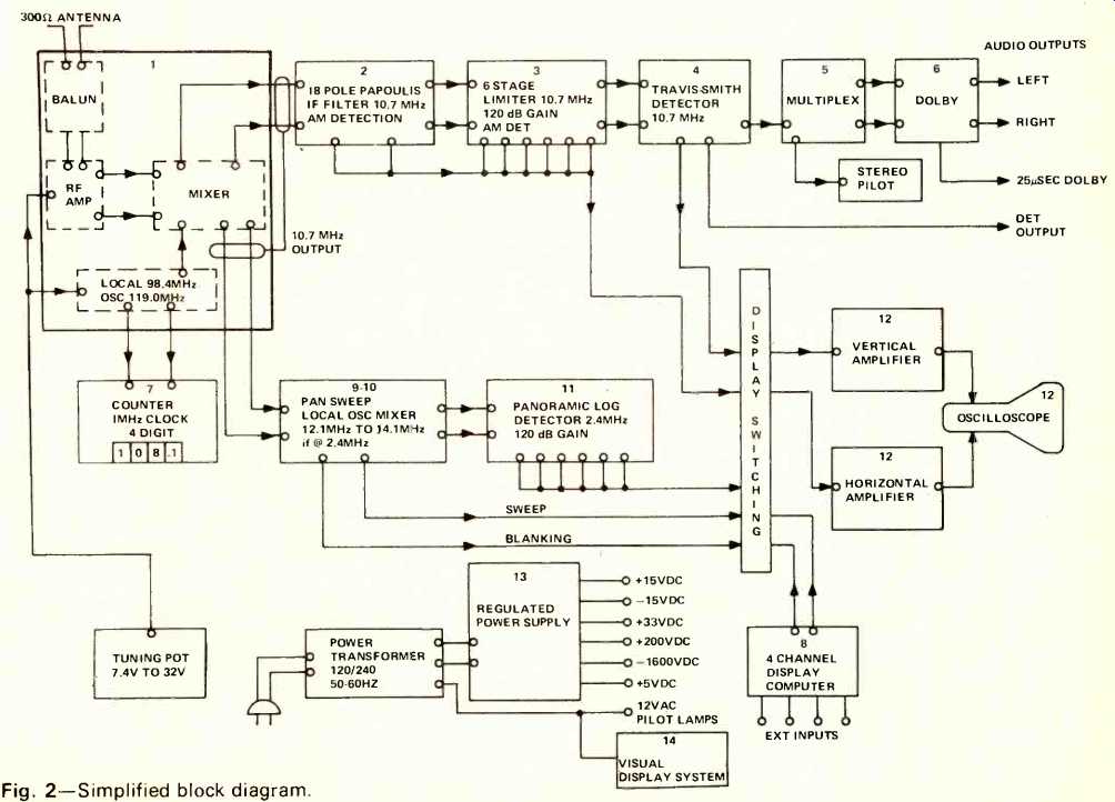
Fig. 2--Simplified block diagram.
The block diagram of Fig. 2 should give you some idea of just how much sophisticated circuitry has been built into the Model 1. The photo in Fig. 3 is a view of the inside of the chassis, taken from the top, with the black cabinet wrap removed. The frontend of the tuner is unique in that it employs "balanced" circuitry all the way from the differential push-pull cascode r.f. input amplifiers (4 FETs) all the way to the balanced push-pull FET mixer stage which is "source" driven by a balanced transformer and whose "drain" outputs feed another transformer.
In addition to the normal i.f. output, the front-end supplies outputs to the 4-digit, 1 MHz clock counter and to the panoramic analyzer section. The r.f. section is varactor tuned, with tuning voltage ranging from 32 volts to 7.4 volts. Multiple varactor diodes are "stacked" for higher capacitance.
The i.f. section, shown in Fig. 4, contains an 18-pole Papoulis filter, each section of which contains 3 separate coils and two adjustable coupling capacitors.
There are six limiter stages, as seen in the view of Fig. 5, each with a gain of approximately 20 dB. AM detection points are taken from the i.f. filter and limiter sections and fed to the display section for use in its "Tuning" mode.
A newly designed Travis-Smith FM detector utilizes 2 peak detectors in quadrature. This arrangement serves to balance out 2nd and 3rd harmonic distortion products to an incredible low of better than 0.05%. Detector bandwidth is between 600 and 700 kHz wide.
The panoramic section constitutes a "receiver" in itself--one that uses its own local oscillator to produce a 2.4 MHz "i.f." swept frequency for application to the panoramic log detector.
Another circuit board includes the stereo multiplex circuitry and the Dolby circuits. De-emphasis and carrier rejection filter blocks occupy the left end of this module, most of which contains stereo parts, with the Dolby circuitry occupying the right-hand quarter of the board.
In all, there are some 22 p.c. board modules in the Sequerra Model 1. The power transformer is of an unusual double-coil design which employs a multiple-finger core. The regulated power supply section supplies the six important operating voltages ranging from the low +5 volts needed for the counter to the -1600 volts required for the CRT anode. We gave up trying to count the total number of transistors, IC's and diodes in this product, because to do so would have meant working well past Sequerra’s closing time! There is practically no "hard wiring" in the entire tuner and boards are easily unplugged for servicing and/or replacement. Judging by the meticulous assembly and inspection procedures, the quality of the components used, and the rugged construction and layout of the tuner, there isn't likely to be to much of that going on in the field.
Sequerra offers a straightforward five-year warranty for the Model 1 which covers labor and material on everything but the CRT tube, which is warranted for one year.
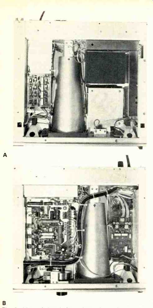
Fig. 3-View of chassis from above (A) and below (B).
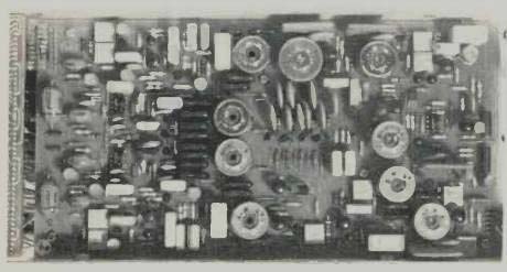
Fig. 4-Part of the i.f system.
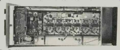
Fig. 5-Limiter section.
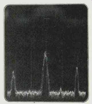
Fig. 6-Actual panoramic display. Note weak adjacent channel signal to the
right of tuned-to-center signal, also alternate channel signals on each
side of center.
Laboratory Measurements
Our usual FM performance measurements were made on the Sequerra Model 1 tuner. Figure 7 attempts to depict, graphically, some of the results, but each curve must be qualified by an excuse. To begin with, IHF sensitivity measured exactly 1.7 microvolts--about as low as IHF sensitivity can ever be if proper bandwidth is maintained, as it is in this model. So, IHF sensitivity is indeed "less than 2.0 µV" as claimed. The 50 dB quieting point was reached with a signal input of 1.9 µV. We usually quote THD for this condition, since in most tuners it still predominates over noise. In the case of the Model 1, however, the residual output at 50 dB quieting, as observed on an oscilloscope was very predominantly noise. Therefore, using an ordinary distortion analyzer (which can't tell the difference between noise and distortion), you'd come up with a figure of 0.3% "noise plus distortion" at 1.9 µV. Actual harmonic distortion is not separately visible on the 'scope until the noise dips below 63 dB or so, which is equivalent to about 0.07% residual THD.
However, even this figure needs qualifying. We are convinced that the Sound Technology FM Generator was not capable of supplying a test signal with better than 0.07% inherent modulation non-linearity, and therefore our reading of 0.07% THD is strictly the result of the test equipment. In other words, Sequerra knows that the THD of the Model 1 is lower than 0.07%, but can't really prove how much lower. His best guess is about 0.04%. The same applies to ultimate S/N, which measured about 75 dB. We know, however, that the generator is only guaranteed to suppress residual modulation down to ±25 Hz when used in the CW (unmodulated) mode. This would permit readings of over 70 dB, and the generator we used did permit a reading to 75 dB. There is no way of knowing how much further down the noise of the Model 1 really is--but we do know that it's lower than -75 dB. As for stereo, residual modulation of the generator is a bit worse so we come up with a -72 dB reading-in itself the lowest reading we have ever obtained, by far, for any tuner operating in the stereo mode, but probably a good deal higher than the true figures, which are just not obtainable with present day test equipment.
Figure 8 shows stereo separation versus frequency and THD versus frequency. The separation curves, at least, are definitive and meaningful and, as can be seen, show separation in excess of 60 dB at mid-band audio frequencies. At 15 kHz, separation was still in excess of 40 dB and well over 50 dB at the low end of the audio spectrum. The only thing the THD curves show is that there is some noticeable increase in THD at the extreme high frequencies in the stereo mode-noticeable, that is, if you consider a change of THD from 0.15% to 0.25% significant at frequencies above 6 kHz. What is obvious from these curves however, is the fact that there were NO visible or audible "beats" produced at any frequency as a result of any interaction between the 38 kHz products and audio products.
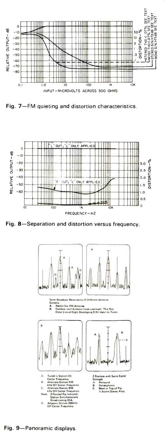
Fig. 7--FM quieting and distortion characteristics.
Fig. 8--Separation and distortion versus frequency.
Fig. 9--Panoramic displays.
Additional separate measurements were made for the specifications not listed by Sequerra, and it became obvious why he didn't bother with them. Here are some, with appropriate (and repetitious) comments. Alternate channel selectivity was in excess of 100 dB (we can't say how much in excess because of test equipment limitations). Image rejection was too high to be measured by our equipment. Spurious response rejection was in excess of 100 dB (we can't say how much in excess ... etc.). Capture ratio, as nearly as we could measure it (and it gets pretty tricky below 1 dB) was about 0.75 dB. As Dick Sequerra pointed out, however, a more meaningful statement could be made by pointing out that at 4 dB difference in signal strengths, the stronger signal "knocks out" the undesired weaker one to the extent of over 50 dB! Frequency response is something we can tell you about. It is accurate to the prescribed de-emphasis curve within ±0.2 dB from 30 Hz to 15 kHz. Rejection of 19 kHz output products and 38 kHz output products was in excess of 70 and 75 dB and therefore these components would be totally insignificant in terms of any recorder, regardless of its bias frequency. Rejection of SCA (67 kHz) was too great to be measured meaningfully.
After several hours of making these sometimes frustrating measurements, we decided to relax and play with the unit.
Listening and Utilization Tests
In case you have ever questioned the need for the kind of performance which the Sequerra Tuner can deliver-if you've doubted whether there is an audible difference-let me put those doubts to rest. You can (and I did) hear the difference. I don't think it's a simple case of lower distortion. I don't believe it's just better stereo separation. It's much more subtle than that, and 1 don't intend to explore the reasons in this lengthy report.
Suffice it to say that even in the face of admittedly poor station and transmitter practice (which has become rampant in FM over the last few years) we were able to find program sources that sounded better than we have ever heard FM reception before. Cleaner, quieter, more stable and more like what we had always believed FM radio was all about. Both in its measurements and in its actual audible performance, the Sequerra Model 1 is at least a whole order of magnitude better than anything else around.
Naturally, we were fascinated with the panoramic and other 'scope displays. But, as we used the panoramic display for a while, we came to realize how much we could learn from it. We were able to accurately measure signal strengths by noting the vertical height of the signal pips. (see Fig. 6.) We could even spot SCA transmissions from those stations that engage in this extra service. In one case, we noted extreme overmodulation of the SCA sub-carriers, something we had suspected regarding this particular station for years. What a great field strength meter this would have made in our previous studies of FM antenna capabilities some years back!
Fig. 10-Tuning displays.
Fig. 11-Tuning displays.
Fig. 12-Tuner vector for stereo display.
In the "Tuning Display" mode, we were able to perfectly center-tune any desired station, gauge station modulation levels (and, in many cases, overmodulation levels as well) and detect even the barest traces of multi-path interference. In this mode, too, signal strength is indicated by the vertical position of the display and calibration of the graticule marks was just about perfect. The display, incidentally, has automatic brightness circuitry built in. When the display collapses to a dot (as it will with no modulation in the "tuning" mode, or in the absence of audio signals in the "vector" mode), brightness is automatically reduced so that only a very dim spot of light appears, so as to protect the 'scope face from premature "burn spots." The kinds of displays we observed are illustrated in Fig. 9 (for the panoramic function), Figs. 10 and 11 (when using the display in the tuning mode), Fig. 12 (when using the display to check stereo separation and musical locations) and Fig. 13 (when using the display to feed separate, external audio signals via the rear input jacks). Our immediate thought after playing with these versatile functions for a while was that the FCC ought to equip every one of its mobile monitoring units with a Sequerra Model 1 unit. Perhaps then they could do some policing of the abuses in broadcasting practices which are prevalent all over the country. It wouldn't be a bad idea if every FM station in the country was equipped with this tuner too. It is sure to find its way into these places, because it can provide more useful information regarding a station's radiated signal than any other single piece of FM equipment (and that includes so-called "monitor" receivers) we have ever seen.
In the last analysis, a good FM tuner is for listening. And, ultimately, it is with the dedicated FM listener who demands perfection that the Sequerra Model 1 is sure to make its mark for years to come. As one who has been involved, professionally, with FM equipment for over two decades, I can remember only two tuners which became the classics of their time. The first was the famous REL tuner which was head and shoulders above everything else in the 1950s. In the 1960s, we were introduced to the Marantz 10-B (designed, by the way, by Dick Sequerra and his present active associate Sid Smith-both of whom are as dedicated to good sound as they were when I first met them years ago). And now, in the mid-70's, we have a new standard of excellence-The Sequerra Model 1. I have purposely avoided mentioning prices up to this point because I felt that it was important to understand that this product is in a class by itself and that price is secondary. When you come right down to it, for the features it has, for the performance it gives, and for the musical pleasure it can provide to anyone demanding the finest there is in an FM tuner, $2500.00 is not really all that much to pay for the Model 1. If you're really strapped for cash, but want the tuner so badly that you're willing to buy it without the panoramic analyzer feature (a mistake, in my opinion), you will be able to walk away with one for an even $2000.00-after Sequerra has filled his initial orders which all call for the panoramic version.
Fig. 13--External vector displaying external 4-channel audio program source.
One final word for any of you who may have seen a prototype of this unit at various exhibitions and shows. The unit is actually in production. I saw dozens of completed and partially completed models with my own eyes. The waiting period is at an end. There really is a Sequerra Model 1 Tuner available for purchase. Final confirmation of this fact was brought home to me at the end of my visit, when Dick Sequerra began discussing his thoughts on the next product (in the audio field) that he and Sid Smith are beginning to work on. (I'm not at liberty to discuss it!) I know these dedicated engineers well enough to state, categorically, that they would not even be thinking about the next design program unless they felt that their first magnificent product was safely on its way!
-Leonard Feldman
(Audio magazine, Aug. 1974)
Also see:
Sherwood S-6010CP Tuner (Apr. 1983)
Sherwood Model Micro/CPU 100 Stereo FM Tuner (Equip. Profile, Nov. 1977)
= = = =