By RICHARD J. KAUFMAN
Audio electronics are nearer to perfection than the mechanical parts, so it's logical to attempt enhancement of overall system performance by electronic means. One such method is bi-amplification.
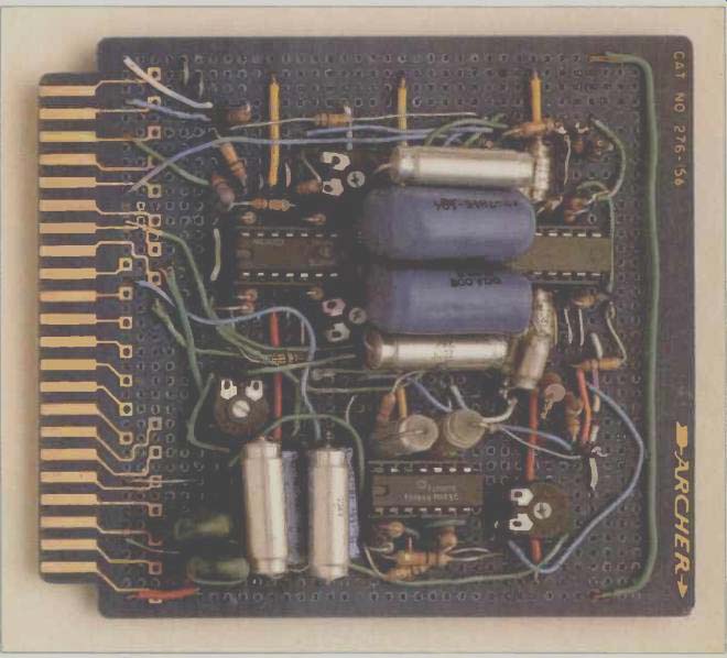
-------- Printed circuit card, used in the author's crossover, has
components mounted on a pre-etched breadboard.
Bi-amplification is an electronic technique that significantly improves the quality of sound from a system by the use of one or more extra amplifiers. In a conventional system, a single amplifier delivers power for a speaker system, as in Fig. 1A. The signal is then split by a passive crossover network of capacitors and inductors to feed separate drivers that are specialized to handle different portions of the audio spectrum. Biamplification splits the signal with an active crossover before power amplification, and separate amps are used for the different drivers in the speaker, as in Fig. 1B. Like the stereophonic recording and the linear tracking tonearm, biamplification is surprisingly ancient by the standard of audio history. It may have been used first by Hollywood sound men in the '30s. In the '50s, biamplification was the vogue in high-end audio, but the arrival of stereo made more dramatic use of a second amplifier, and biamplification disappeared from the consumer marketplace. Now it is being revived, mainly for sub woofer applications.
Biamping offers a number of very real advantages that have contributed to its commercial rebirth. Among these are a greater effective power handling capability, and hence a wider dynamic range, which is significant for reproducing digital recordings. To give an oversimplified example, a woofer capable of handling 100 watts and a tweeter capable of handling 25 watts, when combined in a conventional system, can safely handle 100 watts at most. When biamplified, the system can sound as loud as if it were handling 125 watts. A speaker system that can handle 75 watts, combined with a subwoofer capable of 150 watts, can sound like 225 watts.
Passive crossovers have problems that don't exist with active crossovers. A speaker's impedance is not constant with frequency. The impedances of capacitors and inductors also vary with frequency, and with temperature, voltage, age, humidity and from one production run to another. These problems are nonexistent or much less severe in the values needed for active circuits. The proper design of a passive crossover is difficult at best.
Subjectively, the listener's approval of biamping goes beyond what one might expect from specifications alone. Distortion is measurably lowered, but there seems to be a qualitative improvement as well. The amps have to deliver less power for a given loudness, and distortion tends to be lower at lower power levels-for amps and speakers alike. Clipping is masked in the bass, where it's most likely to occur, since the woofer won't reproduce clipping transients and the tweeter continues putting out undistorted sound. Isolating the tweeter from clipping transients in the bass channel protects it from burnout.
Using biamplification to feed a sub woofer at frequencies below 100 to 200 Hz offers some special advantages. Doppler distortion (sometimes called frequency modulation distortion) has been shown by P. A. Fryer to be inaudible when cone excursion is less than 4 mm. Such extreme excursions only occur at the lowest frequencies, and therefore isolating these frequencies eliminates Doppler distortion and reduces other forms of intermodulation distortion.
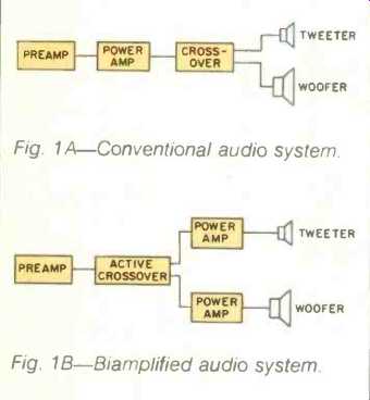
Fig. 1 A-Conventional audio system.
Fig. 1 B-Biamplified audio system.
Below 300 Hz, many authorities feel that pure tones are not perceived as directional. Using a crossover frequency much lower than this will filter out all traces of tones that are directional from the bass channel. This makes it possible to combine channels and use only one driver for the bass, saving space and the expense of extra equipment. Some people prefer two subwoofers, which allows 3 dB more loudness. While this approach simplifies speaker placement for phasing and stereo imaging, finding two locations that don't set off undesirable room resonances may be difficult. Both methods can give good results, both can have problems. In my opinion, there is no innate superiority to either approach.
The subwoofer format allows one to use bookshelf or mini-speakers as satellites. The smaller size and lesser number of drivers in such systems, as well as the simpler crossover networks, allow better dispersion and a more linear phase response in the midrange and high frequencies. This means better imaging and transient response. On the negative side, the large size of a typical subwoofer can be awkward, and so can finding an optimum place to put it. As a compensation, the satellite speakers can be smaller, and only one subwoofer may be used, so it is possible to use less total floor space. Some subwoofers are surprisingly compact, but the laws of physics dictate that any efficient subwoofer must be large, and thus also judged as a piece of furniture.
There are obstacles to biamplification. One must have a separate preamp, or preamp outputs on an integrated amp or receiver. An extra amp is needed, and so is an active crossover. These latter devices are still considered somewhat exotic; the sidebar describes their inner workings sufficiently so that the more technically minded can design their own, and it also details a specific design that can be built by a skilled amateur.
Choosing a Crossover Frequency
There are two major factors to consider in choosing a crossover frequency: Subwoofer placement and the resonance frequency of the satellite speakers. If the crossover frequency is too high, one will hear the subwoofer as a separate sound source, since attenuation of the directional, higher frequencies will not be great enough to completely eliminate them from the subwoofer. (If one is using two sub woofers, they should be placed with the main speakers.) For a second-order, 12-dB-per-octave roll-off, 80 Hz is the highest frequency that will give totally non-directional bass. With a third order, 18-dB-per-octave response, any frequency below 120 Hz should be satisfactory. If the subwoofer is placed between the satellites and at about the same distance from the favored listening area, higher crossover frequencies may be used. I prefer such placement, for it gives better phase and frequency response characteristics. Some commercial designs use a second-order crossover as high as 180 Hz, though here I would recommend an 18-dB-per-octave slope for a single subwoofer, unless a slight loss of stereo separation is tolerable.
The satellite speakers produce a significant amount of sound below the crossover frequency. It is especially important for their resonant frequency to be low enough to ensure that phase shift and response peaks that occur near this frequency do not impact the overall system response. As a rule of thumb, an acoustic suspension speaker's-3 dB response point should be at least an octave below the filter crossover frequency. Bass reflex speakers require a slightly greater margin, as much as 1 1/2 octaves, to avoid phase shift. A satellite that can be crossed in at 80 Hz must already have excellent bass response. Mini speakers demand a crossover of at least 160 Hz, and most bookshelf speakers will be satisfactory at about 110. (It is possible to break or bend these rules and get good results, depending on such variables as room acoustics, taste and luck, but more consistent results will be achieved by following these guidelines.) An advantage to a higher crossover point is that it relieves the satellite speakers of more power handling responsibility.
It is necessary to adjust the gain of the subwoofer to match that of the satellites, and most commercial active crossovers provide for this. Phasing is important, too. Some amps invert the signal, others do not; check Audio's Annual Equipment Directory to find out which do. Switching speaker leads is the easiest way to correct a mis phased signal.
Once the biamped system is set up, there is greater sonic detail, cleaner sound, and better imaging, both side to side and front to back, than with a passive crossover. If a subwoofer is used for the first time, some unusual problems may occur. Auxiliary feet for the turntable may be required to help damp unwanted vibrations if its built-in feet are not adequate when very low frequency signals are reproduced.
The first time I hooked up a subwoofer I discovered that my turntable was positioned at a standing wave maximum.
Whenever a piano recording contained a loud, low B, the howl of feedback was horrendous. The use of good damping feet, and moving the subwoofer out from the wall, cured the problem. In general, keep subwoofers out of corners and perhaps a foot or two away from any walls to avoid setting off room resonances of this sort.
Experiments will determine what suits a particular listening environment. Even if you are not manually inclined, the information presented here should enable you to make an intelligent choice among the active crossovers on the market.
Suggested Reading
C., Martin, High Performance Loudspeakers, Pentech Press Estover Road, Plymouth, Devon PL6 7PZ, England (1978)
Includes an extensive survey, with examples, of active and passive crossover techniques, plus all other known aspects of speaker design.
Jung, Walter G., IC Op-Amp Cookbook, Howard Sams, Indianapolis, Ind. 46268 (1974). If it can be done with op-amps, this book tells how.
Lancaster, Don, Active Filter Cookbook, Howard Sams (1975). The best guide to active filter design for the amateur.
==========
Crossovers--An Active Approach Filters
Any crossover network consists of filters. For loudspeakers, two basic types are used: High pass and low pass. As the names imply, a highpass filter passes high frequencies and blocks low frequencies, and vice versa. A fitter's cutoff frequency is the point where response is down by 3 dB and is sometimes called the half power point. A typical speaker system will have a low-pass filter for the woofer and a high-pass filter for the tweeter. In a three-way system the midrange driver will have a low-pass and a high-pass filter, resulting in a broad bandpass response.
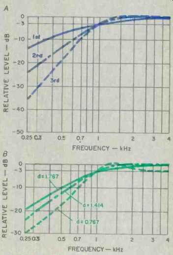
Fig. 2--Filter-response curves. First-, second-, and third-order high-pass
Butterworth responses (A) and second-order high-pass responses with different
damping factors (B).
This is simple enough, but there are different orders of filters. The term "order" refers to the order of the equation that describes the filter's response as a function of frequency, i.e., the largest exponent in the equation. The higher the order, the greater the filter's ultimate rate of attenuation and the greater the phase shift at the filter's cutoff point. The simplest filters are first order, consisting of either a single capacitor or inductor (coil). The ultimate rate of attenuation is 6 dB per octave. Second-order filters (a capacitor and an inductor) roll off at 12 dB per octave, third (three elements) at 18, fourth at 24, etc.
First- and second-order networks are the most common in speakers, though occasionally third and fourth order are used. Figure 2 shows several filter responses.
Another factor that affects filter response for orders greater than one is Q, the ratio of reactance to resistance in the filter network. The Q factor determines the rate of attenuation near the cutoff frequency, the smoothness of response in the pass band, and the linearity of phase shift. (Q is specified here by its inverse, damping or d.) Butterworth filters (d = 1.414 for the second order) have the best all-round combination of characteristics for most network applications.
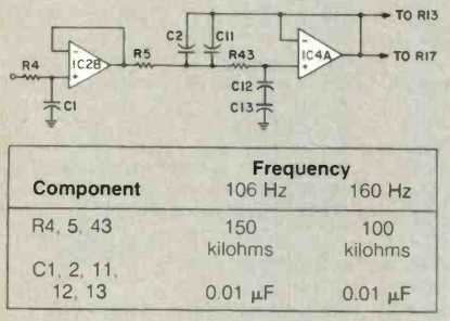
Fig. 3--Unity-gain Sallen & Key filters, where cutoff frequency
F = 1/[2 pi RC]
R is in ohms, and C is in Farads (1 µF = 0.000001 F).
Filters illustrated are second-order low pass (A), third-order low pass (B), second-order high pass (C), and third-order high pass (D).
Active Filter Circuits
Passive filters are made from capacitors and inductors. Active filters generally eliminate the inductors, using a device with gain, such as an FET or an op-amp, to supply the energy that would be stored in an inductor. One of the more popular circuits, due to its simplicity, is the unity-gain Sallen and Key filter. Design parameters for second- and third-order Butterworth responses are summarized in Fig. 3. Separate high- and low-pass filters of this type may be combined to make an active crossover network, but the responses are unlikely to be exact mirror images, due to component variation, and the required values, especially for capacitors, may be hard to locate. Note that for second-order networks, the high-pass and low-pass outputs are 180° out of phase, leading to signal cancellation. This is usually corrected by inverting the high-pass signal, though overall phase relationships become problematic.
A circuit that avoids some of these problems is the state-variable filter, illustrated in Fig. 4. It is actually an analog computer that "calculates" the desired response and provides simultaneous high- and low-pass outputs. The ratios of component values are easier to obtain, and it is less sensitive to component variation than a Sallen and Key filter. A disadvantage is that the circuit takes time to stabilize when power is applied or disconnected, sometimes resulting in transient 'thumps" which, must be circumvented.
Still another type of crossover, only recently available, uses a differential filter consisting of a single low-pass (or high-pass) filter. The complementary response is generated by subtracting the filter's output from the original signal. If a system's drivers are properly aligned, the theoretical result is an all-pass response with no phase shift and hence no degradation of transient response. One claim made for active differential crossovers is that they give a more uniform pressure response in a reflective listening environment, such as a home, than do conventional circuits. My own informal listening panel tests show differential crossovers to be preferred at 110 Hz. I have had no chance to test at higher frequencies, but judging from product reviews, a differential crossover will perform very well at higher crossover points.
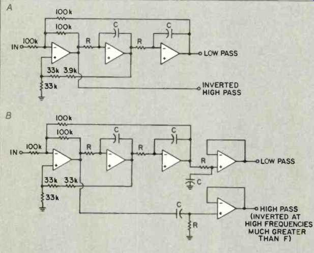
Fig. 4--State-variable filters, where
F = 1/[2 pi RC]
as in Fig. 3; circuits shown are second-order (A) and third-order (B).
The Circuit
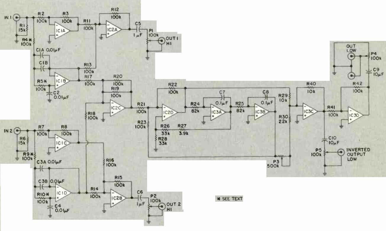
Fig. 5--Schematic of active crossover and subsonic filter. All resistors
are 1/4 watt, 5%; potentiometers are p.c. mounting, 1/4 watt; C9 and C10
are nonpolarized electrolytic, all other capacitors are-±10% plastic film
or better grade; ICs are Bi-FET devices, e.g. TL072CP or TL074CN.
Figure 5 is a schematic of the active crossover I am currently using. Circuit IC1A inverts the input signal, and R1 provides bias return for IC1B, which forms a second-order lowpass filter. The values shown for R4, R5 and C1A, C1B and C2 give a 112 Hz cutoff frequency. It can be lowered to 75 Hz by replacing R4 and R5 with 150-kilohm resistors. A third-order filter can be made by replacing IC1B and its associated components with the circuit in Fig. 6, which also gives component values for 160and 106-Hz crossovers.
Circuit IC2A is an inverting summing amplifier, and its output is the high-frequency differential response. Capacitor C5 blocks any d.c. offset from the output, and P1 allows output level adjustment. The second channel is similar. (To biamp a tweeter, it is better to use a high-pass filter for the primary response, since the sharper cutoff improves the tweeter's effective power handling ability.) It is possible to stop here and take low-pass signals from the outputs of IC1B and 1C1D, but if there is only one subwoofer it's necessary to combine the bass signals; IC2C averages them. Even with two subwoofers there are advantages to summing the bass channels this way.
Out-of-phase information will be cancelled, in-phase and single-channel information will be unaffected in loudness. Since these frequencies are non-directional, stereo separation is not affected. Out-of-phase information at low frequencies is noise: Rumble from the disc cutter and the turntable, resonance from the tonearm, and subsonic vibrations such as footsteps. Recordings are often blended in the studio to eliminate separation below 300 Hz, and natural miking has much the same blending effect.
The two channels are cut 180° to each other and re-phased by the cartridge. Out-of-phase signals at low frequencies would make the groove so narrow it would be too small to hold the stylus, and cause mistracking. Having the channels out of phase in the record groove results 'n the cancellation of vertical vibrations (such as rumble and footsteps) when the two channels are mixed. Perhaps for another medium, combining signals hasn't these advantages, but it will not result in the cancellation of any musical information. If one disagrees with this approach, omit R20 and connect R18 to a duplicate of the rest of the circuit, instead of to IC2C. If a mono amp is used to drive a single subwoofer, again omit R20 in order to sum the channels instead of averaging them.

Fig. 6A--Circuit schematic for third-order filter.
Fig. 6B--Table of component values for third-order filter.

Fig. 7--Schematic of power supply where T1 is 12 V, at least 250 mA, center
tapped; D1 is bridge rectifier, 50 V, 1 A; C1 P, C2P, C3P, and C4P are
1000 uF, 35 V electrolytic; C5P, C6P are 0.1 µF, 20% ceramic or plastic
film (mount a pair of these power supply decoupling capacitors on every
board); R1P, R2P are 68 ohms, 1/2 watt; R3P is 1 kilohm, 1/2 watt.
Any subwoofer worthy of the name needs a subsonic filter to limit unnecessary cone excursion, and this function is performed by ICs 2D, 3A, 3B and 3C. They are an elliptical filter. The high-pass output of a state-variable filter is summed with part of the low-pass output by IC3C. This results in a response null at a specific frequency, due to phase differences, and the null can be tuned by adjusting P3. At maximum resistance, the null frequency is 2.6 Hz; with P3 at minimum, the null is at 12.8 Hz. Above the null, attenuation is greater than for a second-order filter and is greater than a third-order filter at most settings. Below the null the response rises again, but, for a 10-Hz setting, is always down by more than 10 dB, which is the attenuation at d.c. With the 2.6-Hz setting, response at d.c. is down 20 dB; phase and transient response are about the same as for a simple second-order filter. I suggest setting P3 to maximum resistance and increasing the null frequency only if sub-sonics turn out to be a problem. (If P3 and R30 are omitted, the result is a plain second-order high-pass filter.)
The subsonic filter's cut-off frequency is set to 19 Hz by R24 and R25. Though 82 kilohms is a standard value, it is not widely stocked. Substituting two 39-kilohm resistors in series will raise the cutoff to 20 Hz; 100 kilohms will lower it to 16 Hz.
The output of IC3C is inverted, and IC3D flips it right side up again. Two outputs can be taken from the wiper of P4. Capacitor C9 is a 10-µF non-polarized electrolytic. Some audiophiles claim that bypassing such a Coupling capacitor with a polypropylene or silver mica capacitor will improve the sound, even for low-frequency applications. Capacitor 010 and P5 provide an inverted output if one is desired.
A pre-etched printed circuit breadboard (Radio Shack #276-153 or similar) was used to mount the components. Standard layout techniques are adequate for low-noise operation. Because of the large number of possible options, I have not supplied a parts list. Except for C9 and C10, which are nonpolarized electrolytic, all capacitors are plastic-film types. Polystyrene is superior but may not be readily available. Mylar is adequate and available from most electronics suppliers. The power supply is shown in Fig. 7. Capacitors C5P and C6P are the power supply de coupling capacitors, and a pair should be mounted on every printed circuit card used.
It is possible to assemble an active crossover entirely from parts bought at Radio Shack. Even including a fancy case, the project cost should be less than $40.
==========
(source: Audio magazine, Aug. 1982)
Also see:
New Lows on Home-Built Subwoofers (Aug. 1983)
Thunder in the Listening Room--Subwoofer Shootout (Nov. 1992)
Muffling the Neighbors: Ten Tips to Reduce Noise (Nov. 1990)
= = = =