Manufacturer's Specifications: Power Output: 205 watts per
channel, 20 Hz to 20 kHz, 8-ohm loads; 300 watts per channel, 4-ohm loads;
275 watts per channel, 2-ohm loads; 600 watts mono (bridged) mode, 8-ohm loads.
Total Harmonic Distortion: Less than 0.05%. SMPTEIM Distortion: Less than 0.05%.
TIM Distortion: Unmeasurable. Frequency Response: 20 Hz to 20 kHz, ±0.1 dB.
Slew Rate: Greater than 40 V/µS. Rise-Time: Less than 2.2 u.S. Dimensions:
4 7/8 in. (12.4 cm) H x 8 1/2 in. (21.6 cm) W x 12 in. (30.5 cm) D. Weight:
18 lbs. (8.2 kg). Price: $449.00. Company Address: 2200 South Ritchey, Santa
Ana, Cal. 92705.
Among the outstanding characteristics claimed for Soundcraftsmen's new PCR800 amplifier is the ability to deliver high power even when the speaker load impedance drops to zero ohms. The amplifier is equipped with a unique, thermo-coupled feedback system which utilizes multiple, precision temperature sensors throughout. When overheating takes place, an electronic sensing system accelerates the speed of the cooling fan, but, more importantly, if the fan alone cannot keep temperatures below safe limits, Soundcraftsmen's newly developed Phase Control Regulation (PCR) takes over and actually lowers the supply voltage being fed to the output transistors to reduce power dissipation, thereby reducing temperatures within the amplifier's output devices.
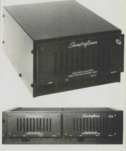
Considering its high power-output capability, the PCR800 is remarkably compact. The upper part of the front panel projects forward from the rest of the amplifier, and it is separated from the major assembly by a slab of foam which serves as an air filter for the ventilation fan. During normal operation, the fan revolves very quietly at a fairly slow speed. If the internal temperature increases substantially, the fan switches to its higher speed, at which point it becomes quite audible.
The only control on the front of the amplifier is an on/off rocker switch, augmented by a green "PCR" light which blinks while the amplifier is on. Faster-than-normal blinking tells the user either that the fan is in high-speed mode or that PCR action (about which more in a moment) is taking place to maintain continuous operation at optimum high-power output. Two red "Tru-clip" LEDS illuminate when the amplifier is clipping and, therefore, indicate that a distorted waveform is appearing at the output terminals.
The input jacks, at the rear of the amplifier, are the standard phono-tip type. Speaker terminals are color-coded and spaced for standard double-banana plugs. The left-and right-channel "hot" terminals are also spaced for a double-banana plug, to simplify bridging the amp to mono for greater power. Soundcraftsmen's series of "DX" preamplifiers can invert the phase of one channel's output, so no further inversion is necessary at one input of the amp when using it in bridged mode. If two amps are to be used in the bridged mode without such a preamplifier, an external bridging adaptor would be necessary.
Circuit Highlights
The circuitry of the PCR800 is rather conventional in its topology, employing the familiar differential-amplifier input stage, and bipolar amplifier and driver stages followed by four power MOS-FETs per channel as output devices.
The most innovative aspects of this design are in the power-supply system, a new approach to efficient amplifier design called Phase Control Regulation, or PCR. Soundcraftsmen's first model to employ the principle is this powerful PCR800 (205 watts per channel into 8 ohms, 300 watts into 4 ohms), a deceptively small power amp that weighs a mere 18 pounds.
As Soundcraftsmen explains it, the major thrust of legitimate engineering effort in amplifier design has focused on power-supply design improvements. After all, the power supply of an amplifier is the energy source that, indirectly, drives the loudspeakers. The most desirable characteristics of an "ideal" power supply would be huge power capacity, low output impedance, and good transient response. The power supply employed in the Phase Control Regulation amplifier has all of these attributes plus the added benefit of using substantially less expensive circuitry.
Essentially, PCR is a highly efficient means of controlling the average power supplied to an amplifier's output stages.
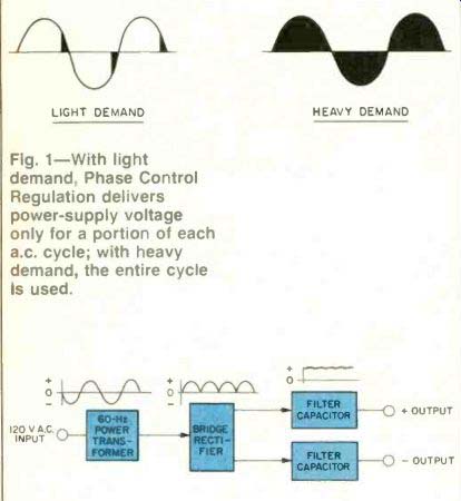
By rapid switching, it connects and disconnects an a.c. supply and its load for a precisely optimized fraction of each 60-Hz cycle of line voltage. When the amplifier is delivering a small amount of power (light load), only a small fraction of each a.c. cycle is used to provide power. When power demand is heavy, the power of the full a.c. cycle is delivered to the output stages. (See Fig. 1.)
To fully understand the operation of the PCR supply, a brief review of conventional, or linear, power-supply circuitry may be helpful. In this approach, illustrated in Fig. 2, the 120-V a.c. line voltage is supplied to a power transformer which provides line isolation and adjustment of the a.c. voltage level at its output. This voltage is full-wave rectified by a bridge rectifier consisting of ordinary diodes. The output of the diode bridge rectifier supplies pulsating positive and negative d.c. voltages, which are then filtered by large capacitors to provide the actual positive and negative voltages used to power the output transistors.
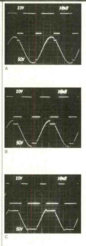
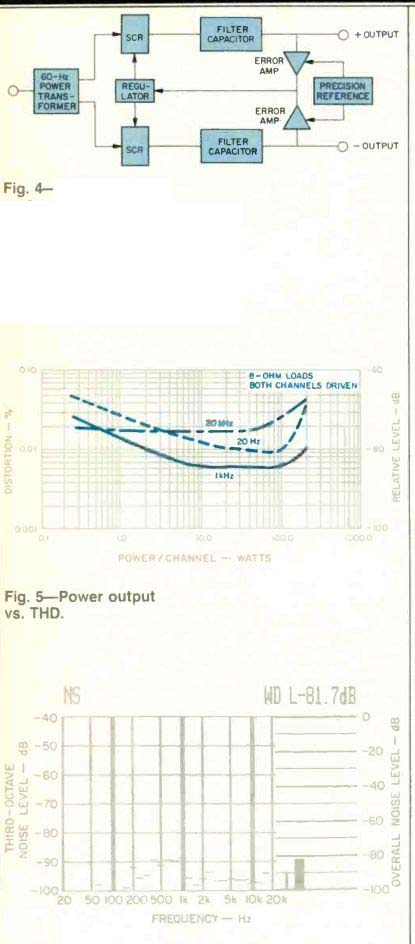
In the PCR800's power supply, the transformer output voltages are not applied to a diode bridge rectifier but to SCRs (silicon-controlled rectifiers). Unlike conventional diodes, SCRs have extra "gate" elements to which control voltages can be applied. By varying the control voltage's phase, an SCR can be regulated to conduct for varying portions of each a.c. cycle-any angle from 0° (non-conduction) to 180° (conduction over half the a.c. cycle, much like a conventional diode). The 'scope photo of Fig. 3A illustrates how the SCRs are turned on for only a small part of each a.c. alternation-the condition which would prevail when the amplifier load is small. In Fig. 3B, the amplifier load (power output) has increased to medium levels, and the SCRs' firing period (denoted by the flat "breaks" in the a.c. waveform) has increased somewhat. Finally, under conditions of heavy load (high power output), the SCRs conduct almost continuously, as would ordinary rectifiers (Fig. 3C). The SCRs' output, like that of ordinary rectifiers, is pulsating d.c. which must be smoothed by filter capacitors. Here, though, the filtered positive and negative supply voltages are constantly compared to a precision reference voltage, and an exact error-eliminating signal is applied to the Phase Control Regulator. This regulator controls the conduction time of the SCRs, maintaining the output voltage at a precise, fixed level (Fig. 4).
Phase Control Regulation can also perform other functions, such as increasing reliability through circuit protection and compensating for variations in line voltage. For example, thermal sensors positioned near the output transistors, as well as within the windings of the power transformer itself, will monitor temperature; if the temperature exceeds a predetermined level, that fact can be used to reduce the SCRs'. conduction time, lowering supply voltage to the output stages. Lowering the supply voltage in this manner reduces dissipation in the output devices, allowing them (or the power transformer, if it was overheating) to cool.
Because of the fixed voltage references built into the PCR system, power-line voltage variations can be monitored in much the same way, and the amplifier's supply voltage so regulated that virtually full power output can be delivered, even in a brownout. Conversely, if power-line voltage should rise to, say, 125 or even 130 V, the power-supply SCRs' angle of conduction would be reduced to maintain constant supply voltage to the output stages with no chance of exceeding their current or dissipation ratings.
Since the Phase Control Regulation circuitry is not in the audio signal path, it does not in any way degrade audio signal quality. Of course, if for any reason the SCRs have to lower the supply voltage, the maximum undistorted power output that the amplifier can then deliver will also be reduced-but that simply means earlier clipping or amplifier overload, with no danger to the amplifier itself or to any of its component parts. In fact, if a dead short is placed across this amplifier's speaker terminals-which can easily occur when an "invisible" strand of speaker cable bridges between the common and hot (+) output terminals-all that will happen is that the supply voltage will smoothly but rapidly drop from its ± 70 V down to ± 10 V or even lower.
Remove the short circuit, and the voltage rises up smoothly again, to its full value, as the SCRs resume conduction over a much greater angle of the a.c. input waveform, and normal operation is restored.
Most amplifiers are deliberately designed with poor power-supply regulation. As the load demands more power, their supply voltages drop or sag, making less voltage available. This type of design usually results in an amplifier's being able to provide very high power levels for very short peaks, but not when those peaks are repeated rapidly or high volume is sustained for a long period. The PCR approach results in a very tightly regulated power supply for the output stages. IHF dynamic headroom is going to be lower for this type of amplifier than for those employing "soft" or poorly regulated power supplies. But bear in mind that high dynamic headroom should not necessarily be regarded as a desirable attribute-it is simply the result of one design philosophy. Using a stiff power supply is another approach, as exemplified by PCR. Because of this design, the PCR800 has very low IHF dynamic headroom-no more than a fraction of 1 dB. On the other hand, it can provide more of its continuous rated power under the extreme line-voltage variations found in many real-world operating situations than would be the case with conventional soft power-supply amplifier designs.
Measurements
The Soundcraftsmen PCR800 delivered 211 watts per channel into 8-ohm loads at mid-frequencies and an almost equally high 205 watts per channel at the frequency extremes of 20 Hz and 20 kHz for its rated THD of 0.05%. At rated output, THD measured 0.01% at mid-frequencies, 0.038% at 20 Hz, and 0.04% at 20 kHz. Figure 5 is a plot of THD versus power output (per channel) for the key frequencies of 20 Hz, 1 kHz and 20 kHz. I also measured the amplifier's power output capability at lower impedance loads: With 4-ohm loads, the PCR800 delivered 305 watts per channel at mid-frequencies and more than 275 watts per channel over the entire audio frequency range for its rated THD of 0.05%. Even when 2-ohm loads were connected to this amplifier, it managed to deliver better than 230 watts per channel at mid-frequencies and just over 200 watts per channel over the entire audio frequency range.

Fig. 1--With light demand, Phase Control Regulation delivers power-supply
voltage only for a portion of each a.c. cycle; with heavy demand, the entire
cycle is used. Fig. 2--Conventional power supply.

Fig. 3--'Scope photos of voltage waveform appearing at power transformer secondary show how conduction angle of SCRs increases from light load (A) through medium (B) to heavy load (C).

Fig. 4--In the PCR system, a precision-referenced feedback signal regulates the output of silicon-controlled rectifiers, used in place of the ordinary diode rectifier in Fig. 2.

Fig. 6--Noise analysis referenced to 1-watt output, plus A-weighted noise measurement.
The SMPTE-IM distortion at rated output measured 0.023%, while CCIF (twin-tone) IM measured 0.005%. The IHF IM at rated power was lower than 0.03% (the limit of my test equipment's ability to read this specification). Frequency response was flat within 1.0 dB from 6 Hz to 100 kHz and within 3 dB from 3 Hz to 200 kHz. As I would have guessed, based upon this stiff power-supply design philosophy, IHF dynamic headroom was practically nil, measuring a mere 0.21 dB. Input sensitivity referenced to 1 watt measured exactly 100 mV, which corresponds to 1.4 V for rated power output (into 8-ohm loads). A-weighted signal-to-noise ratio with reference to 1 watt was 81.7 dB (as shown in the noise analysis plot of Fig. 6). Adding 23.1 dB to this measurement (the dB ratio between 1 watt and 205 watts) results in an S/N figure of 104.8 dB, essentially identical to the 105 dB claimed by the manufacturer. Damping factor was very high, with a reading of around 200, referred to 8 ohms, using a 50-Hz test signal. Slew factor was better than 5, while slew rate measured around 45 V/uS.
Use and Listening Tests
It's rather a pity that Soundcraftsmen's literature on the PCR800 says very little about how it sounds, because, besides packing a lot of stable power into a very small package, it delivers clean, accurate sound that is as good as any I have heard from an amplifier in this power class. I can't say for sure whether elimination of any and all current-limiting circuits within the signal path is responsible for the clarity and transparency of sound I heard when listening to some of my favorite CDs, but it certainly isn't doing any harm. Prompted by Soundcraftsmen's chief engineer, I bravely short-circuited the output terminals of one channel while playing full blast, all the while monitoring the B+ and B-supply voltages inside the amp. Of course, all semblance of musical sounds from the shorted channel ceased at once, and then, smoothly and with no apparent panic, the supply voltages dropped neatly down towards zero. There was no actual shutdown of the amplifier, nor did fuses blow or output transistors go up in smoke. When I freed the amp of its short, the voltage swiftly rose again (the SCRs having now been turned on to deliver a greater percentage of the power transformer's available a.c. voltage swings to the filter capacitors), and undistorted sound returned, none the worse for the experience! It's one thing to develop a good-sounding amplifier that remains accurate when no unusual demands are made on it and power-line voltage is exactly what it should be. It's another thing to achieve this in a powerful amplifier which is suited to the real world, where loudspeakers have dips in their impedance curves, utility companies provide out-of-tolerance line voltages, and users may subject their equipment to all sorts of thermal and short-circuit indignities. To have achieved this in an amplifier as compact as the PCR800 is truly remarkable; to sell that amplifier at $1.10 per watt (75 ohm if you use 4-ohm loads) is nothing short of miraculous!
-Leonard Feldman
(Audio magazine, Aug. 1984)
Also see:
Soundcraftsmen SP 4001 Preamplifier-Equalizer (Nov. 1980)
Soundcraftsmen Pro-Power Ten Amplifier (Sept. 1989)
Spectro-Acoustics Model 217 Preamplifier (Feb. 1978)
= = = =