By BASCOM H. KING
-----------
Rated Power Output: 220 watts into 8-, 4-, or 2-ohm load.
Dimensions: 18 in. W x 9 in. H x 22 in. D (46 cm x 23 cm x 56 cm).
Weight: 100 lbs. (45 kg) each.
Price: $8,995 per pair.
Company Address: 2790 Brighton Rd., Oakville, Ont., Canada L6H 5T4;
905/829-3838.
------------------
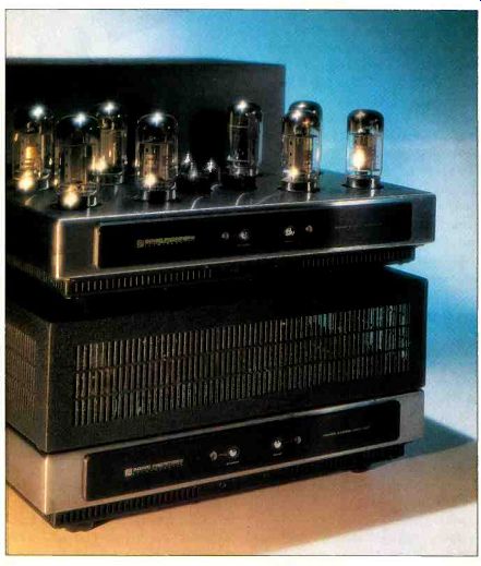
I have followed the rise of Sonic Frontiers as a major player in high-end audio for a number of years. I was impressed enough by its amps at the 1994 Winter Consumer Electronics Show to ask for a chance to review one. Though I had hoped to get the mono Power-3, the company's top-of-the line amplifier, I expected to get the Power-2 stereo amp. So I was surprised and delighted when a pair of 220-watt Power-3s arrived on my doorstep. (The UPS guy who delivered these 100-pound amps was not delighted.) Like most Sonic Frontiers components, the Power-3 is available with a black or gold front panel. The only features on that panel are pushbutton switches and indicator LEDs for "Standby" and "Power."

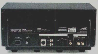
The power and output transformers and the filter capacitors are in a rectangular en closure at the back of the Power-3, which also forms the amp's rear panel. A switch near the input jacks on this panel selects balanced input, unbalanced (single-ended) noninverting input, or unbalanced inverting input. Balanced signals can be fed in through an XLR connector or a pair of RCA jacks. One of these RCA jacks also serves as the noninverting unbalanced input; the other serves as the inverting unbalanced in put. Another position on the input selector mutes the Power-3, shorts all of its inputs, and activates the bias-setting circuitry for the output tubes.
The Power-3's audio circuitry is in a stainless-steel chassis extending forward from the transformers' enclosure, and the tubes extend through the top of the chassis. Between the chassis and the transformer enclosure behind it is a small band, about 1 1/4 inches wide, that is slotted to help cool a number of heat sinks for power-supply components that are just below the band. A slotted metal cage fits over the tubes, giving the amplifier a simple box shape; the cage is attached to the chassis with captive screws. The amplifier's bottom plate is slotted to al low cool air to enter.
Inside the Power-3 are two p.c. boards. A large board beneath the chassis holds all the tube sockets and most of the audio circuit ry. This board is liberally drilled to allow air drawn up through the bottom plate to pass through to the tubes. A smaller board under the transformer enclosure holds power-supply components. Unlike many tube amps that have p.c. boards beneath their chassis, the Power-3 has most of its components mounted to the undersides of the boards for easy access.
All in all, the Power-3 is beautifully made and attractive. The chassis metalwork is first-rite, with Pemm nuts and machine screws fastening the pieces together. On the p.c. beards, high-quality components abound (e.g., capacitors from MIT, Solen, and Wima and resistors from Caddock and IRC). The insulation on the internal wiring appeared to be of Teflon.
I have seen most of the Power-3's basic circuit elements (see "Circuit Highlights") in various other amplifiers over the years. But Sonic Frontiers' combination of these elements, using modern components together with refinements wrought through countless hours of listening evaluation and circuit` tweaking, makes the Power-3 unique.
Measurements
The performance of the two Power-3s I received matched quite closely in most respects, so I'm presenting data for the one I've designated amp A, unless otherwise noted. As an example of how close the match was, voltage gain on the 8-ohm taps was 25.75 dB for amp A and 25.95 dB for amp B, whether I used their balanced or unbalanced inputs.
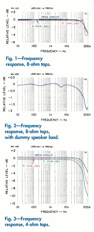
Frequency response, at the 8-ohm taps at a 2.83-volt output (1 watt into 8 ohm), is shown in Fig. 1. Across the audio band and beyond, the output varies very little with changes in load, an indication that the Power-3's output regulation is very good. Technically, where the curves first cross (at about 60 kHz), the output impedance be comes negative; when this happens, the out put increases for de creasing loads. The situation reverses at about 120 kHz, where the output impedance becomes positive again. This is a result of the compensation scheme the amplifier uses to ensure high-frequency stability; the output transformer is probably the major element involved. With a dummy load that mimics the impedance curve of a typical impedance-compensated two-way speaker, the Power-3's frequency response is still good (Fig. 2). The response variations caused by this load's impedance changes are small. (The vertical scale in Fig. 2 is magnified so that you can see them clearly.)

Fig. 1-Frequency response, 8-ohm taps.
Fig. 2-Frequency response, 8-ohm taps, with dummy speaker load.
Fig. 3-Frequency response, 4-ohm taps.
The Power-3's overall negative feedback is taken from its trans former's 8-ohm taps; frequency response should therefore be flattest at these taps, since coupling be tween this and the other taps is imperfect. Comparing Fig. 1 to a graph of response at the 4-ohm taps (Fig. 3) bears this out. At the 4-ohm taps, there is more high-frequency rolloff and less uniform output within the audio band when the loading is changed. Even so, the response with 2-ohm loading does not fall to-3 dB until it reaches about 90 kHz, an impressively wide bandwidth. I'd expect the rolloff and less uniform output regulation to be more pronounced on the 2-ohm taps, but I did not measure response there.
Square-wave response is presented in Fig. 4 for 8-ohm loading on the 8-ohm taps. Rise and fall times for a 10-kHz signal into 8 ohms (top trace) are 1.3 microseconds. With the 8-ohm load paralleled by a 2-microfarad capacitance (middle trace), ringing is not damped as quickly as it is in most other power amps. The excellent low-frequency response of the Ppwer-3 is revealed by the 40-Hz trace (bottom), which has almost no visible tilt.
The common-mode rejection ratios (CMRR) of the two amplifiers' balanced inputs differed somewhat. Amp A's CMRR was greater than 57 dB from 20 Hz to 20 kHz. Amp B's was greater than 73 dB from 20 Hz to 1 kHz, then started a gradual decrease that reduced it to 61 dB at 20 kHz.
The Power-3 generally has lower distortion in its balanced input mode because of better cancellation of even harmonics (Fig. 5). Plotting total harmonic distortion plus noise (THD + N), at 1 kHz and as a function of power for several loads (Fig. 6), reveals that performance is best when the load impedance ranges from the value that matches the selected output taps (e.g., 8 ohms on the 8-ohm taps) down to half that impedance (e.g., 4 ohms on the 8-ohm taps). For double the matched load (e.g., 16 ohms on the 8-ohm taps), the available power is reduced and there's some increase in distortion from about 2 watts up.
As with most amplifiers, the Power-3's THD + N increases at higher frequencies, although it does not really start rising until about 10 kHz. Figure 7 shows this for balanced input. (With an unbalanced input, THD + N was higher overall but its rise above 10 kHz was less noticeable.) A distortion spectrum analysis for a 1-kHz signal at an output of 10 watts revealed that the amplitude of the harmonics decreased rapidly as their order increased. The fifth harmonic reached a level of only 0.00005%, and higher harmonics were not detectable! The Power-3's distortion performance is among 0 the best I've seen in a tube power amplifier.
Output noise in the Power-3 was very low, especially in its balanced input mode. Measured via the un balanced noninverting input, out put noise for the less quiet of the two amps was 187 microvolts wideband, 155 microvolts from 22 Hz to 22 kHz, 36.7 microvolts from 400 Hz to 22 kHz, and 32.1 micro volts on an A-weighted basis. The IHF signal-to-noise ratio was 98.9 dB, an excellent figure.
The Power 3 had the highest damping factor I can recall measuring on a tube amp. On the 8-ohm taps, it was about 50 from 100 Hz to 2 kHz; it fell off gently on either side of this range, to about 32 at 10 Hz and 20 kHz. I did not measure damping factor on the 4-ohm taps directly, but the data I collected for Fig. 3 indicated a damping factor of about 30.
Dynamic power attainable--with the IHF tone-burst signal and an 8-ohm load on the 8-ohm taps--was 272 watts, and there was negligible output drop from power-supply sag over the course of the 20-millisecond burst. This 272-watt output corresponds to a dynamic headroom of 0.92 dB. Power at the visual onset of clipping was 250 watts, for a clipping headroom of 0.56 dB.
The Power-3's AC line draw was 1.4 amperes in standby and 4.1 amperes in idle. The AC line current stayed constant up to about 20 watts out. This is because the amplifier operates in what I call "rich" Class AB: It operates in Class A most of the time, with only loud passages crossing over into Class AB. At 8.2 amperes of line current for a pair of Power-3s, it definitely won't be cheap to run them all the time! However, the Power-3's front-panel "Standby" switch reduces power draw substantially. Sonic Frontiers recommends that the amps be in standby mode when not you're not listening to them. Since switching to standby and back does not affect the sound, I also recommend it.

Fig. 4-Square-wave response, 10 kHz into 8 ohms (top), 10 kHz into 8 ohms
in parallel with 2 pF (middle), and 40 Hz into 8 ohms (bottom).
Fig. 5-Distortion vs. power, 8-ohm load on 8-ohm taps.
Fig. 6-THD + N vs. power, 8-ohm taps.
Fig. 7-THD + N vs. frequency, 8-ohm load on 8-ohm taps.
Use and Listening Tests
Phono equipment in my system during the review period included an Oracle turntable fitted with a Well Tempered Ann and an Accuphase AC-2 moving-coil cartridge used with a Vendetta Research SCP 2C phono preamp. For CDs, a Sonic Frontiers SFT-1 or a Counterpoint DA-11A CD transport drove a Sonic Frontiers SFD-2 MkII D/A converter with a Genesis Digital Lens jitter-reduction device placed between the transport and the converter; digital cables were Illuminati DX50s. Other power amplifiers used for comparison were a Spectron 1KW, a Crown Macro Reference, and a pair of Quicksilver M135 tube amps.
The loudspeakers were Genesis Technologies Vs and B&W 801 Matrix Series 3s; the B&Ws were augmented from 20 to 50 Hz by a subwoofer in each channel.
I did most of my listening with the Sonic Frontiers Power-3s through the Genesis Vs. With these speakers, the Power-3s produced the best overall sound of all the amplifiers I had on hand, delivering absolutely amazing reproduction! There was a sense of ease, musical rightness, and spatial presence that continued to astound me, whether I was listening to my current reference CDs and LPs or to older recordings I hadn't heard in a while.
I had listened to other state-of-the-art tube amps with the Genesis V speakers at the Genesis Technologies factory, and the sound I got in my listening room with the Power-3s compared favorably to what I had heard there. Yet I must note that the Genesis Vs have their own servo bass amp, which handles frequencies below about 85 Hz.
Any power amp driving these speakers is therefore relieved of delivering the low bass.
As mentioned in "Circuit Highlights," the connections you use to select the Power-3's output taps are under the transformer. Thus, I had to turn each of these heavy amps over and change the connections whenever I switched between 4- and 8-ohm speakers. Since I started with the 4-ohm Genesis Vs, I listened to the 8-ohm B&Ws on the 4-ohm taps before I got around to resetting the amps to 8 ohms.
With the B&Ws, changing to the 8-ohm taps improved the overall presentation and gave the bass more punch.
The bass power and tightness of these amps were most impressive! Although the differences between the various amplifiers in my system weren't as obvious to me on the B&W 801s as on the Genesis Vs, the Power-3s sounded exceedingly good on these speakers, too. The words that came to mind as I listened included ease, dynamic nuance, lack of irritation, and musical believability. The Power-3s are among the very best amplifiers I have had the pleasure of auditioning.
I did find a few faults with the Power-3s, however. For example, when they were in standby mode, turning them completely off produced a strange noise through the speakers. This took the form of a chirp on the Genesis Vs and a grunt on the B&W 801s, but the two Power-3s each produced the same noises.
One amp also made an audible popping noise for a few minutes after I switched it from muting to an unbalanced input mode. The cages covering the front of the amps were rather resonant when struck; better mechanical damping would have prevented this. And then there's the matter of the 8.2 amperes of line current that it takes to run a pair of Power-3s-aah, but it's worth it to hear them.
CIRCUIT HIGHLIGHTS
The Power-3's circuitry is fully balanced, all the way from its input switching and muting section to its output transformer. Following its input connectors and input switch is a balanced input buffer stage. This is actually a pair of buffers, one for each signal phase. Each buffer is a cathode follower that uses the two halves of a 6922 dual-triode tube, with a constant-current tube source for each signal phase.
The outputs of the buffers are directly coupled to the voltage-amplifier stage, a cross-coupled phase inverter (i.e., a push pull stage with each phase of its input signal coupled to the cathode of one tube and the control grid of the opposite tube). Cross-coupling makes each input phase contribute equally to both output phases. (As a phase inverter for single-ended inputs, this circuit in the Power-3 should maintain its push-pull balance well, even when tubes age or if they're re placed.) Each plate output of this stage is coupled to the next stage through a two-resistor voltage divider. Each divider's series resistor is bypassed by a capacitor; its shunt resistor is taken to the-120-volt supply, which provides bias reference to the following stage.
That stage is the differential driver, a push-pull stage that boosts the voltage from the previous stage and provides the signal-voltage swing that will eventually drive the output tubes' grids. The output of this stage is capacitor-coupled to the next of the Power-3's circuit blocks, the output cathode follower.
This block, a push-pull circuit, is directly coupled to the output tubes' control grids. Two 5687 dual triodes are used here, each triode element handling the drive and bias adjustment for two of the output tubes.
The output stage uses eight Russian-made Svetlana 6550C beam power tubes in a push-pull parallel configuration. The tubes are connected for Ultra-Linear operation, with their screen grids connected to taps on the output transformer's primary winding.
The secondary winding of the output transformer is center-tapped and has separate pairs of output taps for 2-, 4-, and 8-ohm speakers. A barrier strip under the output transformer connects the single set of output binding posts to whichever pair of taps you wish to use.
Overall balanced negative feedback is taken from the 8-ohm taps of the output transformer's secondary back to the cross-coupled phase inverter stage. With in this loop is a balanced feedback loop from the cathode follower stage to the cross-coupled phase inverter stage. This provides some positive feedback, to in crease open-loop voltage gain. The inner feedback loop also has the effect of reducing overall distortion and output impedance. (Sonic Frontiers says it reduces the rise in distortion that occurs in many conventional designs above about 1 kHz.) Although positive feedback can be destabilizing, this loop's component values are carefully chosen to increase the Power-3's overall stability.
Regulated power supplies abound in the Power-3. Regulated supplies feed +100 and-120 volts to the input buffer stage. A +360-volt regulator supplies the plate circuit of the differential driver stage and is RC-decoupled for the plate supply to the cross-coupled phase inverter. An other regulator supplies +160 volts to the plates of the output cathode-follower stage. Each regulator circuit includes a bipolar constant-current source feeding zener regulator diodes; the outputs of these diodes drive N-channel MOS-FET source followers to supply the regulated output voltages. The high input impedance of the MOS-FETs' gates permit additional RC decoupling between these gates and the zener diodes without any loss of DC regulation; this should result in very low overall noise levels in the regulator outputs. Film bypass capacitors are used generously in all the regulator and power-supply circuits.
The output cathode-follower stage's negative supply is-310 volts; it is unregulated, to keep the output stage's plate cur rent more constant as the AC line voltage varies. The output stage's B+ supply is an unregulated +540 volts. Of interest is the use of International Rectifier HEXFRED (ultrafast, soft-recovery) rectifier diodes in this supply. Several noted designers have concluded that this type of rectifier makes circuits sound more realistic than they would with conventional slower rectifiers. The input buffer tubes' heaters are supplied by unregulated DC. The other tubes' heaters are AC powered.
B.H.K.
(Adapted from Audio magazine, Aug. 1996)
Also see:
Sonic Frontiers Processor 3 D/A Converter (July 1998)
Sonic Frontiers SFD-2 D/A Converter (Equip. Profile, Jan. 1995)
= = = =